2008 INFINITI QX56 brake
[x] Cancel search: brakePage 3569 of 4083

TM-22
< FUNCTION DIAGNOSIS >
A/T CONTROL SYSTEM
Input/Output Signal of TCM
INFOID:0000000001603992
*1: Spare for output speed sensor
*2: Spare for accelerator pedal position signal
*3: If these input and output signals are different, the TCM triggers the fail-safe function.
*4: CAN comm unications
Line Pressure ControlINFOID:0000000001603993
• When an input torque signal equivalent to the engine drive force is sent from the ECM to the TCM, the TCM
controls the line pressure solenoid.
Control item Line
pressure control Ve h i c l e
speed
control Shift
control Lock-up
control Engine
brake
control Fail-safe
function (*3) Self-diag-
nostics
function
Input Accelerator pedal position signal
(*4)XXXXXXX
Output speed sensor A/T X X X X X X
Output speed sensor MTR
(*1) (*4)XXXX X
Closed throttle position signal
(*4)(*2) X (*2) X X (*2) XX
Wide open throttle position signal
(*4)(*2) X (*2) X (*2) XX
Input speed sensor 1 X XXX X
Input speed sensor 2
(for 4th speed only) X
XXX X
Engine speed signals
(*4)XX
Transmission range switch XXXXXXX
A/T fluid temperature sensors 1, 2 X X X X X X X
ASCD Operation signal
(*4)XXXX
Overdrive cancel sig-
nal
(*4)XX X
TCM power supply voltage signal X X X X X X
Out-
put Direct clutch solenoid
X XX X
Input clutch solenoid X XX X
High and low reverse clutch sole-
noid XX
XX
Front brake solenoid X XX X
Low coast brake solenoid (ATF
pressure switch 2) XX
XXX
Line pressure solenoid XXXXXXX
TCC solenoid XX X
Starter relay XX
Revision: March 2010 2008 QX56
Page 3570 of 4083
A/T CONTROL SYSTEMTM-23
< FUNCTION DIAGNOSIS >
CEF
G H
I
J
K L
M A
B
TM
N
O P
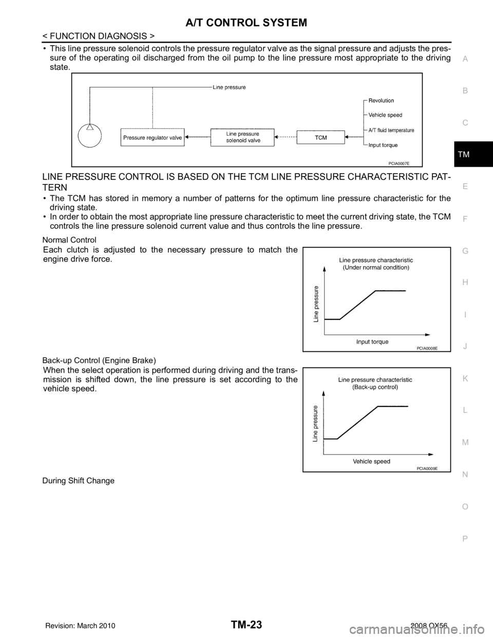
• This line pressure solenoid controls the pressure regulat or valve as the signal pressure and adjusts the pres-
sure of the operating oil discharged from the oil pump to the line pressure most appropriate to the driving
state.
LINE PRESSURE CONTROL IS BASED ON THE TCM LINE PRESSURE CHARACTERISTIC PAT-
TERN
• The TCM has stored in memory a number of patterns fo r the optimum line pressure characteristic for the
driving state.
• In order to obtain the most appropriate line pressure char acteristic to meet the current driving state, the TCM
controls the line pressure solenoid current value and thus controls the line pressure.
Normal Control
Each clutch is adjusted to the necessary pressure to match the
engine drive force.
Back-up Control (Engine Brake)
When the select operation is performed during driving and the trans-
mission is shifted down, the line pressure is set according to the
vehicle speed.
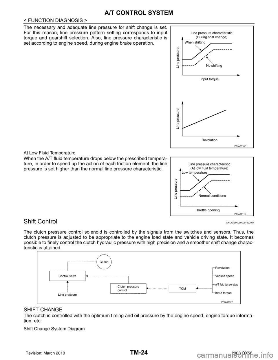
During Shift Change
PCIA0007E
PCIA0008E
PCIA0009E
Revision: March 2010 2008 QX56
Page 3571 of 4083
TM-24
< FUNCTION DIAGNOSIS >
A/T CONTROL SYSTEM
The necessary and adequate line pressure for shift change is set.
For this reason, line pressure pattern setting corresponds to input
torque and gearshift selection. Also, line pressure characteristic is
set according to engine speed, during engine brake operation.
At Low Fluid Temperature
When the A/T fluid temperature drops below the prescribed tempera-
ture, in order to speed up the action of each friction element, the line
pressure is set higher than the normal line pressure characteristic.
Shift ControlINFOID:0000000001603994
The clutch pressure control solenoid is controlled by the signals from the switches and sensors. Thus, the
clutch pressure is adjusted to be appropriate to the engine load state and vehicle driving state. It becomes
possible to finely control the clutch hydraulic pressure with high precision and a smoother shift change charac-
teristic is attained.
SHIFT CHANGE
The clutch is controlled with the optimum timing and oil pressure by the engine speed, engine torque informa-
tion, etc.
Shift Change System Diagram
PCIA0010E
PCIA0011E
PCIA0012E
Revision: March 2010 2008 QX56
Page 3573 of 4083
TM-26
< FUNCTION DIAGNOSIS >
A/T CONTROL SYSTEM
When shifting from the lock-up released state to the lock-up applied state, the current output to the torque con-
verter clutch solenoid is controlled with the TCM. In th is way, when shifting to the lock-up applied state, the
torque converter clutch is temporarily set to the half-clutched state to reduce the shock.
Half-clutched State
• The current output from the TCM to the torque converte r clutch solenoid is varied to gradually increase the
torque converter clutch solenoid pressure.
In this way, the lock-up apply pressure gradually rises and while the torque converter clutch piston is put into
half-clutched status, the torque converter clutch piston operating pressure is increased and the coupling is
completed smoothly.
Slip Lock-up Control
• In the slip region, the torque converter clutch solenoid current is controlled with the TCM to put it into the
half-clutched state. This absorbs the engine tor que fluctuation and lock-up operates from low speed.
This raises the fuel efficiency for 4GR and 5GR at both low speed and when the accelerator has a low
degree of opening.
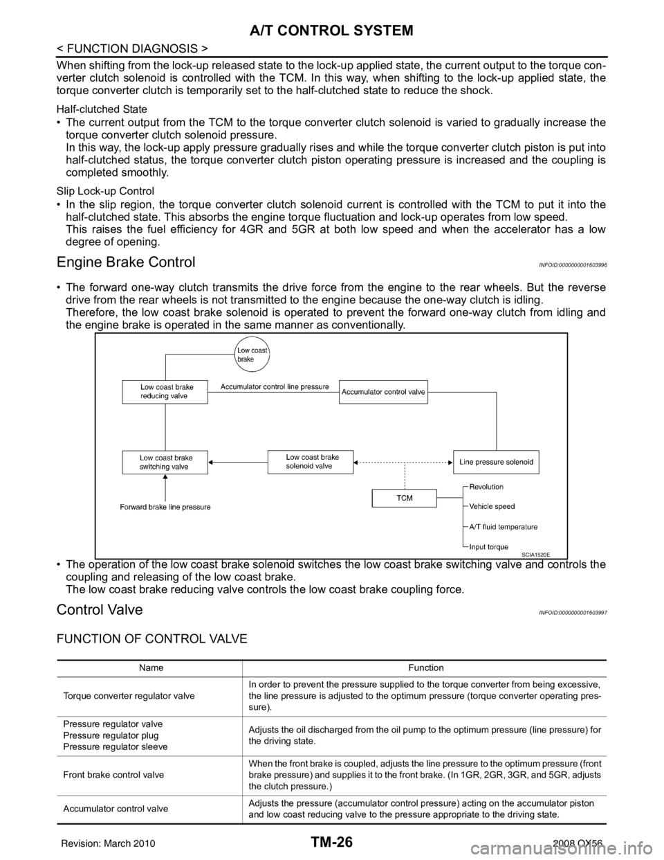
Engine Brake ControlINFOID:0000000001603996
• The forward one-way clutch transmits the drive force from the engine to the rear wheels. But the reverse drive from the rear wheels is not transmitted to the engine because the one-way clutch is idling.
Therefore, the low coast brake solenoid is operated to prevent the forward one-way clutch from idling and
the engine brake is operated in the same manner as conventionally.
• The operation of the low coast brake solenoid switches the low coast brake switching valve and controls the
coupling and releasing of the low coast brake.
The low coast brake reducing valve contro ls the low coast brake coupling force.
Control ValveINFOID:0000000001603997
FUNCTION OF CONTROL VALVE
SCIA1520E
Name Function
Torque converter regulator valve In order to prevent the pressure supplied to the torque converter from being excessive,
the line pressure is adjusted to the optimum pressure (torque converter operating pres-
sure).
Pressure regu lator valve
Pressure regulator plug
Pressure regu lator sleeve Adjusts the oil discharged from the oil pump to the optimum pressure (line pressure) for
the driving state.
Front brake control valve When the front brake is coupled, adjusts the line pressure to the optimum pressure (front
brake pressure) and supplies it to the front brake. (In 1GR, 2GR, 3GR, and 5GR, adjusts
the clutch pressure.)
Accumulator control valve Adjusts the pressure (accumulator control pressure) acting on the accumulator piston
and low coast reducing valve to the pressure appropriate to the driving state.
Revision: March 2010
2008 QX56
Page 3574 of 4083

A/T CONTROL SYSTEMTM-27
< FUNCTION DIAGNOSIS >
CEF
G H
I
J
K L
M A
B
TM
N
O P
FUNCTION OF PRESSURE SWITCH
Pilot valve A Adjusts the line pressure and produces the constant pressure (pilot pressure) required
for line pressure control, shift change control, and lock-up control.
Pilot valve B Adjusts the line pressure and produces the constant pressure (pilot pressure) required
for shift change control.
Low coast brake switching valve During engine braking, supplies the line pressure to the low coast brake reducing valve.
Low coast brake reducing valve When the low coast brake is coupled, adjusts the line pressure to the optimum pressure
(low coast brake pressure) and supplies it to the low coast brake.
N-R accumulator Produces the stabilizing pressure for when N-R is selected.
Direct clutch piston switching valve Operates in 4GR gear and switches the direct clutch coupling capacity.
High and low reverse clutch control valve When the high and low reverse clutch is coupled, adjusts the line pressure to the opti-
mum pressure (high and low reverse clutch pressure) and supplies it to the high and low
reverse clutch. (In 1GR, 3GR, 4GR and 5GR, adjusts the clutch pressure.)
Input clutch control valve When the input clutch is coupled, adjusts the line pressure to the optimum pressure (in-
put clutch pressure) and supplies it to the input clutch. (In 4GR and 5GR, adjusts the
clutch pressure.)
Direct clutch control valve When the direct clutch is coupled, adjusts the line pressure to the optimum pressure (di-
rect clutch pressure) and supplies it to the direct clutch. (In 2GR, 3GR, and 4GR, adjusts
the clutch pressure.)
TCC control valve
TCC control plug
TCC control sleeve Switches the lock-up to operating or released. Also, by performing the lock-up operation
transiently, lock-up smoothly.
Torque converter lubrication valve Operates during lock-up to switch the torque converter, cooling, and lubrication system
oil path.
Cool bypass valve Allows excess oil to bypass cooler circuit without being fed into it.
Line pressure relief valve Discharges excess oil from line pressure circuit.
N-D accumulator Produces the stabilizing pressure for when N-D is selected.
Manual valve Sends line pressure to each circuit according to the select position. The circuits to which
the line pressure is not sent drain.
Name
Function
Name Function
Pressure switch 2 (LC/B) Detects any malfunction in the low coast brake hydraulic pressure. When it detects any
malfunction, it puts the system into fail-safe mode.
Revision: March 2010
2008 QX56
Page 3576 of 4083
A/T SHIFT LOCK SYSTEMTM-29
< FUNCTION DIAGNOSIS >
CEF
G H
I
J
K L
M A
B
TM
N
O P
A/T SHIFT LOCK SYSTEM
System DescriptionINFOID:0000000001696150
• The selector lever cannot be shifted from “P” (Park) unless the brake pedal is applied and the ignition knob switch is turned to the “ON” position.
• The ignition knob switch cannot be returned to the “OFF” position unless the selector lever is placed in “P”
(Park).
• The shift lock mechanism is controlled by t he ON-OFF operation of the shift lock solenoid.
• The key switch and ignition knob switch lock mechanism is controlled by the ON-OFF operation of the key
lock solenoid.
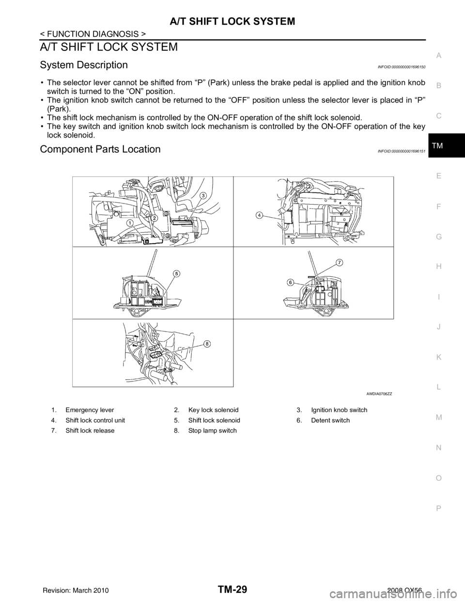
Component Parts LocationINFOID:0000000001696151
1. Emergency lever 2. Key lock solenoid3. Ignition knob switch
4. Shift lock control unit 5. Shift lock solenoid6. Detent switch
7. Shift lock release 8. Stop lamp switch
AWDIA0706ZZ
Revision: March 2010 2008 QX56
Page 3580 of 4083
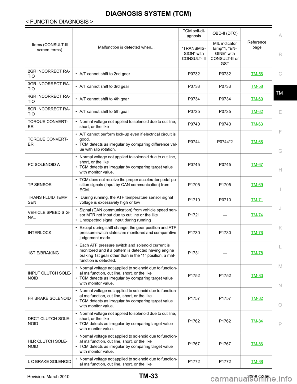
DIAGNOSIS SYSTEM (TCM)TM-33
< FUNCTION DIAGNOSIS >
CEF
G H
I
J
K L
M A
B
TM
N
O P
2GR INCORRECT RA-
TIO • A/T cannot shift to 2nd gear
P0732 P0732TM-56
3GR INCORRECT RA-
TIO• A/T cannot shift to 3rd gear
P0733 P0733TM-58
4GR INCORRECT RA-
TIO• A/T cannot shift to 4th gear
P0734 P0734TM-60
5GR INCORRECT RA-
TIO• A/T cannot shift to 5th gear
P0735 P0735TM-62
TORQUE CONVERT-
ER• Normal voltage not applied to solenoid due to cut line,
short, or the like P0740 P0740
TM-63
TORQUE CONVERT-
ER• A/T cannot perform lock-up even if electrical circuit is
good.
• TCM detects as irregular by comparing difference val- ue with slip rotation. P0744 P0744*2
TM-66
PC SOLENOID A• Normal voltage not applied to solenoid due to cut line,
short, or the like
• TCM detects as irregular by comparing target value with monitor value. P0745 P0745
TM-67
TP SENSOR• TCM does not receive the proper accelerator pedal po-
sition signals (input by CAN communication) from
ECM. P1705 P1705
TM-69
TRANS FLUID TEMP
SEN• During running, the ATF temperature sensor signal
voltage is excessively high or low P1710 P0710
TM-71
VEHICLE SPEED SIG-
NAL• Signal (CAN communication) from vehicle speed sen-
sor MTR not input due to cut line or the like
• Unexpected signal input during running P1721
—TM-74
INTERLOCK • Except during shift change, the gear position and ATF
pressure switch states are monitored and comparative
judgement made. P1730 P1730
TM-76
1ST E/BRAKING• Each ATF pressure switch and solenoid current is
monitored and if a pattern is detected having engine
braking 1st gear other than in the "1" position, a mal-
function is detected. P1731
—TM-78
INPUT CLUTCH SOLE-
NOID • Normal voltage not applied to solenoid due to function-
al malfunction, cut line, short, or the like
• TCM detects as irregular by comparing target value with monitor value. P1752 P1752
TM-80
FR BRAKE SOLENOID• Normal voltage not applied to solenoid due to function-
al malfunction, cut line, short, or the like
• TCM detects as irregular by comparing target value with monitor value. P1757 P1757
TM-82
DRCT CLUTCH SOLE-
NOID• Normal voltage not applied to solenoid due to cut line,
short, or the like
• TCM detects as irregular by comparing target value with monitor value. P1762 P1762
TM-84
HLR CLUTCH SOLE-
NOID• Normal voltage not applied to solenoid due to function-
al malfunction, cut line, short, or the like
• TCM detects as irregular by comparing target value with monitor value. P1767 P1767
TM-86
L C BRAKE SOLENOID• Normal voltage not applied to solenoid due to function-
al malfunction, cut line, short, or the like P1772 P1772
TM-88
Items (CONSULT-III
screen terms) Malfunction is detected when... TCM self-di-
agnosis OBD-II (DTC)
Reference page
“TRANSMIS-
SION” with
CONSULT-III MIL indicator
lamp*1, “EN-
GINE” with
CONSULT-III or
GST
Revision: March 2010 2008 QX56
Page 3581 of 4083

TM-34
< FUNCTION DIAGNOSIS >
DIAGNOSIS SYSTEM (TCM)
*1: Refer to EC-55, "Malfunction Indicator Lamp (MIL)".
*2:These malfunctions cannot be displayed MIL if another malfunction is assigned to MIL.
DATA MONITOR MODE
Display Items List
X: Standard, —: Not applicable
LC/B SOLENOID FNCT • TCM detects an improper voltage drop when it tries to
operate the solenoid valve.
• Condition of ATF pressure switch 2 is different from
monitor value, and relation between gear position and
actual gear ratio is irregular. P1774 P1774*2
TM-90
NO DTC IS DETECTED
FURTHER TESTING
MAY BE REQUIRED• No NG item has been detected.
XX
Items (CONSULT-III
screen terms) Malfunction is detected when... TCM self-di-
agnosis OBD-II (DTC)
Reference page
“TRANSMIS-
SION” with
CONSULT-III MIL indicator
lamp*1, “EN-
GINE” with
CONSULT-III or
GST
Monitored item (Unit) Monitor Item Selection
Remarks
ECU IN-
PUT SIG-
NALS MAIN SIG-
NALS SELEC-
TION
FROM
MENU
VHCL/S SE·A/T (km/h) XXX Output speed sensor
VHCL/S SE·MTR (km/h) X— X
ACCELE POSI (0.0/8) X— X Accelerator pedal position signal
THROTTLE POSI (0.0/8) XXXDegree of opening for accelerator recognized by
the TCM
For fail-safe operation, the specific value used
for control is displayed.
CLSD THL POS (ON-OFF display) X— X
Signal input with CAN communications
W/O THL POS (ON-OFF display) X— X
BRAKE SW (ON-OFF display) X— X Stop lamp switch
GEAR —XXGear position recognized by the TCM updated
after gear-shifting
ENGINE SPEED (rpm) XXX
INPUT SPEED (rpm) XXX
OUTPUT REV (rpm) XXX
GEAR RATIO —XX
TC SLIP SPEED (rpm) —XXDifference between engine speed and torque
converter input shaft speed
F SUN GR REV (rpm) —— X
F CARR GR REV (rpm) —— X
ATF TEMP SE 1 (V) X— X
ATF TEMP SE 2 (V) X— X
ATF TEMP 1 (° C) —XX
ATF TEMP 2 (° C) —XX
BATTERY VOLT (V) X— X
ATF PRES SW 1 (ON-OFF display) XXX Not mounted but displayed.
Revision: March 2010 2008 QX56