Page 2812 of 4083

PG
HARNESSPG-45
< COMPONENT DIAGNOSIS >
C
DE
F
G H
I
J
K L
B A
O P
N
C1 E5 W/24 : To F14
C1 E119 W/16: IPDM E/R (intelligent power distri-
bution module engine room)
C2 E7 GR/2 : Fusible link box (battery) D1 E120 W/6: IPDM E/R (intelligent power distri-
bution module engine room)
C2 E9 — : Body ground E1 E121 BR/12: IPDM E/R (intelligent power distri-
bution module engine room)
D4 E11 B/8 : Front combination lamp LH (without
daytime running lights) C1 E122 W/12: IPDM E/R (intelligent power distri-
bution module engine room)
D4 E11 B/8 : Front combination lamp LH (with
daytime running lights)
C1 E123 BR/8: IPDM E/R (intelligent power distri-
bution module engine room)
D3 E12 B/5 : Stop lamp relay D1 E124 W/6: IPDM E/R (intelligent power distri-
bution module engine room)
D4 E14 — : Body ground F3 E125 B/47: ABS actuator and electric unit
(control unit)
C2 E15 — : Body ground D4 E126 — : Body ground
C1 E16 B/40 : ECM C2 E130 W/2 : Compressor motor relay
E4 E18 GR/2 : Front wheel sensor LH C3 E131 W/2 : Compressor motor relay
D1 E19 W/16 : To F33 C3 E134 GR/6 : ICC brake hold relay
E3 E21 GR/2 : Brake fluid level switch C2 E135 GR/2 : Transfer dropping resister
E2 E23 GR/6 : Front wiper motor C1 E140 BR/6 : Trailer tow relay-2
D4 E24 — : Body ground B2 E153 W/2 : Transfer motor relay
F3 E25 BR/3 : Intelligent key warning buzzer B2 E154 W/2 : Transfer motor relay
C3 E27 BR/2 : Fusible link box (battery) D3 E156 L/4 : Trailer turn relay LH
C2 E30 /1 : Fusible link box (battery )D3 E157 L/4 : Trailer turn relay RH
E3 E31 B/3 : Front pressure sensor D5 E158 B/3 : Front sonar sensor LH outer
E3 E32 B/3 : Rear pressure sensor D5 E159 GR/3 : To E164
E1 E39 W/2 : To F34 B4 E160 GR/3 : To E165
D3 E40 B/3 : To E201 C3 E161 B/3 : Battery current sensor
D3 E41 SMJ : To C1 B4 E162 B/3 : Front sonar sensor LH inner
D3 E42 B/6 : ICC sensor C5 E163 B/3 : Front sonar sensor RH inner
E1 E46 B/5 : Transfer shift high relay D5 E164 GR/3 : To E159
D2 E47 B/5 : Transfer shift lo w relayA4 E165 GR/3 : To E160
C4 E48 B/3 : Refrigerant pressure sensor A3 E166 B/3 : Front sonar sensor RH outer
E3 E49 B/6 : Active booster Engine room sub-harness
D1 E69 L/4 : Transfer shut off relay D3 E201 B/3 : To E40
D5 E101 B/3 : Front turn-fog lamp LH C1 E202 /1 : Fusible link box (battery)
A4 E102 B/3 : Front turn-fog lamp RH C2 E203 — : Engine ground
C3 E103 B/5 : Daytime light relay C3 E204 /1 : Generator
D4 E105 BR/2 : Front and rear washer motor C3 E205 B/3 : Generator
E4 E106 BR/2 : Washer fluid level switch C3 E206 /1 : Generator
B3 E107 B/8 : Front combination lamp LH
C5 E113 W/2 : Cooling fan motor
Revision: March 2010 2008 QX56
Page 2814 of 4083
PG
HARNESSPG-47
< COMPONENT DIAGNOSIS >
C
DE
F
G H
I
J
K L
B A
O P
N
A3 E34 W/24 : To B40
A4 E35 W/12 : To B41
A4 E36 W/2 : To B42
B3 E37 BR/2 : ICC brake switch
B3 E38 W/4 : Stop lamp switch
B3 E109 GR/2 : Pedal adjusting motor
G4 E139 W/8 : To B107
F3 E142 W/24 : Transfer control unit
F3 E143 GR/24 : Transfer control unit
G3 E152 SMJ : To M31
Revision: March 2010
2008 QX56
Page 2973 of 4083

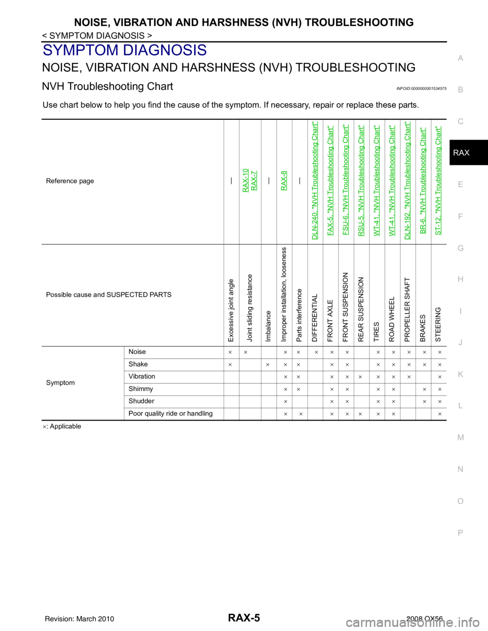
NOISE, VIBRATION AND HARSHNESS (NVH) TROUBLESHOOTINGRAX-5
< SYMPTOM DIAGNOSIS >
CEF
G H
I
J
K L
M A
B
RAX
N
O P
SYMPTOM DIAGNOSIS
NOISE, VIBRATION AND HARSHN ESS (NVH) TROUBLESHOOTING
NVH Troubleshooting ChartINFOID:0000000001534575
Use chart below to help you find the cause of the symptom. If necessary, repair or replace these parts.
×: Applicable
Reference page
—
RAX-10RAX-7—
RAX-8—
DLN-240, "
NVH Troubleshooting Chart
"
FAX-5, "
NVH Troubleshooting Chart
"
FSU-6, "
NVH Troubleshooting Chart
"
RSU-5, "
NVH Troubleshooting Chart
"
WT-41, "
NVH Troubleshooting Chart
"
WT-41, "
NVH Troubleshooting Chart
"
DLN-192, "
NVH Troubleshooting Chart
"
BR-6, "
NVH Troubleshooting Chart
"
ST-12, "
NVH Troubleshooting Chart
"
Possible cause and SUSPECTED PARTS
Excessive joint angle
Joint sliding resistance
Imbalance
Improper installation, looseness
Parts interference
DIFFERENTIAL
FRONT AXLE
FRONT SUSPENSION
REAR SUSPENSION
TIRES
ROAD WHEEL
PROPELLER SHAFT
BRAKES
STEERING
Symptom Noise
×× ×× ××× ×××××
Shake × × ×× ×× ×××××
Vibration ×× ××× ××× ×
Shimmy ×× ×× ×× ××
Shudder × ××××××
Poor quality ride or handling ×× ××× ×× ×
Revision: March 2010 2008 QX56
Page 2975 of 4083
REAR DRIVE SHAFTRAX-7
< ON-VEHICLE REPAIR >
CEF
G H
I
J
K L
M A
B
RAX
N
O P
ON-VEHICLE REPAIR
REAR DRIVE SHAFT
ComponentINFOID:0000000001534582
Rear Drive Shaft
WDIA0263E
1. Rear final drive assembly 2. Rear drive shaft3. Rear brake and hub assembly
4. Cotter pin
Revision: March 2010 2008 QX56
Page 2976 of 4083

RAX-8
< REMOVAL AND INSTALLATION >
WHEEL HUB
REMOVAL AND INSTALLATION
WHEEL HUB
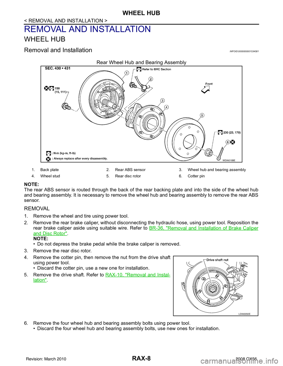
Removal and InstallationINFOID:0000000001534581
Rear Wheel Hub and Bearing Assembly
NOTE:
The rear ABS sensor is routed through the back of the rear backing plate and into the side of the wheel hub
and bearing assembly. It is necessary to remove the wheel hub and bearing assembly to remove the rear ABS
sensor.
REMOVAL
1. Remove the wheel and tire using power tool.
2. Remove the rear brake caliper, without disconnecting the hydraulic hose, using power tool. Reposition the
rear brake caliper aside using suitable wire. Refer to BR-36, "
Removal and Installation of Brake Caliper
and Disc Rotor".
NOTE:
• Do not depress the brake pedal while the brake caliper is removed.
3. Remove the rear disc rotor.
4. Remove the cotter pin, then remove the nut from the drive shaft using power tool.
• Discard the cotter pin, use a new one for installation.
5. Remove the drive shaft. Refer to RAX-10, "
Removal and Instal-
lation".
6. Remove the four wheel hub and bearing assembly bolts using power tool. • Discard the four wheel hub and bearing assembly bolts, use new ones for installation.
WDIA0189E
1. Back plate 2. Rear ABS sensor3. Wheel hub and be aring assembly
4. Wheel stud 5. Rear disc rotor6. Cotter pin
LDIA0050E
Revision: March 2010 2008 QX56
Page 2977 of 4083

WHEEL HUBRAX-9
< REMOVAL AND INSTALLATION >
CEF
G H
I
J
K L
M A
B
RAX
N
O P
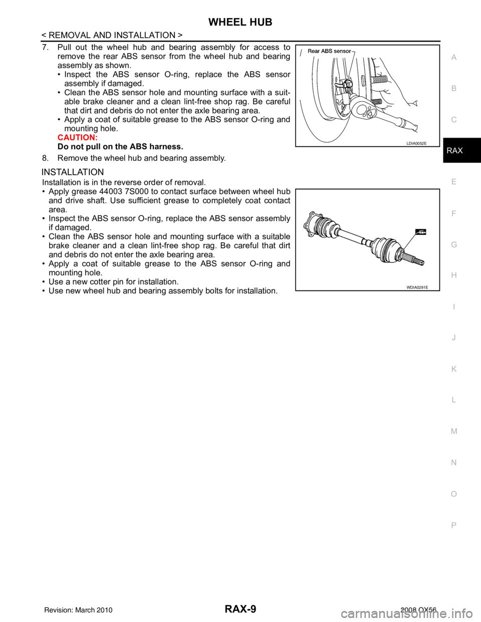
7. Pull out the wheel hub and bearing assembly for access to remove the rear ABS sensor from the wheel hub and bearing
assembly as shown.
• Inspect the ABS sensor O-ri ng, replace the ABS sensor
assembly if damaged.
• Clean the ABS sensor hole and mounting surface with a suit-
able brake cleaner and a clean lint-free shop rag. Be careful
that dirt and debris do not enter the axle bearing area.
• Apply a coat of suitable grease to the ABS sensor O-ring and
mounting hole.
CAUTION:
Do not pull on the ABS harness.
8. Remove the wheel hub and bearing assembly.
INSTALLATION
Installation is in the reverse order of removal.
• Apply grease 44003 7S000 to contact surface between wheel hub and drive shaft. Use sufficient grease to completely coat contact
area.
• Inspect the ABS sensor O-ring, replace the ABS sensor assembly
if damaged.
• Clean the ABS sensor hole and mounting surface with a suitable brake cleaner and a clean lint-free shop rag. Be careful that dirt
and debris do not enter the axle bearing area.
• Apply a coat of suitable grease to the ABS sensor O-ring and mounting hole.
• Use a new cotter pin for installation.
• Use new wheel hub and bearing assembly bolts for installation.
LDIA0052E
WDIA0291E
Revision: March 2010 2008 QX56
Page 3043 of 4083
RSU-4
< PREPARATION >
PREPARATION
PREPARATION
PREPARATION
Commercial Service ToolINFOID:0000000001534648
Tool nameDescription
Power tool • Removing wheel nuts
• Removing brake caliper assembly
• Removing rear suspension component
parts
PBIC0190E
Revision: March 2010 2008 QX56
Page 3044 of 4083

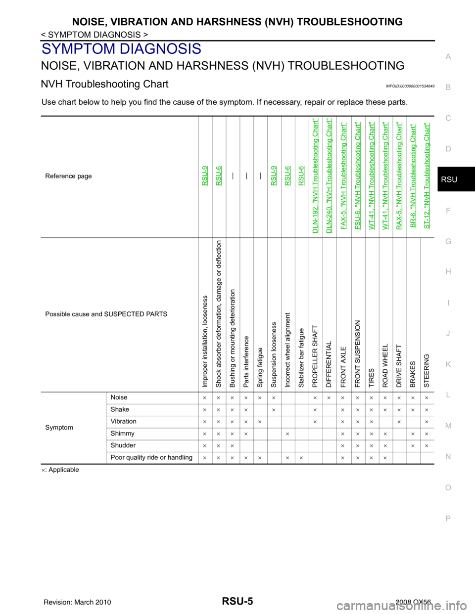
NOISE, VIBRATION AND HARSHNESS (NVH) TROUBLESHOOTINGRSU-5
< SYMPTOM DIAGNOSIS >
C
DF
G H
I
J
K L
M A
B
RSU
N
O P
SYMPTOM DIAGNOSIS
NOISE, VIBRATION AND HARSHN ESS (NVH) TROUBLESHOOTING
NVH Troubleshooting ChartINFOID:0000000001534649
Use chart below to help you find the cause of the symptom. If necessary, repair or replace these parts.
×: ApplicableReference page
RSU-9RSU-6—
—
—
RSU-9RSU-6RSU-6
DLN-192, "
NVH Troubleshooting Chart
"
DLN-240, "
NVH Troubleshooting Chart
"
FAX-5, "
NVH Troubleshooting Chart
"
FSU-6, "
NVH Troubleshooting Chart
"
WT-41, "
NVH Troubleshooting Chart
"
WT-41, "
NVH Troubleshooting Chart
"
RAX-5, "
NVH Troubleshooting Chart
"
BR-6, "
NVH Troubleshooting Chart
"
ST-12, "
NVH Troubleshooting Chart
"
Possible cause and SUSPECTED PARTS
Improper installation, looseness
Shock absorber deformation, damage or deflection
Bushing or mounting deterioration
Parts interference
Spring fatigue
Suspension looseness
Incorrect wheel alignment
Stabilizer bar fatigue
PROPELLER SHAFT
DIFFERENTIAL
FRONT AXLE
FRONT SUSPENSION
TIRES
ROAD WHEEL
DRIVE SHAFT
BRAKES
STEERING
Symptom Noise
×××××× ××× ××××××
Shake ×××× × × × ××××××
Vibration ××××× × × ×× × ×
Shimmy ×××× × × ××× ××
Shudder ××× × ××× ××
Poor quality ride or handling ××××× ×× × ×××
Revision: March 2010 2008 QX56