2008 INFINITI QX56 air condition
[x] Cancel search: air conditionPage 2163 of 4083
IDENTIFICATION INFORMATIONGI-21
< FEATURES OF NEW MODEL >
C
DE
F
G H
I
J
K L
M B
GI
N
O P
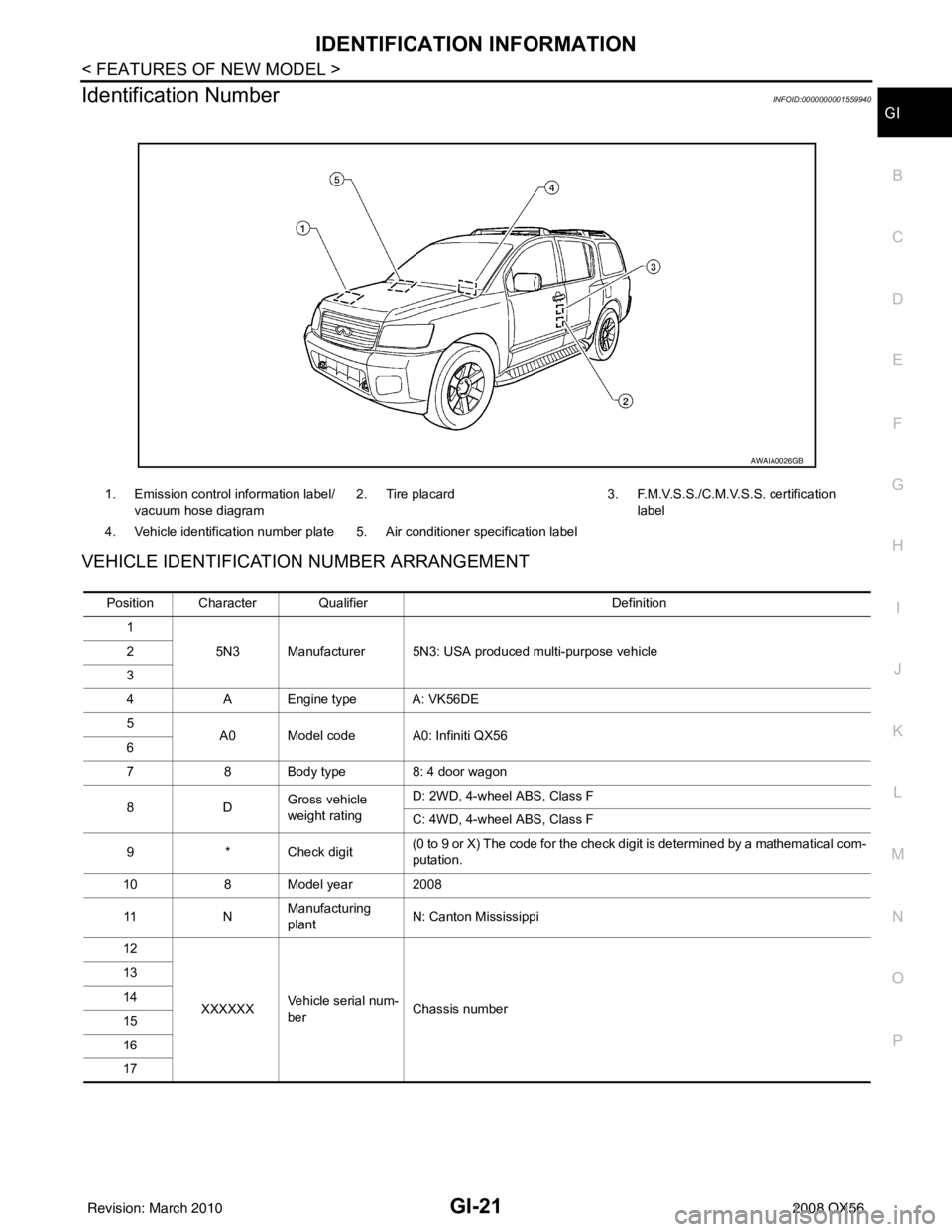
Identification NumberINFOID:0000000001559940
VEHICLE IDENTIFICATION NUMBER ARRANGEMENT
1. Emission control information label/ vacuum hose diagram 2. Tire placard 3. F.M.V.S.S./C.M.V.S.S. certification
label
4. Vehicle identification number plate 5. Air conditioner specification label
AWAIA0026GB
Position Character Qualifier Definition
1 5N3 Manufacturer 5N3: USA produced multi-purpose vehicle
2
3
4 A Engine type A: VK56DE
5 A0 Model code A0: Infiniti QX56
6
7 8 Body type 8: 4 door wagon
8D Gross vehicle
weight ratingD: 2WD, 4-wheel ABS, Class F
C: 4WD, 4-wheel ABS, Class F
9 * Check digit (0 to 9 or X) The code for the check digit is determined by a mathematical com-
putation.
10 8 Model year 2008
11 NManufacturing
plant
N: Canton Mississippi
12
XXXXXX Vehicle serial num-
ber Chassis number
13
14
15
16
17
Revision: March 2010
2008 QX56
Page 2171 of 4083
PRECAUTIONSGI-29
< PRECAUTION >
C
DE
F
G H
I
J
K L
M B
GI
N
O P
Dispose of used oil and used oil filters through authorized waste disposal contractors to licensed waste dis-
posal sites, or to the waste oil reclamation trade. If in doubt, contact the local authority for advice on disposal
facilities.
It is illegal to pour used oil on to the ground, down sewers or drains, or into water sources.
The regulations concerning po llution vary between regions.
Air ConditioningINFOID:0000000001539216
Use an approved refrigerant recovery unit any time t he air conditioning system must be discharged. Refer to
HA-20, "
HFC-134a (R-134a) Service Procedure".
Revision: March 2010 2008 QX56
Page 2176 of 4083
GI-34
< BASIC INSPECTION >
SERVICE INFORMATION FOR ELECTRICAL INCIDENT
BASIC INSPECTION
SERVICE INFORMATION FOR ELECTRICAL INCIDENT
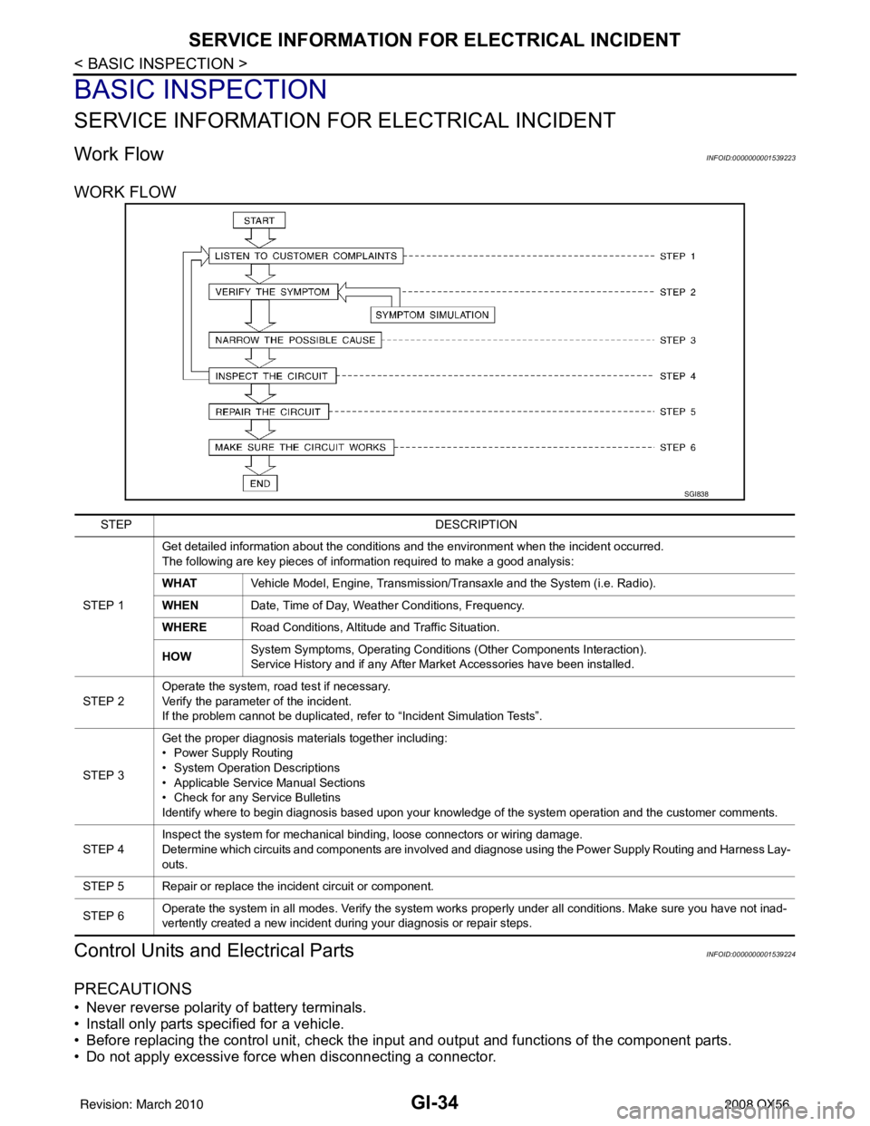
Work FlowINFOID:0000000001539223
WORK FLOW
Control Units and Electrical PartsINFOID:0000000001539224
PRECAUTIONS
• Never reverse polarity of battery terminals.
• Install only parts specified for a vehicle.
• Before replacing the control unit, check the i nput and output and functions of the component parts.
• Do not apply excessive force when disconnecting a connector.
SGI838
STEP DESCRIPTION
STEP 1 Get detailed information about the conditions and the environment when the incident occurred.
The following are key pieces of information required to make a good analysis:
WHAT
Vehicle Model, Engine, Transmission/Transaxle and the System (i.e. Radio).
WHEN Date, Time of Day, Weather Conditions, Frequency.
WHERE Road Conditions, Altitude and Traffic Situation.
HOW System Symptoms, Operating Conditions
(Other Components Interaction).
Service History and if any After Market Accessories have been installed.
STEP 2 Operate the system, road test if necessary.
Verify the parameter of the incident.
If the problem cannot be duplicated, refer to “Incident Simulation Tests”.
STEP 3 Get the proper diagnosis materials together including:
• Power Supply Routing
• System Operation Descriptions
• Applicable Service Manual Sections
• Check for any Service Bulletins
Identify where to begin diagnosis based upon your knowledge of the system operation and the customer comments.
STEP 4 Inspect the system for mechanical binding, loose connectors or wiring damage.
Determine which circuits and components are involved and diagnose using the Power Supply Routing and Harness Lay-
outs.
STEP 5 Repair or replace the incident circuit or component.
STEP 6 Operate the system in all modes. Verify the system works properly under all conditions. Make sure you have not inad-
vertently created a new incident during your diagnosis or repair steps.
Revision: March 2010
2008 QX56
Page 2182 of 4083
GI-40
< BASIC INSPECTION >
SERVICE INFORMATION FOR ELECTRICAL INCIDENT
An unclamped or loose harness can cause wiring to be pinched by seat components (such as slide guides)
during vehicle vibration. If the wiring runs under s eating areas, inspect wire routing for possible damage or
pinching.
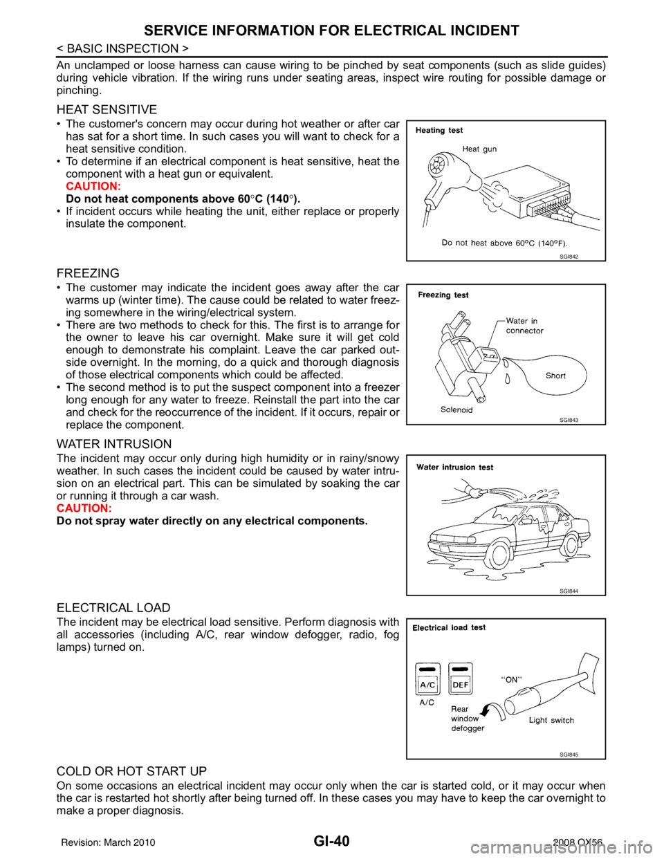
HEAT SENSITIVE
• The customer's concern may occur during hot weather or after car has sat for a short time. In such cases you will want to check for a
heat sensitive condition.
• To determine if an electrical component is heat sensitive, heat the component with a heat gun or equivalent.
CAUTION:
Do not heat components above 60 °C (140° ).
• If incident occurs while heating the unit, either replace or properly insulate the component.
FREEZING
• The customer may indicate the incident goes away after the carwarms up (winter time). The cause could be related to water freez-
ing somewhere in the wiring/electrical system.
• There are two methods to check for this. The first is to arrange for the owner to leave his car overnight. Make sure it will get cold
enough to demonstrate his complaint. Leave the car parked out-
side overnight. In the morning, do a quick and thorough diagnosis
of those electrical components which could be affected.
• The second method is to put the suspect component into a freezer long enough for any water to freeze. Reinstall the part into the car
and check for the reoccurrence of the incident. If it occurs, repair or
replace the component.
WATER INTRUSION
The incident may occur only during high humidity or in rainy/snowy
weather. In such cases the incident could be caused by water intru-
sion on an electrical part. This can be simulated by soaking the car
or running it through a car wash.
CAUTION:
Do not spray water directly on any electrical components.
ELECTRICAL LOAD
The incident may be electrical load sensitive. Perform diagnosis with
all accessories (including A/C, rear window defogger, radio, fog
lamps) turned on.
COLD OR HOT START UP
On some occasions an electrical incident may occur only when the car is started cold, or it may occur when
the car is restarted hot shortly after being turned off. In these cases you may have to keep the car overnight to
make a proper diagnosis.
SGI842
SGI843
SGI844
SGI845
Revision: March 2010 2008 QX56
Page 2188 of 4083
GI-46
< BASIC INSPECTION >
CONSULT-III CHECKING SYSTEM
CONSULT-III CHECKING SYSTEM
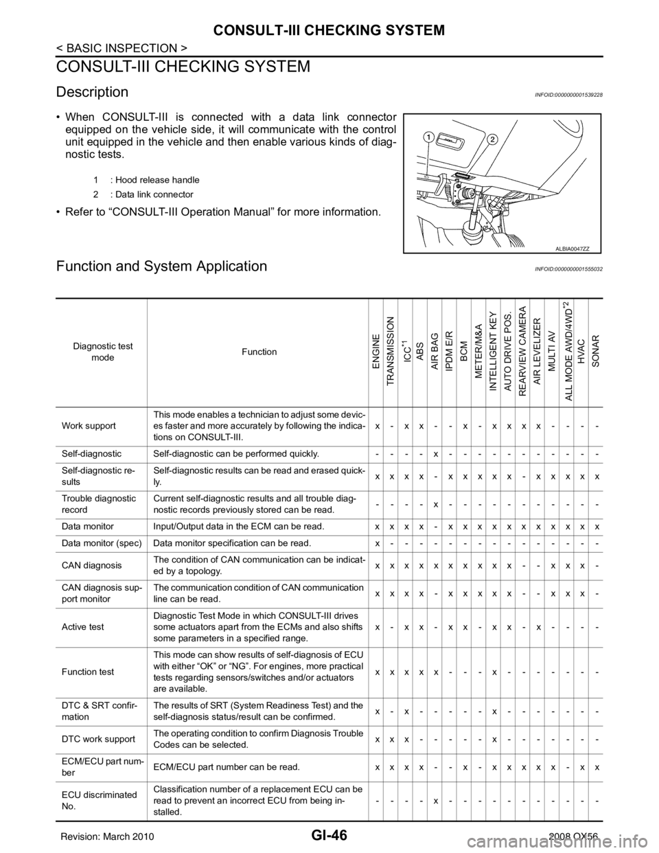
DescriptionINFOID:0000000001539228
• When CONSULT-III is connected with a data link connectorequipped on the vehicle side, it will communicate with the control
unit equipped in the vehicle and then enable various kinds of diag-
nostic tests.
• Refer to “CONSULT-III Operation Manual” for more information.
Function and System ApplicationINFOID:0000000001555032
1 : Hood release handle
2 : Data link connector
ALBIA0047ZZ
Diagnostic test mode Function
ENGINE
TRANSMISSION
ICC
*1
ABS
AIR BAG
IPDM E/R
BCM
METER/M&A
INTELLIGENT KEY
AUTO DRIVE POS.
REARVIEW CAMERA
AIR LEVELIZER MULTI AV
ALL MODE AWD/4WD
*2
HVAC
SONAR
Work support This mode enables a technician to adjust some devic-
es faster and more accurately by following the indica-
tions on CONSULT-III. x - xx - - x - xxxx - - - -
Self-diagnostic Self-diagnostic can be performed quickly. ----x-----------
Self-diagnostic re-
sults Self-diagnostic results can be read and erased quick-
ly.
xxxx - xxxxx - xxxxx
Trouble diagnostic
record Current self-diagnostic results and all trouble diag-
nostic records previously stored can be read.
--- - x--- - -------
Data monitor Input/Output data in the ECM can be read. xxxx - xxxxxxxxxxx
Data monitor (spec)Data monitor specification can be read. x---------------
CAN diagnosis The condition of CAN communication can be indicat-
ed by a topology.
xxxxxxxxxx - - xxx -
CAN diagnosis sup-
port monitor The communication condition of CAN communication
line can be read.
xxxx - xxxxx - - xxx -
Active test Diagnostic Test Mode in which CONSULT-III drives
some actuators apart from the ECMs and also shifts
some parameters in a specified range. x-xx-xx-xx-x- - - -
Function test This mode can show results of self-diagnosis of ECU
with either “OK” or “NG”. For engines, more practical
tests regarding sensors/switches and/or actuators
are available. xxxxx - - - x
-------
DTC & SRT confir-
mation The results of SRT (System Readiness Test) and the
self-diagnosis status/result can be confirmed.
x-x-----x-------
DTC work support The operating condition to confirm Diagnosis Trouble
Codes can be selected. xxx-----x-------
ECM/ECU part num-
ber ECM/ECU part number can be read.
xxxx - - x - xxxxx - xx
ECU discriminated
No. Classification number of a replacement ECU can be
read to prevent an incorrect ECU from being in-
stalled.
----x-----------
Revision: March 2010
2008 QX56
Page 2189 of 4083
CONSULT-III CHECKING SYSTEMGI-47
< BASIC INSPECTION >
C
DE
F
G H
I
J
K L
M B
GI
N
O P
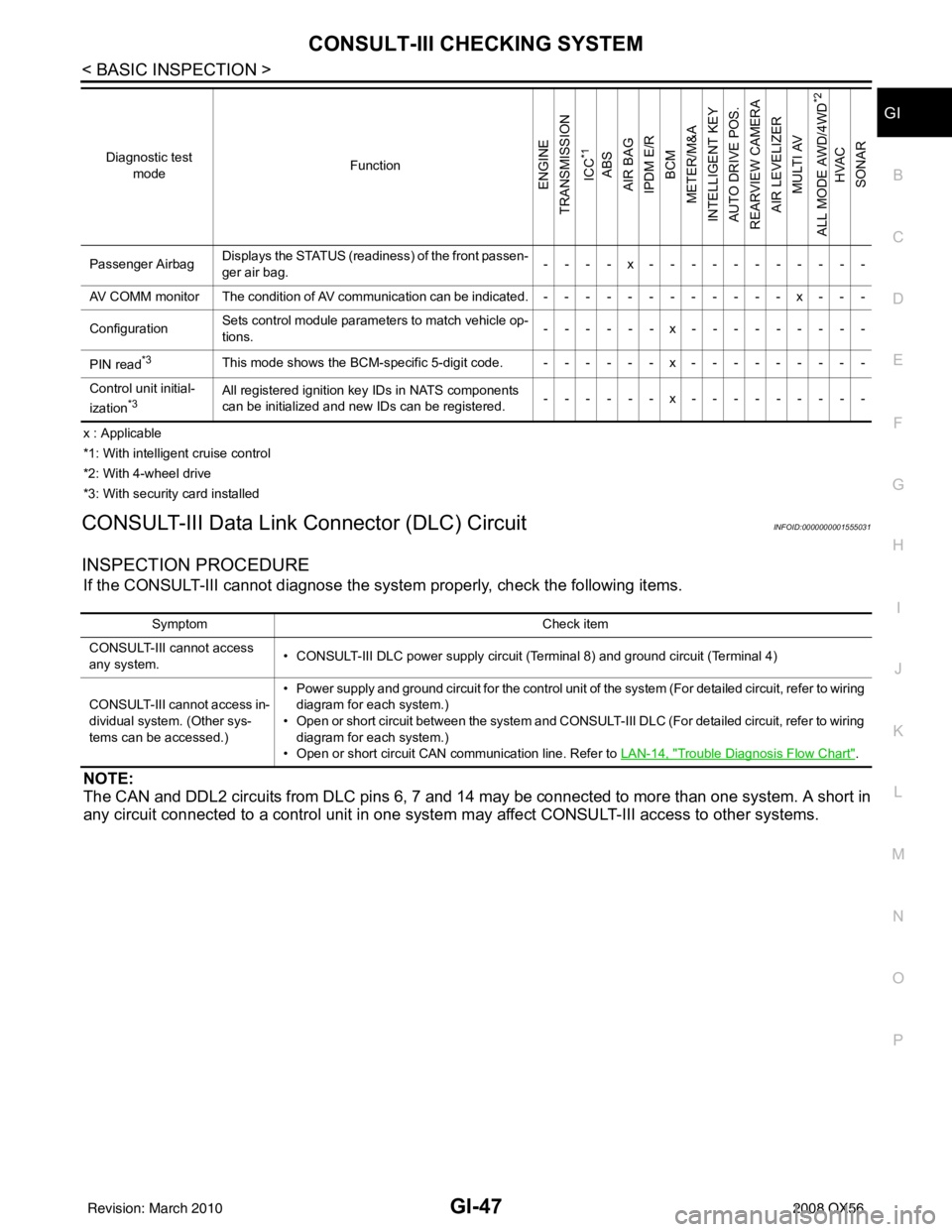
x : Applicable
*1: With intelligent cruise control
*2: With 4-wheel drive
*3: With security card installed
CONSULT-III Data Link Connector (DLC) CircuitINFOID:0000000001555031
INSPECTION PROCEDURE
If the CONSULT-III cannot diagnose the sys tem properly, check the following items.
NOTE:
The CAN and DDL2 circuits from DLC pins 6, 7 and 14 may be connected to more than one system. A short in
any circuit connected to a control unit in one system may affect CONSULT-III access to other systems.
Passenger AirbagDisplays the STATUS (readiness) of the front passen-
ger air bag. ----x-----------
AV COMM monitor The condition of AV communication can be indicated.------------x---
Configuration Sets control module parame
ters to match vehicle op-
tions. ------x---------
PIN read
*3This mode shows the BCM-specific 5-digit code. ------x---------
Control unit initial-
ization
*3All registered ignition key IDs in NATS components
can be initialized and new IDs can be registered. ------x---------
Diagnostic test
mode Function
ENGINE
TRANSMISSION
ICC
*1
ABS
AIR BAG
IPDM E/R BCM
METER/M&A
INTELLIGENT KEY
AUTO DRIVE POS.
REARVIEW CAMERA AIR LEVELIZER MULTI AV
ALL MODE AWD/4WD
*2
HVAC
SONAR
Symptom Check item
CONSULT-III cannot access
any system. • CONSULT-III DLC power supply circuit (Terminal 8) and ground circuit (Terminal 4)
CONSULT-III cannot access in-
dividual system. (Other sys-
tems can be accessed.) • Power supply and ground circuit for the control unit of the system (For detailed circuit, refer to wiring
diagram for each system.)
• Open or short circuit between the system and CONSULT-III DLC (For detailed circuit, refer to wiring diagram for each system.)
• Open or short circuit CAN communication line. Refer to LAN-14, "
Trouble Diagnosis Flow Chart".
Revision: March 2010 2008 QX56
Page 2200 of 4083
GW-10
< ON-VEHICLE REPAIR >
FRONT DOOR GLASS AND REGULATOR
NOTE:
If any of the following work has been done, reset the power window motor limit switch.
• Removal and installation of the regulator assembly.
• Removal and installation of the power window motor from the regulator.
• Installation of a new glass window.
• Installation of a new glass run.
Check the label on the power window motor for the part number. If the power window motor part number
matches one of the following, the motor must be removed from the regulator and the limit switch reset using
the "INSTALLATION WITHOUT RESET SWITCH" pr ocedure in "FRONT DOOR GLASS REGULATOR
ASSEMBLY".
• 80730-ZT01A
• 80731-ZT01A
• 80730-ZM70B
• 80731-ZM70B
If the power window motor part number does not match one of the part numbers above, the limit switch can be
reset in the vehicle using the "INSTA LLATION WITH RESET SWITCH" procedure.
NOTE:
• The label can be checked with the power window motor in the vehicle by using a mirror.
• Some of the power window motors with the part num bers above may appear to have a reset switch, but it will
not reset the limit switch.
Fitting Inspection
• Check that the glass is securely fit into the glass run groove.
• Lower the glass slightly [approximately 10 to 20 mm (0 .39 to 0.79 in)] and check that the clearance to the
sash is parallel. If the clearance between the glass and sash is not parallel, loosen the regulator bolts, guide
rail bolts, and glass and guide rail bolts to correct the glass position.
FRONT DOOR GLASS REGULATOR ASSEMBLY
Removal
1. Remove the front door finisher panel. Refer to INT-11, "Removal and Installation".
2. Position aside the vapor barrier.
3. Remove the hole cover over rear glass bolt.
4. Operate the power window main switch to raise/ lower the door window until the glass bolts can be seen.
5. Remove the inside seal.
6. Remove the glass bolts.
7. Raise the front door glass and hold it in place with suitable tool.
8. Disconnect the harness connector fr om the regulator assembly.
9. Remove the bolts and the regulator assembly.
Disassembly And Assembly
Remove the regulator motor from the regulator assembly.
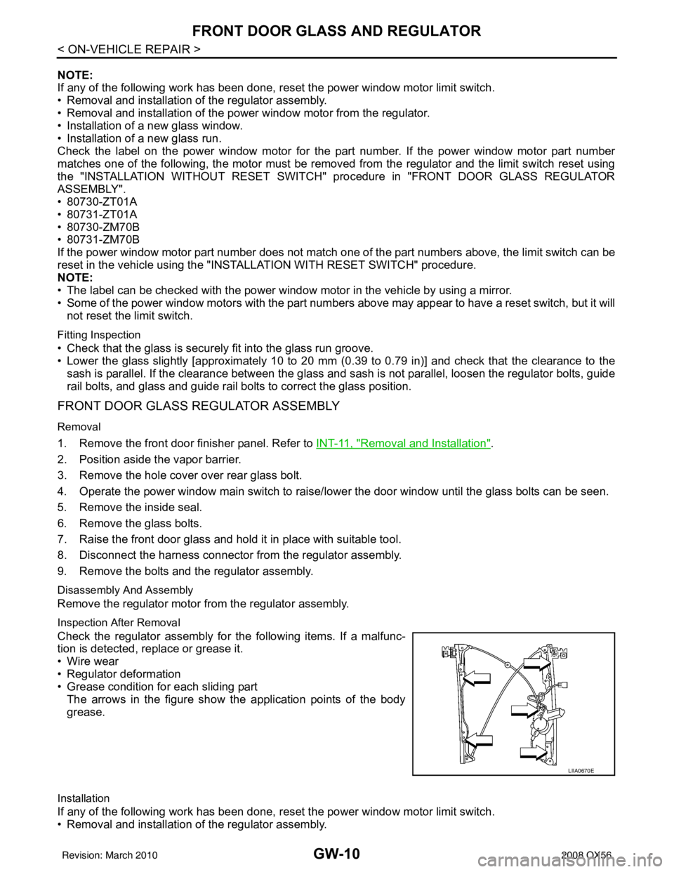
Inspection After Removal
Check the regulator assembly for the following items. If a malfunc-
tion is detected, replace or grease it.
• Wire wear
• Regulator deformation
• Grease condition for each sliding part The arrows in the figure show the application points of the body
grease.
Installation
If any of the following work has been done, reset the power window motor limit switch.
• Removal and installation of the regulator assembly.
LIIA0670E
Revision: March 2010 2008 QX56
Page 2204 of 4083
GW-14
< ON-VEHICLE REPAIR >
REAR DOOR GLASS AND REGULATOR
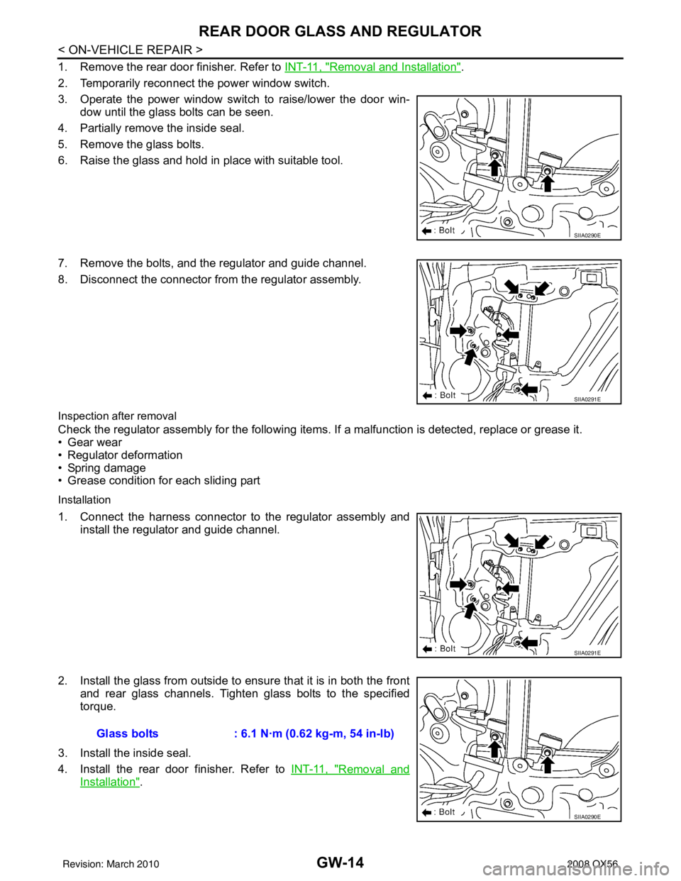
1. Remove the rear door finisher. Refer to INT-11, "Removal and Installation".
2. Temporarily reconnect the power window switch.
3. Operate the power window switch to raise/lower the door win- dow until the glass bolts can be seen.
4. Partially remove the inside seal.
5. Remove the glass bolts.
6. Raise the glass and hold in place with suitable tool.
7. Remove the bolts, and the regulator and guide channel.
8. Disconnect the connector from the regulator assembly.
Inspection after removal
Check the regulator assembly for the following items. If a malfunction is detected, replace or grease it.
• Gear wear
• Regulator deformation
• Spring damage
• Grease condition for each sliding part
Installation
1. Connect the harness connector to the regulator assembly and
install the regulator and guide channel.
2. Install the glass from outside to ensure that it is in both the front and rear glass channels. Tighten glass bolts to the specified
torque.
3. Install the inside seal.
4. Install the rear door finisher. Refer to INT-11, "
Removal and
Installation".
SIIA0290E
SIIA0291E
SIIA0291E
Glass bolts: 6.1 N·m (0.62 kg-m, 54 in-lb)
SIIA0290E
Revision: March 2010 2008 QX56