2008 INFINITI QX56 diagram
[x] Cancel search: diagramPage 3348 of 4083
SN
SONAR CONTROL UNIT FOR REAR SONAR SYSTEMSN-23
< ECU DIAGNOSIS >
C
DE
F
G H
I
J
K L
M B A
O P
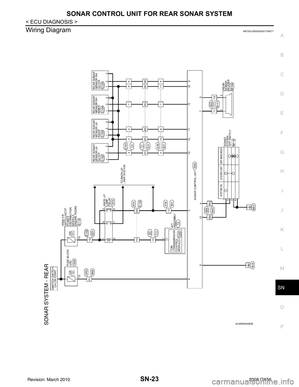
Wiring DiagramINFOID:0000000001754071
ALNWA0049GB
Revision: March 2010 2008 QX56
Page 3358 of 4083
SN
SONAR CONTROL UNIT FOR FRONT AND REAR SONAR SYSTEMSN-33
< ECU DIAGNOSIS >
C
DE
F
G H
I
J
K L
M B A
O P
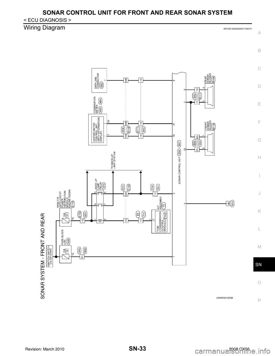
Wiring DiagramINFOID:0000000001754074
AANWA0120GB
Revision: March 2010 2008 QX56
Page 3399 of 4083

SRC-1
RESTRAINTS
C
DE
F
G
I
J
K L
M
SECTION SRC
A
B
SRC
N
O P
CONTENTS
SRS AIRBAG CONTROL SYSTEM
BASIC INSPECTION ....... .............................3
DIAGNOSIS AND REPAIR WORK FLOW .... .....3
Work Flow ........................................................... ......3
INTERMITTENTS INCIDENT ..............................5
Inspection Procedure ......................................... ......5
Trouble Diagnosis with CONSULT-III .......................5
FUNCTION DIAGNOSIS ...............................6
SRS AIR BAG SYSTEM ................................. .....6
SRS Configuration .............................................. ......6
SRS Component Parts Location ...............................7
Driver Air Bag Module ...............................................7
Front Passenger Air Bag Module ..............................8
Front Side Air Bag ............................................... ......8
Side Curtain Air Bag ..................................................8
Front Seat Belt Pre-tensioner with Load Limiter .......8
Direct-connect SRS Component Connectors ............9
OCCUPANT CLASSIFICATION SYSTEM .........10
System Diagram .................................................. ....10
Occupant Classification System (OCS) ..................10
PASSENGER SEAT BELT WARNING SYS-
TEM ....................................................................
12
System Diagram .................................................. ....12
System Description .................................................12
Component Parts Location ......................................12
ON BOARD DIAGNOSTIC (OBD) SYSTEM ......13
Trouble Diagnosis Introduction ........................... ....13
SRS Operation Check .............................................13
Trouble Diagnosis without CONSULT-III ................15
CONSULT-III Function (AIR BAG) ..........................15
Self-Diagnosis Function (Without CONSULT-III) ....15
COMPONENT DIAGNOSIS .........................17
B1049 – B1052, B1054 – B1057 DRIVER AIR-
BAG MODULE ...................................................
17
Description ........................................................... ....17
DTC Logic ................................................................17
Diagnosis Procedure (Component Diagnosis) ........18
B1065 – B1068, B1070 – B1073 PASSEN-
GER AIRBAG MODULE ...................................
20
Description ...............................................................20
DTC Logic ................................................................20
Diagnosis Procedure (Component Diagnosis) ........21
B1134 – B1137 SIDE AIRBAG MODULE LH ...23
Description ...............................................................23
DTC Logic ................................................................23
Diagnosis Procedure (Component Diagnosis) ........24
B1129 – B1132 SIDE AIRBAG MODULE RH ...26
Description ...............................................................26
DTC Logic ................................................................26
Diagnosis Procedure (Component Diagnosis) ........27
B1198 – B1201 SIDE CURTAIN AIR BAG
MODULE LH (FRONT) ......................................
29
Description ...............................................................29
DTC Logic ................................................................29
Diagnosis Procedure (Component Diagnosis) ........30
B1193 – B1196 SIDE CURTAIN AIR BAG
MODULE RH (FRONT) .....................................
32
Description ...............................................................32
DTC Logic ................................................................32
Diagnosis Procedure (Component Diagnosis) ........33
B1150 – B1153 SIDE CURTAIN AIR BAG
MODULE LH (REAR) ........................................
35
Description ...............................................................35
DTC Logic ................................................................35
Diagnosis Procedure (Component Diagnosis) ........36
B1145 – B1148 SIDE CURTAIN AIR BAG
MODULE RH (REAR) .......................................
38
Description ...............................................................38
DTC Logic ................................................................38
Revision: March 2010 2008 QX56
Page 3400 of 4083

SRC-2
Diagnosis Procedure (Component Diagnosis) ........39
B1086 – B1089 SEAT BELT PRE-TENSION-
ER LH .................................................................
41
Description ........................................................... ...41
DTC Logic ...............................................................41
Diagnosis Procedure (Component Diagnosis) ........42
B1081 – B1084 SEAT BELT PRE-TENSION-
ER RH ................................................................
44
Description ..............................................................44
DTC Logic ...............................................................44
Diagnosis Procedure (Component Diagnosis) ........45
B1182 - B1185 SEAT BELT BUCKLE PRE-
TENSIONER LH .................................................
47
Description ........................................................... ...47
DTC Logic ...............................................................47
Diagnosis Procedure (Component Diagnosis) ........48
B1177 - B1180 SEAT BELT BUCKLE PRE-
TENSIONER RH ................................................
50
Description ........................................................... ...50
DTC Logic ...............................................................50
Diagnosis Procedure (Component Diagnosis) ........51
B1033 – B1035 CRASH ZONE SENSOR .........53
Description ........................................................... ...53
DTC Logic ...............................................................53
Diagnosis Procedure (Component Diagnosis) ........54
B1118 – B1120 SATELLITE SENSOR LH ........56
Description ........................................................... ...56
DTC Logic ...............................................................56
Diagnosis Procedure (Component Diagnosis) ........57
B1113 – B1115 SATELLITE SENSOR RH .......59
Description ........................................................... ...59
DTC Logic ...............................................................59
Diagnosis Procedure (Component Diagnosis) ........60
B1XXX AIR BAG DIAGNOSIS SENSOR UNIT ...62
Description ........................................................... ...62
DTC Logic ...............................................................62
Diagnosis Procedure (Component Diagnosis) ........63
B1023 PASSENGER AIR BAG OFF INDICA-
TOR ....................................................................
64
Description ........................................................... ...64
DTC Logic ...............................................................64
Diagnosis Procedure (Component Diagnosis) ........65
B1017 – B1022 OCCUPANT CLASSIFICA-
TION SYSTEM ................................................ ...
67
Description ........................................................... ...67
DTC Logic ...............................................................67
Diagnosis Procedure (Component Diagnosis) ........68
B1209 – B1211 COLLISION DETECTION ........71
Description ........................................................... ...71
DTC Logic ...............................................................71
Diagnosis Procedure (Component Diagnosis) ........71
ECU DIAGNOSIS .......................................72
DIAGNOSIS SENSOR UNIT .............................72
Wiring Diagram .................................................... ...72
Trouble Diagnosis with CONSULT-III .....................81
Trouble Diagnosis without CONSULT-III ................85
SYMPTOM DIAGNOSIS ............................90
SRS AIR BAG SYSTEM ................................. ...90
"AIR BAG" Warning Lamp Does Not Turn Off ..... ...90
"AIR BAG" Warning Lamp Does Not Turn On ........90
PASSENGER SEAT BELT WARNING SYS-
TEM ....................................................................
92
Seat Belt Warning System Does Not Function .... ...92
PRECAUTION ............................................93
PRECAUTIONS .............................................. ...93
Precaution for Supplemental Restraint System
(SRS) "AIR BAG" and "SEAT BELT PRE-TEN-
SIONER" .............................................................. ...
93
Precaution for SRS "AIR BAG" and "SEAT BELT
PRE-TENSIONER" Service ................................. ...
93
Occupant Classification System Precaution ...........93
Revision: March 2010 2008 QX56
Page 3408 of 4083
SRC-10
< FUNCTION DIAGNOSIS >
OCCUPANT CLASSIFICATION SYSTEM
OCCUPANT CLASSIFICATION SYSTEM
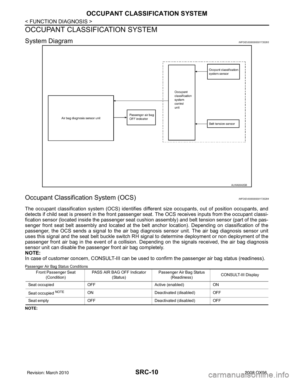
System DiagramINFOID:0000000001735293
Occupant Classification System (OCS)INFOID:0000000001735294
The occupant classification system (OCS) identifies different size occupants, out of position occupants, and
detects if child seat is present in the front passenger seat. The OCS receives inputs from the occupant classi-
fication sensor (located inside the passenger seat cushion assembly) and belt tension sensor (part of the pas-
senger front seat belt assembly and located at the belt anchor location). Depending on classification of the
passenger, the OCS sends a signal to the air bag diagnos is sensor unit. The air bag diagnosis sensor unit
uses this signal and the seat belt buckle switch RH signal to determine deployment or non deployment of the
passenger front air bag in the event of a collision. Depending on the signals received, the air bag diagnosis
sensor unit can disable the passenger front air bag completely.
NOTE:
In case of customer concern, CONSULT-III can be used to confirm the passenger air bag status (readiness).
Passenger Air Bag Status Conditions
NOTE:
ALHIA0042GB
Front Passenger Seat
(Condition) PASS AIR BAG OFF Indicator
(Status) Passenger Air Bag Status
(Readiness) CONSULT-III Display
Seat occupied OFF Active (enabled)ON
Seat occupied
NOTEON Deactivated (disabled) OFF
Seat empty OFF Deactivated (disabled) OFF
Revision: March 2010 2008 QX56
Page 3410 of 4083
SRC-12
< FUNCTION DIAGNOSIS >
PASSENGER SEAT BELT WARNING SYSTEM
PASSENGER SEAT BELT WARNING SYSTEM
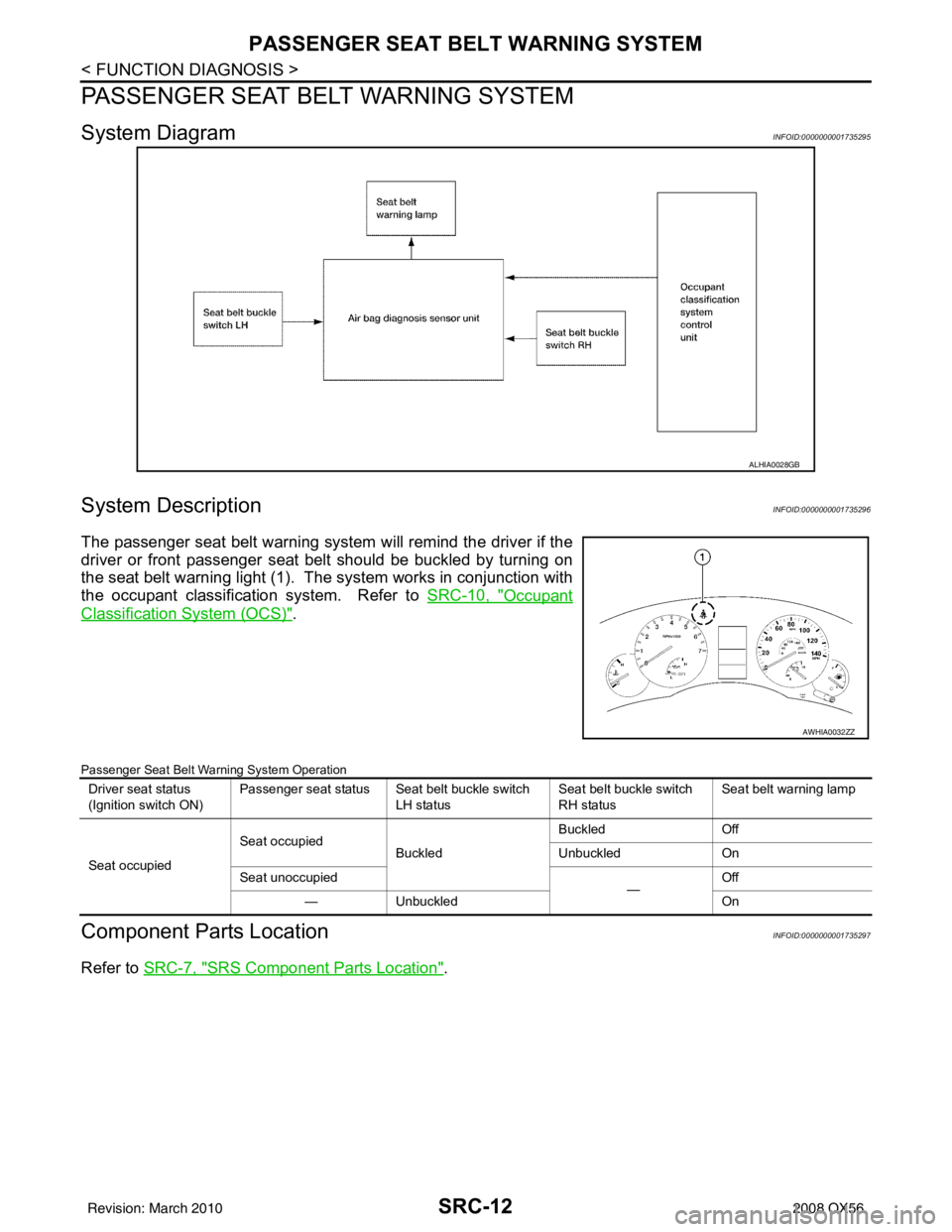
System DiagramINFOID:0000000001735295
System DescriptionINFOID:0000000001735296
The passenger seat belt warning system will remind the driver if the
driver or front passenger seat belt should be buckled by turning on
the seat belt warning light (1). The system works in conjunction with
the occupant classification system. Refer to SRC-10, "
Occupant
Classification System (OCS)".
Passenger Seat Belt Warning System Operation
Component Parts LocationINFOID:0000000001735297
Refer to SRC-7, "SRS Component Parts Location".
ALHIA0028GB
AWHIA0032ZZ
Driver seat status
(Ignition switch ON) Passenger seat status Seat belt buckle switch
LH status Seat belt buckle switch
RH statusSeat belt warning lamp
Seat occupied Seat occupied
Buckled Buckled
Off
Unbuckled On
Seat unoccupied —Off
— Unbuckled On
Revision: March 2010 2008 QX56
Page 3470 of 4083
SRC-72
< ECU DIAGNOSIS >
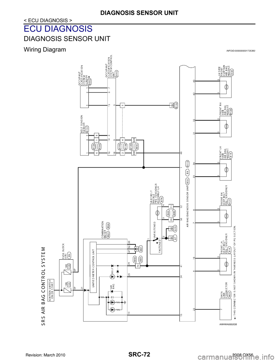
DIAGNOSIS SENSOR UNIT
ECU DIAGNOSIS
DIAGNOSIS SENSOR UNIT
Wiring DiagramINFOID:0000000001735360
AWHWA0002GB
Revision: March 20102008 QX56
Page 3492 of 4083

ST-1
STEERING
C
DE
F
H I
J
K L
M
SECTION ST
A
B
ST
N
O P
CONTENTS
STEERING SYSTEM
PRECAUTION ....... ........................................3
PRECAUTIONS .............................................. .....3
Precaution for Supplemental Restraint System
(SRS) "AIR BAG" and "SEAT BELT PRE-TEN-
SIONER" ............................................................. ......
3
Precaution Necessary for Steering Wheel Rota-
tion After Battery Disconnect ............................... ......
3
Precaution for Steering System .......................... ......4
PREPARATION ............................................5
PREPARATION .............................................. .....5
Special Service Tool ........................................... ......5
Commercial Service Tool ..........................................6
FUNCTION DIAGNOSIS ...............................7
HEATED STEERING WHEEL ........................ .....7
System Diagram .................................................. ......7
System Description ...................................................7
Component Parts Location ........................................7
Component Description .............................................8
COMPONENT DIAGNOSIS ..........................9
HEATED STEERING WHEEL ........................ .....9
Wiring Diagram ................................................... ......9
SYMPTOM DIAGNOSIS ..............................12
NOISE, VIBRATION AND HARSHNESS
(NVH) TROUBLESHOOTING ........................ ....
12
NVH Troubleshooting Chart ................................ ....12
ON-VEHICLE MAINTENANCE ....................13
POWER STEERING FLUID ........................... ....13
Checking Fluid Level ........................................... ....13
Checking Fluid Leakage ..........................................13
Air Bleeding Hydraulic System ................................13
ON-VEHICLE REPAIR .................................15
STEERING WHEEL ..........................................15
On-Vehicle Inspection and Service ..................... ....15
POWER STEERING OIL PUMP .......................17
On-Vehicle Inspection and Service .........................17
REMOVAL AND INSTALLATION ...............18
STEERING WHEEL ..........................................18
Removal and Installation ..................................... ....18
TILT SYSTEM ...................................................19
Removal and Installation .........................................19
STEERING COLUMN ........................................20
Removal and Installation .........................................20
POWER STEERING GEAR AND LINKAGE ....23
Removal and Installation .........................................23
POWER STEERING OIL PUMP .......................26
Removal and Installation .........................................26
HYDRAULIC LINE ............................................27
Removal and Installation .........................................27
DISASSEMBLY AND ASSEMBLY ..............29
STEERING COLUMN ........................................29
Disassembly and Assembly ................................. ....29
POWER STEERING GEAR AND LINKAGE ....31
Disassembly and Assembly .....................................31
POWER STEERING OIL PUMP .......................35
Disassembly and Assembly .....................................35
SERVICE DATA AND SPECIFICATIONS
(SDS) ............... .......................................... ...
36
SERVICE DATA AND SPECIFICATIONS
(SDS) .................................................................
36
Steering Wheel .................................................... ....36
Revision: March 2010 2008 QX56