2008 INFINITI QX56 diagram
[x] Cancel search: diagramPage 2985 of 4083
RF-1
BODY EXTERIOR, DOORS, ROOF & VEHICLE SECURITY
C
DE
F
G H
I
J
L
M
SECTION RF
A
B
RF
N
O P
CONTENTS
ROOF
BASIC INSPECTION ....... .............................3
DIAGNOSIS AND REPAIR WORKFLOW ..... .....3
Work Flow ........................................................... ......3
INSPECTION AND ADJUSTMENT .....................5
ADDITIONAL SERVICE WHEN REPLACING
CONTROL UNIT .................................................... ......
5
ADDITIONAL SERVICE WHEN REPLACING
CONTROL UNIT : Description ..................................
5
ADDITIONAL SERVICE WHEN REPLACING
CONTROL UNIT : Special Repair Requirement .......
5
BASIC INSPECTION ...................................................5
BASIC INSPECTION : Spec ial Repair Require-
ment .................................................................... ......
5
FUNCTION DIAGNOSIS ...............................6
SUNROOF SYSTEM ...................................... .....6
System Diagram ................................................. ......6
System Description ...................................................6
Component Parts Location ......................................7
Component Description ............................................7
DIAGNOSIS SYSTEM (BCM) .............................8
COMMON ITEM ..................................................... ......8
COMMON ITEM : CONSULT-III Function (BCM -
COMMON ITEM) .......................................................
8
RETAINED PWR .........................................................8
RETAINED PWR : CONSULT-III Function (BCM -
RETAINED PWR) .....................................................
8
COMPONENT DIAGNOSIS .........................10
POWER SUPPLY AND GROUND CIRCUIT .. ....10
SUNROOF MOTOR ASSEMBLY .......................... ....10
SUNROOF MOTOR ASSEMBLY :
Diagnosis Procedure ..............................................
10
SUNROOF MOTOR ASSEMBLY : Special Repair
Requirement ........................................................ ....
11
SUNROOF SWITCH CIRCUIT ..........................12
Description ...............................................................12
Component Function Check ..................................12
Diagnosis Procedure ...............................................12
DOOR SWITCH .................................................14
Description ...............................................................14
Component Function Check ....................................14
Diagnosis Procedure ...............................................14
Component Inspection .............................................15
ECU DIAGNOSIS .........................................16
BCM (BODY CONTROL MODULE) .................16
Reference Value .................................................. ....16
Terminal Layout .......................................................18
Physical Values ................................................... ....18
Wiring Diagram ........................................................24
Fail Safe ..................................................................27
DTC Inspection Priority Chart ...............................28
DTC Index ...............................................................28
SUNROOF SYSTEM .........................................30
Reference Value ......................................................30
Wiring Diagram ........................................................31
SYMPTOM DIAGNOSIS ..............................35
SUNROOF DOES NOT OPERATE PROPER-
LY ......................................................................
35
Diagnosis Procedure ........................................... ....35
AUTO OPERATION DOES NOT OPERATE ....36
Diagnosis Procedure ...............................................36
DOES NOT STOP FULLY-OPEN OR FULLY-
CLOSED POSITION ..........................................
37
Diagnosis Procedure ...............................................37
Revision: March 2010 2008 QX56
Page 2990 of 4083
RF-6
< FUNCTION DIAGNOSIS >
SUNROOF SYSTEM
FUNCTION DIAGNOSIS
SUNROOF SYSTEM
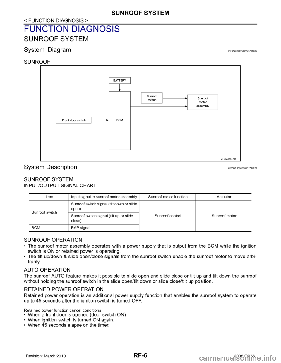
System DiagramINFOID:0000000001731922
SUNROOF
System DescriptionINFOID:0000000001731923
SUNROOF SYSTEM
INPUT/OUTPUT SIGNAL CHART
SUNROOF OPERATION
• The sunroof motor assembly operates with a power supply that is output from the BCM while the ignition
switch is ON or retained power is operating.
• The tilt up/down & slide open/close signals from the sunr oof switch enable the sunroof motor to move arbi-
trarily.
AUTO OPERATION
The sunroof AUTO feature makes it possible to sli de open and slide close or tilt up and tilt down the sunroof
without holding the sunroof switch in the slide open/tilt down or slide close/tilt up position.
RETAINED POWER OPERATION
Retained power operation is an additional power supply function that enables the sunroof system to operate
up to 45 seconds after the ignition switch is turned OFF.
Retained power function cancel conditions
• When a front door is opened (door switch ON)
• When ignition switch is turned ON again.
• When 45 seconds elapse on the timer.
ALKIA0861GB
Item Input signal to sunroof motor assembly Sunroof motor function Actuator
Sunroof switch Sunroof switch signal (tilt down or slide
open)
Sunroof controlSunroof motor
Sunroof switch signal (tilt up or slide
close)
BCM RAP signal
Revision: March 2010 2008 QX56
Page 3008 of 4083
RF-24
< ECU DIAGNOSIS >
BCM (BODY CONTROL MODULE)
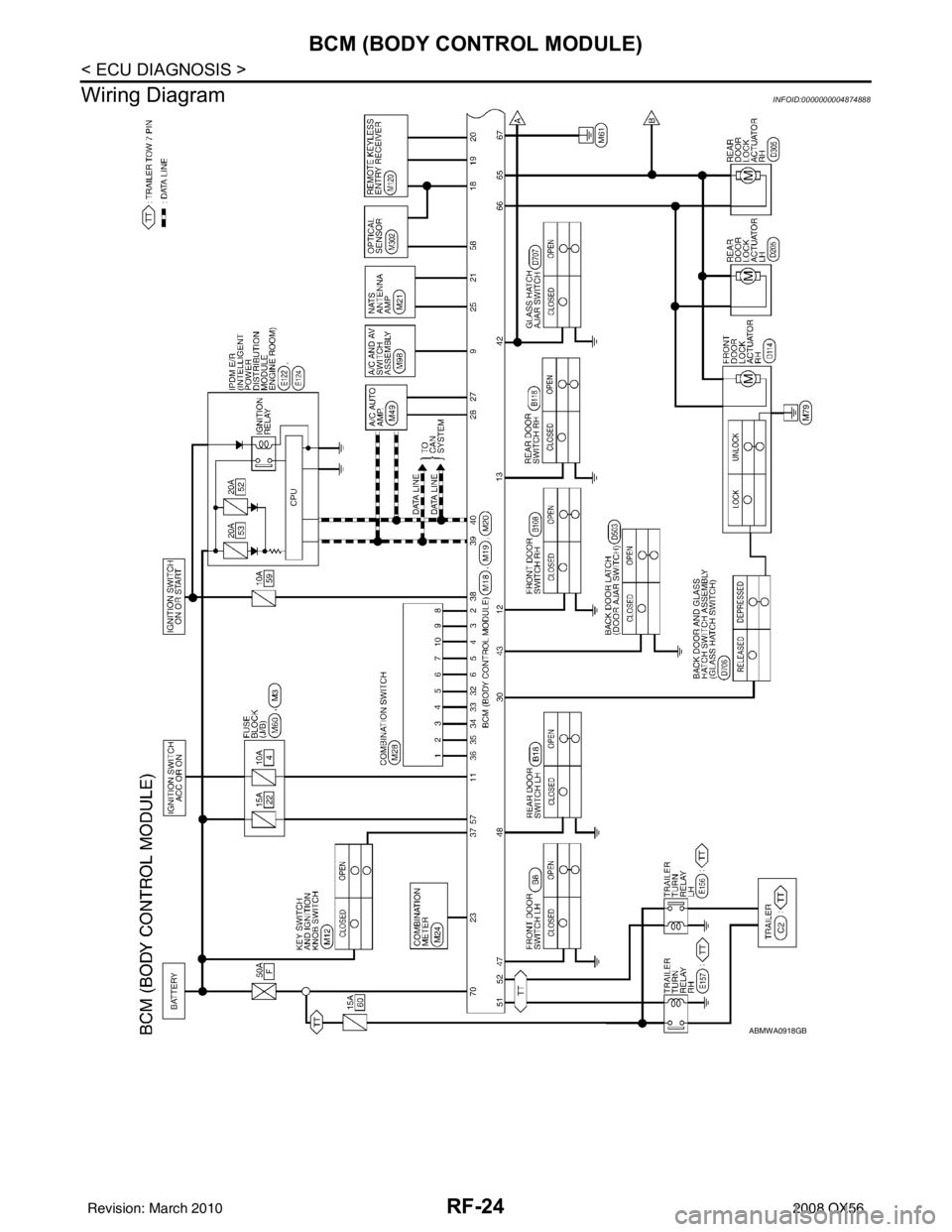
Wiring Diagram
INFOID:0000000004874888
ABMWA0918GB
Revision: March 2010 2008 QX56
Page 3015 of 4083

SUNROOF SYSTEMRF-31
< ECU DIAGNOSIS >
C
DE
F
G H
I
J
L
M A
B
RF
N
O P
Wiring DiagramINFOID:0000000001731938
AAKWA0138GB
Revision: March 2010 2008 QX56
Page 3084 of 4083
SCS-1
SUSPENSION
C
DF
G H
I
J
K L
M
SECTION SCS
A
B
SCS
N
O PCONTENTS
SUSPENSION CONTROL SYSTEM
BASIC INSPECTION ....... .............................3
DIAGNOSIS AND REPAIR WORKFLOW ..... .....3
Work Flow ........................................................... ......3
FUNCTION DIAGNOSIS ...............................5
SUSPENSION CONTROL SYSTEM .............. .....5
System Diagram .................................................. ......5
System Description ...................................................5
Component Parts Location ........................................6
Component Description .............................................6
DIAGNOSIS SYSTEM (SUSPENSION CON-
TROL UNIT) .........................................................
7
CONSULT-III Function ..............................................7
COMPONENT DIAGNOSIS ..........................9
C1801 VEHICLE HEIGHT SENSOR .............. .....9
Description .......................................................... ......9
DTC Logic .................................................................9
Diagnosis Procedure ................................................9
C1802 COMPRESSOR RELAY .........................10
Description ..............................................................10
DTC Logic ...............................................................10
Diagnosis Procedure ..............................................10
C1803 EXHAUST SOLENOID ...........................11
Description ..............................................................11
DTC Logic ...............................................................11
Diagnosis Procedure ..............................................11
C1804 HEIGHT ADJUSTING MALFUNCTION
(COMPRESSOR) ............................................ ....
12
Description .......................................................... ....12
DTC Logic ...............................................................12
Diagnosis Procedure ..............................................12
C1805 HEIGHT ADJUSTING MALFUNCTION
(EXH SOLENOID) ..............................................
13
Description ........................................................... ....13
DTC Logic ................................................................13
Diagnosis Procedure ..............................................13
C1806 VEHICLE HEIGHT SENSOR LOCK-
ING MALFUNCTION .........................................
14
Description ........................................................... ....14
DTC Logic ................................................................14
Diagnosis Procedure ...............................................14
C1807 SENSOR 5V MALFUNCTION ...............15
Description ...............................................................15
DTC Logic ................................................................15
Diagnosis Procedure ..............................................15
C1808 INTEGRAL TIME MALFUNCTION
SUPPLYING AIR ...............................................
16
Description ...............................................................16
DTC Logic ................................................................16
Diagnosis Procedure ..............................................16
POWER SUPPLY AND GROUND CIRCUIT ....17
SUSPENSION CONTROL UNIT ................................17
SUSPENSION CONTROL UNI T : Diagnosis Pro-
cedure .................................................................. ....
17
SUSPENSION AIR COMPRESSOR ..........................17
SUSPENSION AIR COMPRESSOR : Diagnosis
Procedure ............................................................ ....
17
HEIGHT SENSOR .................................................. ....18
HEIGHT SENSOR : Diagnosis Procedure ..............18
COMPRESSOR MOTOR RELAY .....................20
Description ...............................................................20
Component Function Check ....................................20
Diagnosis Procedure ...............................................20
HEIGHT SENSOR SIGNAL CIRCUIT ...............22
Description ...............................................................22
Component Function Check ....................................22
Diagnosis Procedure ...............................................22
Revision: March 2010 2008 QX56
Page 3085 of 4083

SCS-2
EXHAUST VALVE SOLENOID CIRCUIT ..........23
Description ........................................................... ...23
Component Function Check ...................................23
Diagnosis Procedure ..............................................23
CK SUSP WARNING INDICATOR CONTROL
CIRCUIT .............................................................
25
Description ........................................................... ...25
Component Function Check ...................................25
Diagnosis Procedure ..............................................25
ECU DIAGNOSIS ..................................... ...27
SUSPENSION CONTROL UNIT ........................27
Reference Value .................................................. ...27
Wiring Diagram .......................................................28
DTC Index ..............................................................33
SYMPTOM DIAGNOSIS .............................35
SUSPENSION CONTROL SYSTEM .............. ...35
Symptom Table ................................................... ...35
SUSPENSION CONTROL SYSTEM INOPER-
ATIVE .................................................................
36
Description ........................................................... ...36
Diagnosis Procedure ...............................................36
SUSPENSION CONTROL SYSTEM DOES
NOT RAISE ........................................................
37
Description ........................................................... ...37
Diagnosis Procedure ...............................................37
SUSPENSION CONTROL SYSTEM DOES
NOT LOWER .....................................................
38
Description ........................................................... ...38
Diagnosis Procedure ...............................................38
PRECAUTION ............................................39
PRECAUTIONS .............................................. ...39
Precaution for Supplemental Restraint System
(SRS) "AIR BAG" and "SEAT BELT PRE-TEN-
SIONER" .............................................................. ...
39
Precaution for Rear Suspension .............................39
Revision: March 2010 2008 QX56
Page 3088 of 4083
SUSPENSION CONTROL SYSTEMSCS-5
< FUNCTION DIAGNOSIS >
C
DF
G H
I
J
K L
M A
B
SCS
N
O P
FUNCTION DIAGNOSIS
SUSPENSION CONTROL SYSTEM
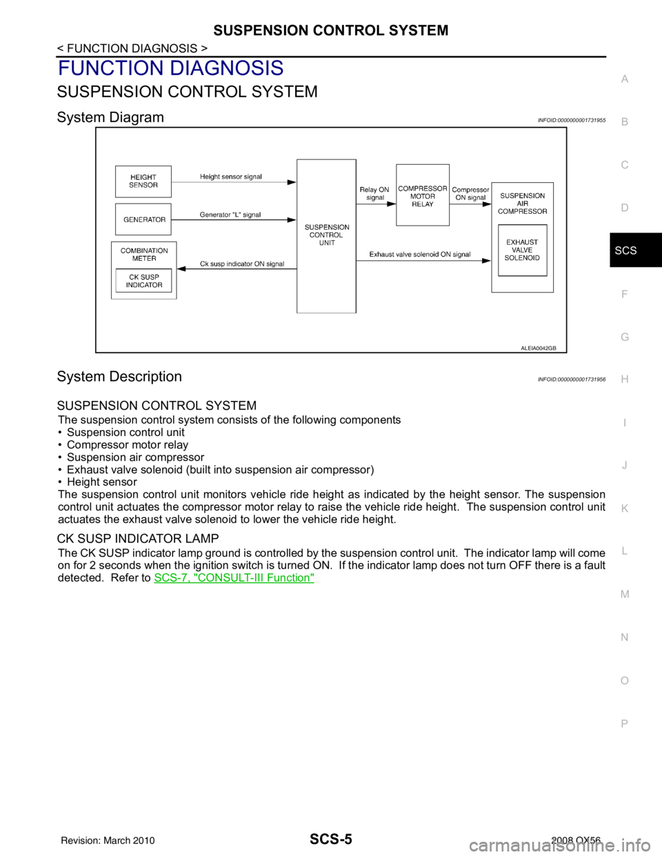
System DiagramINFOID:0000000001731955
System DescriptionINFOID:0000000001731956
SUSPENSION CONTROL SYSTEM
The suspension control system consists of the following components
• Suspension control unit
• Compressor motor relay
• Suspension air compressor
• Exhaust valve solenoid (built into suspension air compressor)
• Height sensor
The suspension control unit monitors vehicle ride height as indicated by the height sensor. The suspension
control unit actuates the compressor motor relay to ra ise the vehicle ride height. The suspension control unit
actuates the exhaust valve solenoid to lower the vehicle ride height.
CK SUSP INDICATOR LAMP
The CK SUSP indicator lamp ground is controlled by the suspension control unit. The indicator lamp will come
on for 2 seconds when the ignition switch is turned ON. If the indicator lamp does not turn OFF there is a fault
detected. Refer to SCS-7, "
CONSULT-III Function"
ALEIA0042GB
Revision: March 2010 2008 QX56
Page 3111 of 4083
SCS-28
< ECU DIAGNOSIS >
SUSPENSION CONTROL UNIT
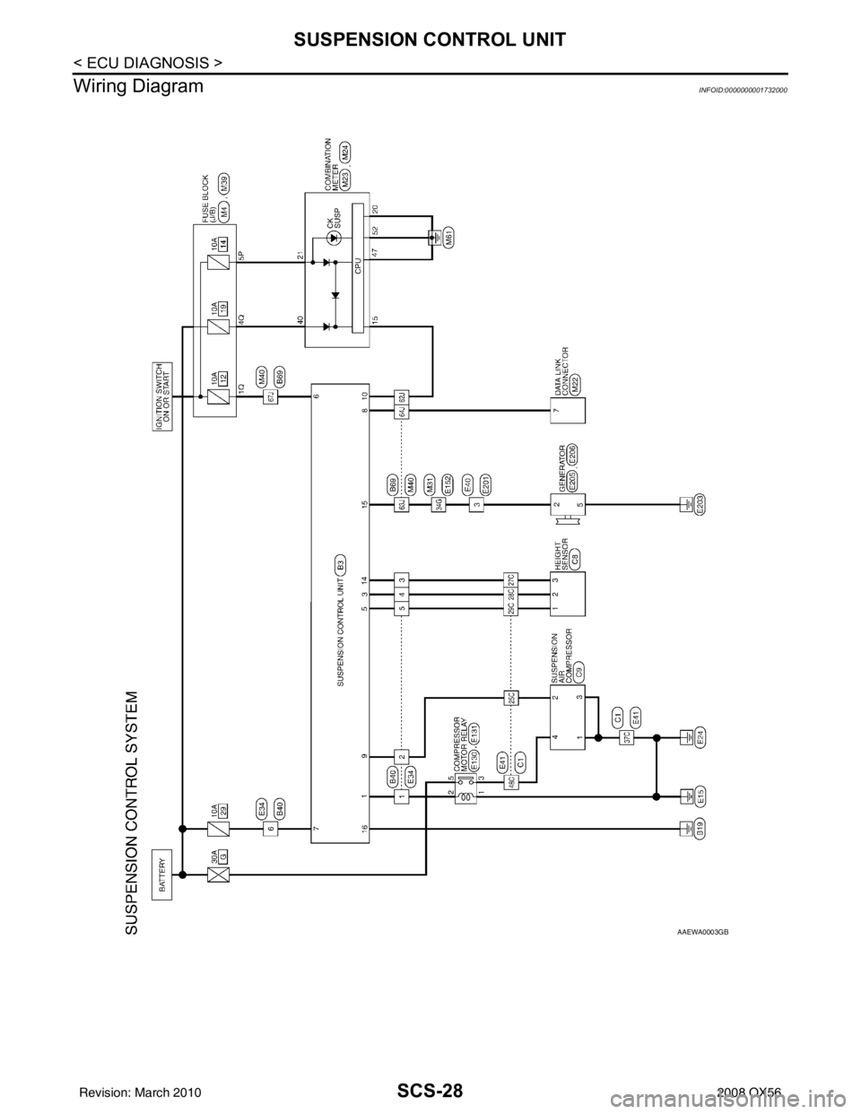
Wiring Diagram
INFOID:0000000001732000
AAEWA0003GB
Revision: March 2010 2008 QX56