2008 INFINITI QX56 Fuel
[x] Cancel search: FuelPage 2678 of 4083
MWI
FUEL LEVEL SENSOR SIGNAL CIRCUITMWI-33
< COMPONENT DIAGNOSIS >
C
DE
F
G H
I
J
K L
M B A
O P
FUEL LEVEL SENSOR SIGNAL CIRCUIT
DescriptionINFOID:0000000001691293
The fuel level sensor unit and fuel pump detects the approx imate fuel level in the fuel tank and transmits the
fuel level signal to the combination meter.
Component Function CheckINFOID:0000000001691294
1.COMBINATION METER INPUT SIGNAL
1. Select “METER/M&A” on CONSULT-III.
2. Using “FUEL METER” of “DATA MONITOR”, comp are the value of DATA MONITOR with fuel gauge
pointer of combination meter.
Does the data monitor value approximately match the fuel gauge indication?
YES >> Inspection End.
NO >> Replace combination meter. Refer to MWI-76, "
Removal and Installation".
Diagnosis ProcedureINFOID:0000000001691295
1.CHECK HARNESS CONNECTOR
1. Turn ignition switch OFF.
2. Check combination meter and fuel level sensor unit terminals (meter-side and harness-side) for poor con- nection.
Is the inspection result normal?
YES >> GO TO 2
NO >> Repair or replace terminals or connectors.
2.CHECK FUEL LEVEL SENSOR UNIT CIRCUIT
1. Disconnect combination meter connector and fuel level sensor unit connector.
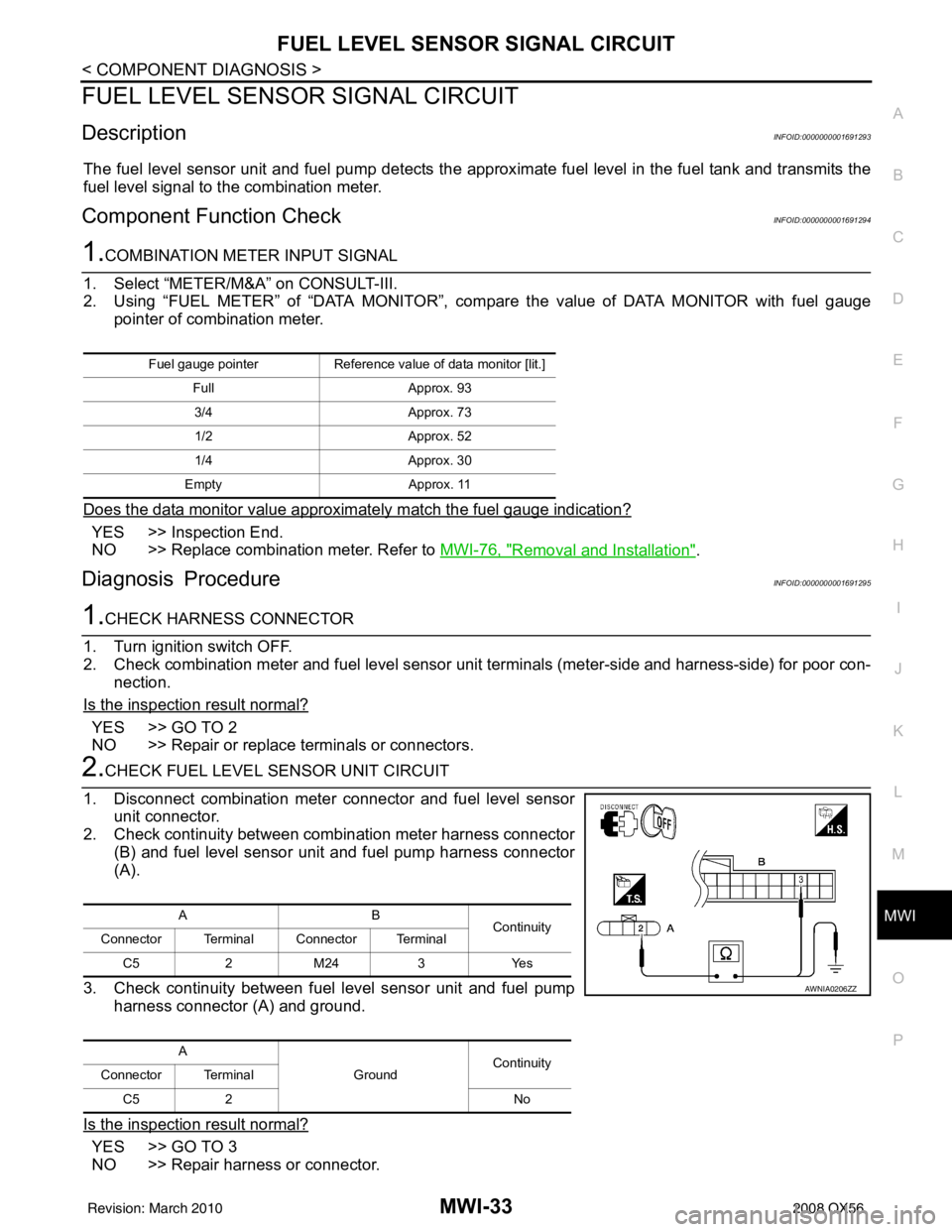
2. Check continuity between combination meter harness connector
(B) and fuel level sensor unit and fuel pump harness connector
(A).
3. Check continuity between fuel level sensor unit and fuel pump harness connector (A) and ground.
Is the inspection result normal?
YES >> GO TO 3
NO >> Repair harness or connector.
Fuel gauge pointer Reference value of data monitor [lit.]
Full Approx. 93
3/4 Approx. 73
1/2 Approx. 52
1/4 Approx. 30
Empty Approx. 11
AB
Continuity
Connector Terminal Connector Terminal
C5 2 M24 3 Yes
A GroundContinuity
Connector Terminal
C5 2 No
AWNIA0206ZZ
Revision: March 2010 2008 QX56
Page 2679 of 4083
MWI-34
< COMPONENT DIAGNOSIS >
FUEL LEVEL SENSOR SIGNAL CIRCUIT
3.CHECK FUEL LEVEL SENSOR UNIT GROUND CIRCUIT
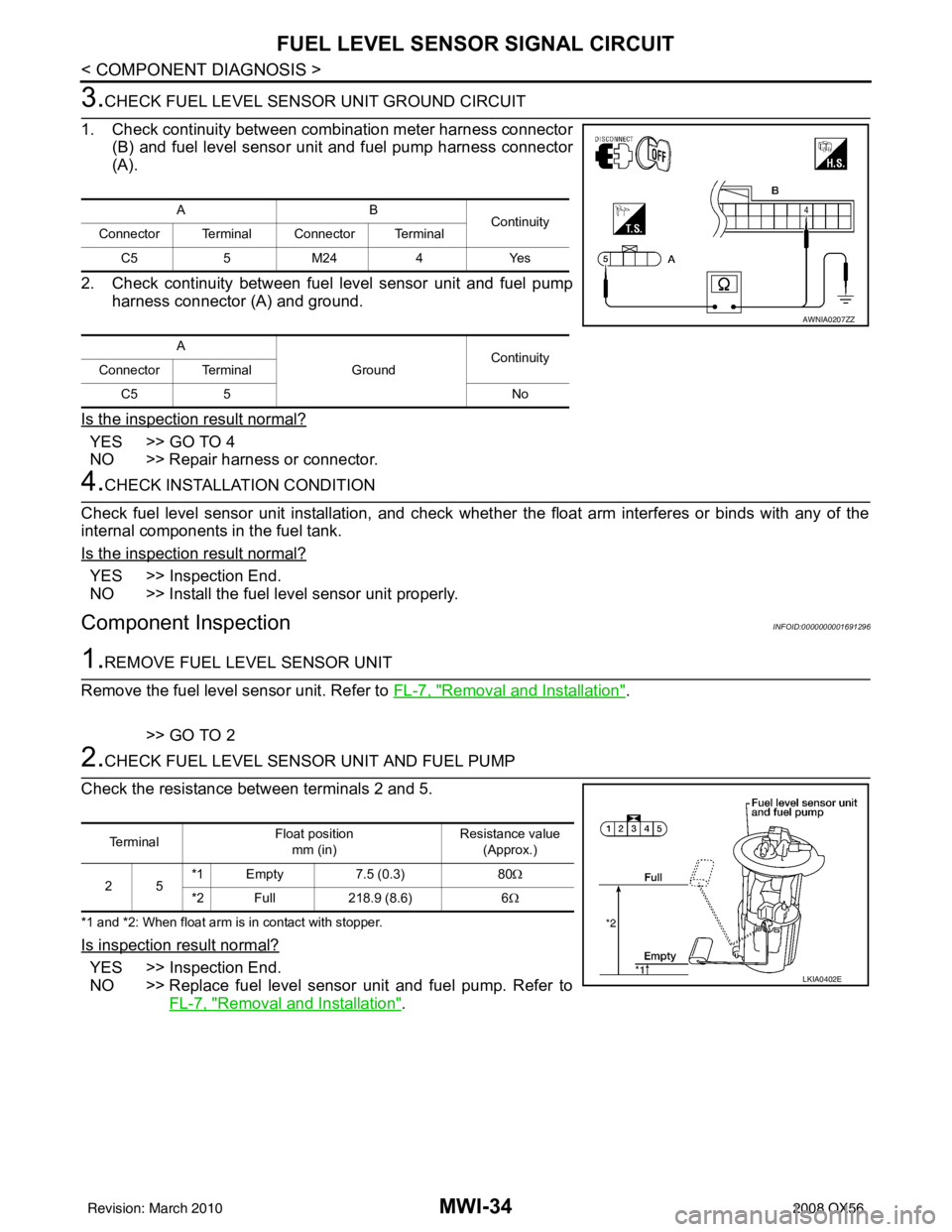
1. Check continuity between combination meter harness connector (B) and fuel level sensor uni t and fuel pump harness connector
(A).
2. Check continuity between fuel level sensor unit and fuel pump harness connector (A) and ground.
Is the inspection result normal?
YES >> GO TO 4
NO >> Repair harness or connector.
4.CHECK INSTALLATION CONDITION
Check fuel level sensor unit installation, and check whether the float arm interferes or binds with any of the
internal components in the fuel tank.
Is the inspection result normal?
YES >> Inspection End.
NO >> Install the fuel level sensor unit properly.
Component InspectionINFOID:0000000001691296
1.REMOVE FUEL LEVEL SENSOR UNIT
Remove the fuel level sensor unit. Refer to FL-7, "
Removal and Installation".
>> GO TO 2
2.CHECK FUEL LEVEL SENSOR UNIT AND FUEL PUMP
Check the resistance between terminals 2 and 5.
*1 and *2: When float arm is in contact with stopper.
Is inspection result normal?
YES >> Inspection End.
NO >> Replace fuel level sensor unit and fuel pump. Refer to FL-7, "
Removal and Installation".
AB Continuity
Connector Terminal Connector Terminal
C5 5 M24 4 Yes
A GroundContinuity
Connector Terminal
C5 5 No
AWNIA0207ZZ
Te r m i n a l Float position
mm (in) Resistance value
(Approx.)
25 *1 Empty
7.5 (0.3)80Ω
*2 Full 218.9 (8.6)6Ω
LKIA0402E
Revision: March 2010 2008 QX56
Page 2687 of 4083
MWI-42
< ECU DIAGNOSIS >
COMBINATION METER
ECU DIAGNOSIS
COMBINATION METER
Reference ValueINFOID:0000000001691309
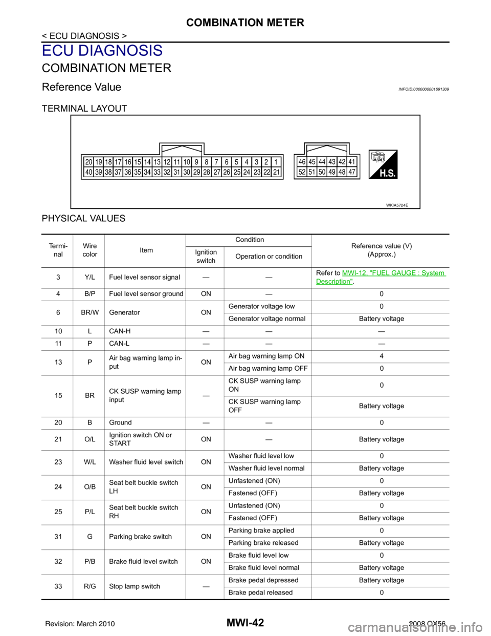
TERMINAL LAYOUT
PHYSICAL VALUES
WKIA5724E
Te r m i -nal Wire
color Item Condition
Reference value (V)
(Approx.)
Ignition
switch Operation or condition
3 Y/L Fuel level sensor signal — —Refer to MWI-12, "
FUEL GAUGE : System
Description".
4 B/P Fuel level sensor ground ON —0
6 BR/W Generator ONGenerator voltage low
0
Generator voltage normal Battery voltage
10 L CAN-H —— —
11 P C A N - L —— —
13 P Air bag warning lamp in-
put ONAir bag warning lamp ON
4
Air bag warning lamp OFF 0
15 BR CK SUSP warning lamp
input —CK SUSP warning lamp
ON
0
CK SUSP warning lamp
OFF Battery voltage
20 B Ground —— 0
21 O/L Ignition switch ON or
START ON
— Battery voltage
23 W/L Washer fluid level switch ON Washer fluid level low
0
Washer fluid level normal Battery voltage
24 O/B Seat belt buckle switch
LH ONUnfastened (ON)
0
Fastened (OFF) Battery voltage
25 P/L Seat belt buckle switch
RH ONUnfastened (ON)
0
Fastened (OFF) Battery voltage
31 G Parking brake switch ON Parking brake applied
0
Parking brake released Battery voltage
32 P/B Brake fluid level switch ON Brake fluid level low
0
Brake fluid level normal Battery voltage
33 R/G Stop lamp switch —Brake pedal depressed
Battery voltage
Brake pedal released 0
Revision: March 2010 2008 QX56
Page 2707 of 4083

MWI-62
< ECU DIAGNOSIS >
COMBINATION METER
DTC Index
INFOID:0000000001691312
Function Specifications
Speedometer
Zero indication.
Tachometer
Fuel gauge
Engine coolant temperature gauge
Engine oil pressure gauge
Voltage gauge
A/T oil temperature gauge
Illumination control
Meter illumination Change to nighttime mode when communication is lost.
Segment LCD Odometer
Freeze current indication.
A/T position Display turns off.
Buzzer Buzzer turns off.
Warning lamp/indicator lamp ABS warning lamp
Lamp turns on when communication is lost.
Brake warning lamp
VDC OFF indicator lamp
SLIP indicator lamp
A/T CHECK warning lamp
Lamp turns off when communication is lost.
Oil pressure/coolant temperature
warning lamp
Light indicator
Malfunction indicator lamp
Master warning lamp
Air bag warning lamp
High beam indicator
Turn signal indicator lamp
CRUISE indicator lamp
Driver and passenger seat belt warn-
ing lamp
Lamp turns off when disconnected.
Charge warning lamp
Security indicator lamp
4WD indicator lamp
AT P i n d i c a t o r l a m p
CK SUSP warning lamp
Low tire pressure warning lamp
Lamp will flash every second for 1 minute and then stay on con-
tinuously thereafter.
CONSULT-III display
MalfunctionReference
page
CAN COMM CIRC
[U1000] Malfunction is detected in CAN communication.
CAUTION:
Even when there is no malfunction on CAN communication system, malfunction may be
misinterpreted when battery has low voltage (when maintaining 7 - 8 V for about 2 sec-
onds) or 10A fuse [No. 19, located in
the fuse block (J/B)] is disconnected. MWI-28
VEHICLE SPEED
CIRC
[B2205]Malfunction is detected when an erroneous speed signal is input.
CAUTION:
Even when there is no malfunction on speed signal system, malfunction may be misin-
terpreted when battery has lo
w voltage (when maintaining 7 - 8 V for about 2 seconds). MWI-29
Revision: March 2010
2008 QX56
Page 2711 of 4083
MWI-66
< SYMPTOM DIAGNOSIS >
THE FUEL GAUGE POINTER DOES NOT MOVE
SYMPTOM DIAGNOSIS
THE FUEL GAUGE POINTER DOES NOT MOVE
DescriptionINFOID:0000000001691325
Fuel gauge needle will not move from a certain position.
Diagnosis ProcedureINFOID:0000000001691326
1.CHECK COMBINATION METER INPUT SIGNAL
1. Select “METER/M&A” on CONSULT-III.
2. Using “FUEL METER” of “DATA MONITOR”, comp are the monitor value with the fuel gauge reading on
the combination meter. Refer to MWI-33, "
Component Function Check".
Does monitor value match fuel gauge reading?
YES >> GO TO 2
NO >> Replace combination meter. Refer to MWI-76, "
Removal and Installation".
2.CHECK FUEL LEVEL SENSOR SIGNAL CIRCUIT
Check the fuel level sensor signal circuit. Refer to MWI-33, "
DiagnosisProcedure".
Is the inspection result normal?
YES >> GO TO 3
NO >> Repair harness or connector.
3.CHECK FUEL LEVEL SENSOR UNIT
Perform a unit check for the fuel level sensor unit. Refer to MWI-34, "
Component Inspection".
Is the inspection result normal?
YES >> GO TO 4
NO >> Replace fuel level sensor unit. Refer to FL-7, "
Removal and Installation".
4.CHECK FLOAT INTERFERENCE
Check that the float arm does not interfere or bi nd with any of the components in the fuel tank.
Is the inspection result normal?
YES >> Replace combination meter. Refer to MWI-76, "Removal and Installation".
NO >> Repair or replace malfunctioning parts.
Revision: March 2010 2008 QX56
Page 2712 of 4083
MWI
THE FUEL GAUGE POINTER DOES NOT MOVE TO "F" WHEN REFUELING
MWI-67
< SYMPTOM DIAGNOSIS >
C
D E
F
G H
I
J
K L
M B A
O P
THE FUEL GAUGE POINTER DOES NOT MOVE TO "F" WHEN REFUEL-
ING
DescriptionINFOID:0000000001691327
The fuel gauge needle will not move to “F” position when refueling.
Diagnosis ProcedureINFOID:0000000001691328
1.OBSERVE FUEL GAUGE
Does it take a long time for the pointer to move to FULL position?
YES or NO
YES >> GO TO 2
NO >> GO TO 3
2.IDENTIFY FUELING CONDITION
Was the vehicle fueled with the ignition switch ON?
YES or NO
YES >> Be sure to fuel the vehicle with the ignition swit ch OFF. Otherwise, it will take a long time to move
to FULL position because of the c haracteristic of the fuel gauge.
NO >> GO TO 3
3.OBSERVE VEHICLE POSITION
Is the vehicle parked on an incline?
YES or NO
YES >> Check the fuel level indicati on with vehicle on a level surface.
NO >> GO TO 4
4.OBSERVE FUEL GAUGE POINTER
During driving, does the fuel gauge pointer move gradually toward EMPTY position?
YES or NO
YES >> Check the components. Refer to MWI-34, "Component Inspection".
NO >> The float arm may interfere or bind with any of the components in the fuel tank.
Revision: March 2010 2008 QX56
Page 2739 of 4083
![INFINITI QX56 2008 Factory Service Manual PCS-6
< FUNCTION DIAGNOSIS >[IPDM E/R]
RELAY CONTROL SYSTEM
System Description
INFOID:0000000001696481
IPDM E/R activates the internal cont rol circuit to perform the relay ON-OFF control according to INFINITI QX56 2008 Factory Service Manual PCS-6
< FUNCTION DIAGNOSIS >[IPDM E/R]
RELAY CONTROL SYSTEM
System Description
INFOID:0000000001696481
IPDM E/R activates the internal cont rol circuit to perform the relay ON-OFF control according to](/manual-img/42/57030/w960_57030-2738.png)
PCS-6
< FUNCTION DIAGNOSIS >[IPDM E/R]
RELAY CONTROL SYSTEM
System Description
INFOID:0000000001696481
IPDM E/R activates the internal cont rol circuit to perform the relay ON-OFF control according to the input sig-
nals from various sensors and the request signals received from control units via CAN communication.
CAUTION:
IPDM E/R integrated relays cannot be removed.
Control relay Input/outputTransmit unitControl partReference
page
Front fog lamp relay Front fog lamp request signal BCM (CAN) Front fog lampsEXL-15
• Headlamp high relay
• Headlamp low relay • High beam request signal
• Low beam request signal
BCM (CAN)• Headlamp high
• Headlamp lowEXL-7
EXL-7
Tail lamp relay
Position light request signal BCM (CAN) •Parking lamps
• License plate lamps
• Tail lamps
• Trailer tow relay
• Illumination systemEXL-18
• Front wiper relay
• Front wiper high relay
Front wiper request signal BCM (CAN)
Front wiper motorWW-4
Rear window defogger re-
lay Rear window defogger re-
quest signal
BCM (CAN)
Rear window defoggerWW-8
A/C relay A/C request signal •BCM (CAN)
•ECM (CAN)
A/C compressor
HAC-20
Starter relay Ignition switch START signal TCM Starter motorSTR-8
Cooling fan relay Cooling fan request signal ECM (CAN) Cooling fan relayEC-36
Heated mirror relay Heate d mirror request signal BCM (CAN) Door mirrors DEF-4
ECM relayECM relay control signal ECM (CAN) ECM relayEC-21
Throttle control motor relay Throttle control motor control
signal ECM (CAN)
Throttle contro
l motor re-
lay EC-28
Fuel pump relay
Fuel pump request signal ECM (CAN) Fuel pumpEC-28
Ignition relay Ignition switch ON signal Ignition switch Ignition relayEC-31
Revision: March 2010 2008 QX56
Page 2755 of 4083
![INFINITI QX56 2008 Factory Service Manual PCS-22
< ECU DIAGNOSIS >[IPDM E/R]
IPDM E/R (INTELLIGENT POWER DI
STRIBUTION MODULE ENGINE ROOM)
Te r m i n a lWire
color Signal name Signal
input/
output Measuring condition
Reference value(Approx.) INFINITI QX56 2008 Factory Service Manual PCS-22
< ECU DIAGNOSIS >[IPDM E/R]
IPDM E/R (INTELLIGENT POWER DI
STRIBUTION MODULE ENGINE ROOM)
Te r m i n a lWire
color Signal name Signal
input/
output Measuring condition
Reference value(Approx.)](/manual-img/42/57030/w960_57030-2754.png)
PCS-22
< ECU DIAGNOSIS >[IPDM E/R]
IPDM E/R (INTELLIGENT POWER DI
STRIBUTION MODULE ENGINE ROOM)
Te r m i n a lWire
color Signal name Signal
input/
output Measuring condition
Reference value(Approx.)
Igni-
tion
switch Operation or condition
1 B/Y Battery power supply Input OFF —Battery voltage
2 R Battery power supply Input OFF —Battery voltage
3 BR ECM relay Output —Ignition switch ON or START
Battery voltage
Ignition switch OFF or ACC 0V
4 W/L ECM relay Output —Ignition switch ON or START
Battery voltage
Ignition switch OFF or ACC 0V
6L Throttle control motor
relay Output —Ignition switch ON or START
Battery voltage
Ignition switch OFF or ACC 0V
7 W/B ECM relay control Input — Ignition switch ON or START
0V
Ignition switch OFF or ACC Battery voltage
8 R/B Fuse 54 Output —Ignition switch ON or START
Battery voltage
Ignition switch OFF or ACC 0V
10 G Fuse 45 Output ONDaytime light system active
0V
Daytime light system inactive Battery voltage
11 Y/B A/C compressor Output ON or
START A/C switch ON or defrost A/C
switch
Battery voltage
A/C switch OFF or defrost A/C
switch 0V
12 L/W Ignition switch sup-
plied power Input —OFF or ACC
0V
ON or START Battery voltage
13 B/Y Fuel pump relay Output — Ignition switch ON or START
Battery voltage
Ignition switch OFF or ACC 0V
14 Y/R Fuse 49 Output —Ignition switch ON or START
Battery voltage
Ignition switch OFF or ACC 0V
15 LG/B Fuse 50 (VDC) Output — Ignition switch ON or START
Battery voltage
Ignition switch OFF or ACC 0V
15 GR Fuse 50 (ABS) Output — Ignition switch ON or START
Battery voltage
Ignition switch OFF or ACC 0V
16 G Fuse 51 Output —Ignition switch ON or START
Battery voltage
Ignition switch OFF or ACC 0V
17 W Fuse 55 Output —Ignition switch ON or START
Battery voltage
Ignition switch OFF or ACC 0V
19 W/R Starter motor Output START—Battery voltage
21 BR Ignition switch sup-
plied power
Input —OFF or ACC
0V
START Battery voltage
22 G Battery power supply Output OFF —Battery voltage
23 GR/W Door mirror defogger
output signal Output —When rear defogger switch is
ON
Battery voltage
When raker defogger switch is
OFF 0V
Revision: March 2010
2008 QX56