2008 INFINITI QX56 Fuel
[x] Cancel search: FuelPage 2607 of 4083

PERIODIC MAINTENANCEMA-9
< ON-VEHICLE MAINTENANCE >
C
DE
F
G H
I
J
K L
M B
MA
N
O A
(1) After 60,000 miles (96,000 km) or 48 months, inspect every 15,000 miles (24,000 km) or 12 months. Replace drive belts if da
maged.
(2) If operating mainly in dusty conditions, more frequent maintenance may be required.
(3) Maintenance-free item. For service procedures, go to the FL section.
(4) After 60,000 miles (96,000 km) or 48 months, replace every 30,000 miles (48,000 km) or 24 months.
(5) If valve noise increases, inspect valve clearance.
* Maintenance items and inte rvals with “*” are recommended by NISSAN for reliable vehicle operation. The owner need not perform
such maintenance in order to maintain the emission warranty or manufacturer recall liability. Other maintenance items and inter vals are
required.
CHASSIS AND BODY MAINTENANCE
Abbreviations: R = Replace. I = Inspect. Correct or replace if necessary. L = Lubricate. [ ]: At the mileage intervals only.
MAINTENANCE OPERATION MAINTENANCE INTERVAL
Reference
Section -
Page or -
Content Title
Perform at number of miles, kilo-
meters or months, whichever
comes first. Miles x 1,000
(km x 1,000) Months 33.75
(54)27 37.5
(60) 30 41.25
(66)33 45
(72) 36 48.75
(78)39 52.5
(84) 42 56.25
(90)45 60
(96) 48
Drive belts NOTE (1) I*MA-14
Air cleaner filter NOTE (2) [R]MA-17
EVAP vapor lines I*MA-21
Fuel lines I*MA-17
Fuel filter NOTE (3) —
Engine coolant NOTE (4) R*MA-14
Engine oil R R R R R R R R MA-18
Engine oil filterR R R R R R R R MA-18
Spark plugs (double PLATINUM-
TIPPED type)Replace every 105,000 miles (169,000 km).
MA-20
Intake and exhaust valve clear-
ance*NOTE (5)
EM-108
MAINTENANCE OPERATIONMAINTENANCE INTERVAL
Reference
Section- Page
or
- Content Title
Perform at number of miles, kilometers or
months, whichever comes first. Miles x
1,000(km x
1,000)
Months 3.75
(6)3 7.5
(12) 6 11 . 2 5
(18) 9 15
(24) 12 18.75
(30)15 22.5
(36) 18 26.25
(42)21 30
(48) 24
Brake lines and cables IIMA-30
Brake pads and rotors II I IMA-30
Automatic transmission fluid NOTE (1)IIMA-23
Transfer fluid and front final drive oil NOTE (1)IIMA-26,
MA-26
Rear final drive oil NOTE (1)IIMA-26
Steering gear and linkage, axle and suspension
parts II I I
MA-30,
MA-31
Tire Rotation NOTE (2) MA-29
Drive shaft boots and propeller shaft (4WD)II I IMA-26
Exhaust system II I IMA-23
In-cabin microfilter RRMA-22
Revision: March 2010 2008 QX56
Page 2608 of 4083
MA-10
< ON-VEHICLE MAINTENANCE >
PERIODIC MAINTENANCE
(1) If towing a trailer, or using a car-top carrier, or driving on rough or muddy roads, change (not just inspect) oil at every 30,000 miles
(48,000 km) or 24 months.
(2) Refer to “Tire rotation” unde r the “General maintenance” heading earlier in this section.
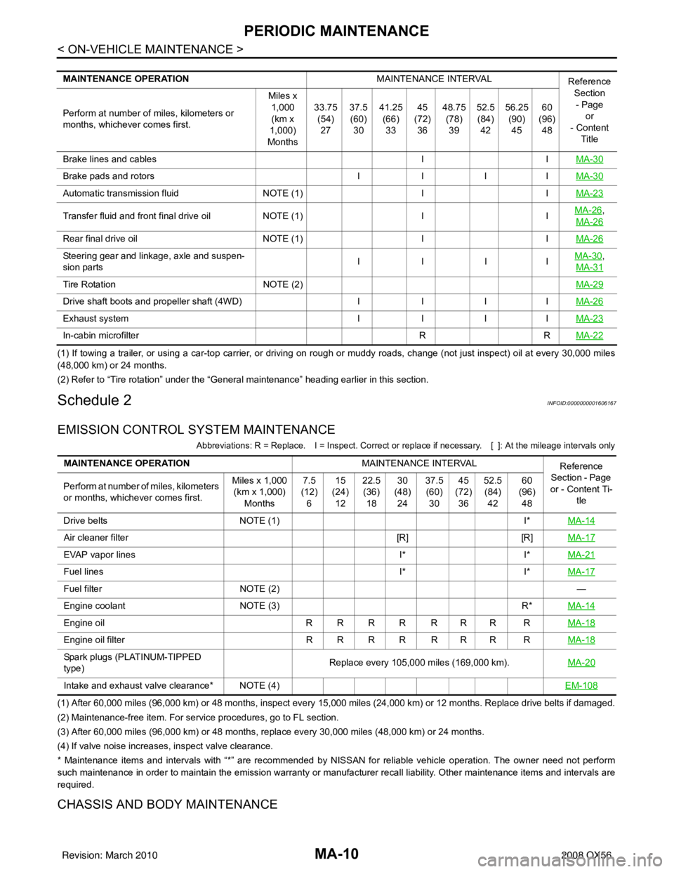
Schedule 2INFOID:0000000001606167
EMISSION CONTROL SYSTEM MAINTENANCE
Abbreviations: R = Replace. I = Inspect. Correct or r eplace if necessary. [ ]: At the mileage intervals only
(1) After 60,000 miles (96,000 km) or 48 months, inspect every 15,000 miles (24,000 km) or 12 months. Replace drive belts if damaged.
(2) Maintenance-free item. For service procedures, go to FL section.
(3) After 60,000 miles (96,000 km) or 48 months, replace every 30,000 miles (48,000 km) or 24 months.
(4) If valve noise increases, inspect valve clearance.
* Maintenance items and intervals with “*” are recommended by NISSAN for reliable vehicle operation. The owner need not perform
such maintenance in order to maintain the emission warranty or manufacturer recall liability. Other maintenance items and inter vals are
required.
CHASSIS AND BODY MAINTENANCE
MAINTENANCE OPERATION MAINTENANCE INTERVAL
Reference
Section
- Page or
- Content
Title
Perform at number of miles, kilometers or
months, whichever comes first. Miles x
1,000(km x
1,000)
Months 33.75
(54)
27 37.5
(60)
30 41.25
(66)
33 45
(72)
36 48.75
(78)
39 52.5
(84)
42 56.25
(90)
45 60
(96)
48
Brake lines and cables IIMA-30
Brake pads and rotors IIIIMA-30
Automatic transmission fluid NOTE (1)IIMA-23
Transfer fluid and front final drive oil NOTE (1)IIMA-26,
MA-26
Rear final drive oil NOTE (1)IIMA-26
Steering gear and linkage, axle and suspen-
sion parts IIIIMA-30,
MA-31
Tire Rotation NOTE (2) MA-29
Drive shaft boots and propeller shaft (4WD)IIIIMA-26
Exhaust system IIIIMA-23
In-cabin microfilter RRMA-22
MAINTENANCE OPERATION MAINTENANCE INTERVAL
Reference
Section - Page
or - Content Ti- tle
Perform at number of miles, kilometers
or months, whichever comes first. Miles x 1,000
(km x 1,000)
Months 7.5
(12)
6 15
(24)
12 22.5
(36)
18 30
(48)
24 37.5
(60)
30 45
(72)
36 52.5
(84)
42 60
(96)
48
Drive belts NOTE (1) I*MA-14
Air cleaner filter [R][R]MA-17
EVAP vapor lines I*I*MA-21
Fuel lines I*I*MA-17
Fuel filter NOTE (2) —
Engine coolant NOTE (3) R*MA-14
Engine oil R R R R R R R R MA-18
Engine oil filterR R R R R R R R MA-18
Spark plugs (PLATINUM-TIPPED
type) Replace every 105,000 miles (169,000 km).
MA-20
Intake and exhaust valve clearance* NOTE (4) EM-108
Revision: March 20102008 QX56
Page 2610 of 4083
MA-12
< ON-VEHICLE MAINTENANCE >
RECOMMENDED FLUIDS AND LUBRICANTS
RECOMMENDED FLUIDS AND LUBRICANTS
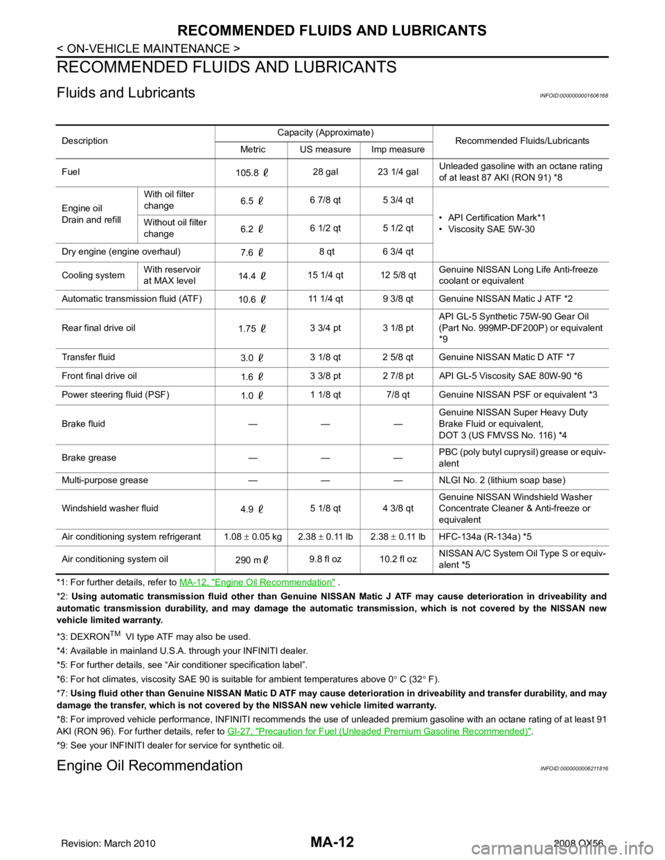
Fluids and LubricantsINFOID:0000000001606168
*1: For further details, refer to MA-12, "Engine Oil Recommendation" .
*2: Using automatic transmission fluid other than Genuine NISSAN Matic J ATF may cause deterioration in driveability and
automatic transmission durability, and may damage the automatic transmission, which is not covered by the NISSAN new
vehicle limited warranty.
*3: DEXRON
TM VI type ATF may also be used.
*4: Available in mainland U.S.A. through your INFINITI dealer.
*5: For further details, see “Air conditioner specification label”.
*6: For hot climates, viscosity SAE 90 is suitable for ambient te mperatures above 0° C (32 ° F).
*7: Using fluid other than Genuine NISSAN Matic D ATF may cause de terioration in driveability and transfer durability, and may
damage the transfer, which is not covered by the NISSAN new vehicle limited warranty.
*8: For improved vehicle performance, INFINITI recommends the use of unleaded premium gasoline with an octane rating of at leas t 91
AKI (RON 96). For further details, refer to GI-27, "
Precaution for Fuel (Unleaded Premium Gasoline Recommended)".
*9: See your INFINITI dealer for service for synthetic oil.
Engine Oil RecommendationINFOID:0000000006211816
Description Capacity (Approximate)
Recommended Fluids/Lubricants
Metric US measure Imp measure
Fuel 105.8 28 gal 23 1/4 gal Unleaded gasoline with an octane rating
of at least 87 AKI (RON 91) *8
Engine oil
Drain and refill With oil filter
change
6.5
6 7/8 qt 5 3/4 qt
• API Certification Mark*1
• Viscosity SAE 5W-30
Without oil filter
change
6.2
6 1/2 qt 5 1/2 qt
Dry engine (engine overhaul) 7.6 8 qt
6 3/4 qt
Cooling system With reservoir
at MAX level
14.4
15 1/4 qt 12 5/8 qt Genuine NISSAN Long Life Anti-freeze
coolant or equivalent
Automatic transmission fluid (ATF) 10.6 11 1/4 qt 9 3/8 qt Genuine NISSAN Matic J ATF *2
Rear final drive oil 1.75 3 3/4 pt 3 1/8 pt API GL-5 Synthetic 75W-90 Gear Oil
(Part No. 999MP-DF200P) or equivalent
*9
Transfer fluid 3.0 3 1/8 qt 2 5/8 qt Genuine NISSAN Matic D ATF *7
Front final drive oil 1.6 3 3/8 pt 2 7/8 pt API GL-5 Viscosity SAE 80W-90 *6
Power steering fluid (PSF) 1.0 1 1/8 qt 7/8 qt Genuine NISSAN PSF or equivalent *3
Brake fluid —— —Genuine NISSAN Super Heavy Duty
Brake Fluid or equivalent,
DOT 3 (US FMVSS No. 116) *4
Brake grease —— —PBC (poly butyl cuprysil) grease or equiv-
alent
Multi-purpose grease —— — NLGI No. 2 (lithium soap base)
Windshield washer fluid 4.9 5 1/8 qt 4 3/8 qt Genuine NISSAN Windshield Washer
Concentrate Cleaner & Anti-freeze or
equivalent
Air conditioning system refrigerant 1.08 ± 0.05 kg 2.38 ± 0.11 lb 2.38 ± 0.11 lb HFC-134a (R-134a) *5
Air conditioning system oil 290 m9.8 fl oz 10.2 fl oz NISSAN A/C System Oil Type S or equiv-
alent *5
Revision: March 2010
2008 QX56
Page 2611 of 4083

RECOMMENDED FLUIDS AND LUBRICANTSMA-13
< ON-VEHICLE MAINTENANCE >
C
DE
F
G H
I
J
K L
M B
MA
N
O A
NISSAN recommends the use of an energy conserving oil in order to
improve fuel economy. Select only
engine oils that meet the Ameri-
can Petroleum Institute (API) cert ification and International Lubricant
Standardization and Approval Committee (ILSAC) certification and
SAE viscosity standard (2). These oils have the API certification
mark (1) on the front of the container. Oils which do not have the
specified quality label should not be used as they could cause
engine damage.
Anti-Freeze Coolant Mixture RatioINFOID:0000000006211817
The engine cooling system is filled at the factory with a high-quality, year-round, anti-freeze coolant solution.
The anti-freeze solution contains rust and corrosion inhi bitors. Therefore, additional cooling system additives
are not necessary.
CAUTION:
• When adding or replacing coolant, be sure to use only Genuine NISSAN Long Life Anti-freeze cool-
ant or equivalent with the proper mixture ratio of 50% anti-freeze and 50% demineralized water or
distilled water.
• Other types of coolant solutions may damage your cooling system.
ALPIA0001ZZ
For outside temperatures down to: Anti-freeze coolant mixture ratio
° C ° F Genuine NISSAN Long Life An-
tifreeze coolant Demineralized water or distilled wa-
ter
– 35° – 30° 50 % 50 %
Revision: March 2010 2008 QX56
Page 2615 of 4083
ENGINE MAINTENANCEMA-17
< ON-VEHICLE MAINTENANCE >
C
DE
F
G H
I
J
K L
M B
MA
N
O A
2. Fill the radiator and the reservoir tank (to the “MAX”
line), with water. Reinstall the radiator cap and leave
the vented reservoir cap off.
3. Run the engine until it reaches normal operating temperature.
4. Press the engine accelerator two or three times under no-load.
5. Stop the engine and wait until it cools down.
6. Drain the water from the engine cooling system. Refer to CO-11, "
Changing Engine Coolant" .
7. Repeat steps 2 through 6 until clear water begins to drain from the radiator.
Checking Fuel LineINFOID:0000000001606172
Inspect the fuel lines and fuel tank for improper mounting, leaks,
cracks, damage, loose connections, chafing, or deterioration.
As necessary, repair or replace any faulty parts.
Changing Fuel FilterINFOID:0000000001606173
The fuel filter is part of the fuel level sensor unit, fuel filter and fuel pump assembly. Refer to FL-7, "Removal
and Installation" .
WARNING:
Before replacing the fuel filter, release the fuel pressure from the fuel system. Refer to EC-494, "
Fuel
Pressure Check".
Changing Engine Air Cleaner FilterINFOID:0000000001606174
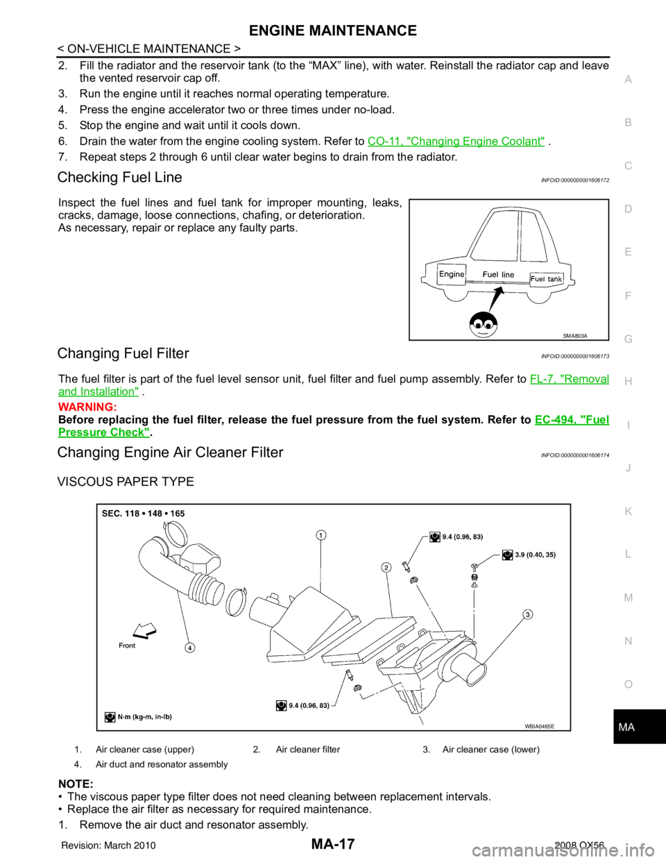
VISCOUS PAPER TYPE
NOTE:
• The viscous paper type filter does not need cleaning between replacement intervals.
• Replace the air filter as necessary for required maintenance.
1. Remove the air duct and resonator assembly.
SMA803A
1. Air cleaner case (upper) 2. Air cleaner filter3. Air cleaner case (lower)
4. Air duct and resonator assembly
WBIA0465E
Revision: March 2010 2008 QX56
Page 2619 of 4083
ENGINE MAINTENANCEMA-21
< ON-VEHICLE MAINTENANCE >
C
DE
F
G H
I
J
K L
M B
MA
N
O A
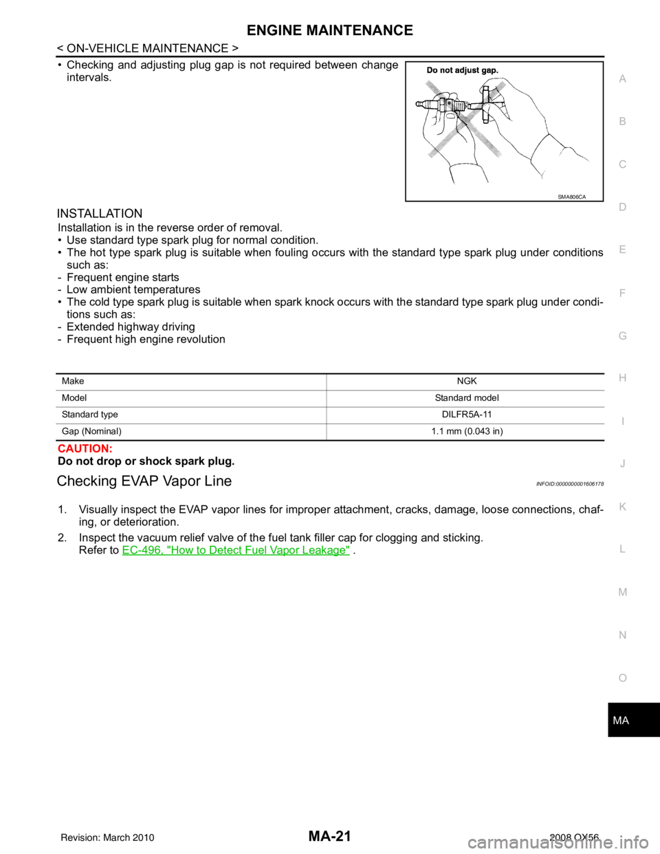
• Checking and adjusting plug gap is not required between change
intervals.
INSTALLATION
Installation is in the reverse order of removal.
• Use standard type spark plug for normal condition.
• The hot type spark plug is suitable when fouling occurs with the standard type spark plug under conditionssuch as:
- Frequent engine starts
- Low ambient temperatures
• The cold type spark plug is suitable when spark knock occurs with the standard type spark plug under condi- tions such as:
- Extended highway driving
- Frequent high engine revolution
CAUTION:
Do not drop or shock spark plug.
Checking EVAP Vapor LineINFOID:0000000001606178
1. Visually inspect the EVAP vapor lines for improper attachment, cracks, damage, loose connections, chaf-
ing, or deterioration.
2. Inspect the vacuum relief valve of the fuel tank filler cap for clogging and sticking.
Refer to EC-496, "
How to Detect Fuel Vapor Leakage" .
SMA806CA
Make NGK
Model Standard model
Standard type DILFR5A-11
Gap (Nominal) 1.1 mm (0.043 in)
Revision: March 2010 2008 QX56
Page 2646 of 4083
MWI
MWI-1
DRIVER INFORMATION & MULTIMEDIA
C
DE
F
G H
I
J
K L
M B
SECTION MWI
A
O P
CONTENTS
METER, WARNING LAMP & INDICATOR
BASIC INSPECTION ....... .............................4
DIAGNOSIS AND REPAIR WORKFLOW ..... .....4
Work Flow ........................................................... ......4
FUNCTION DIAGNOSIS ...............................5
METER SYSTEM ............................................ .....5
METER SYSTEM .........................................................5
METER SYSTEM : System Diagram ........................5
METER SYSTEM : System Description ....................5
METER SYSTEM : Arrangem ent of Combination
Meter ................................................................... ......
6
METER SYSTEM : Component Parts Location ........7
METER SYSTEM : Component Description ....... ......7
SPEEDOMETER ..........................................................8
SPEEDOMETER : System Diagram ................... ......8
SPEEDOMETER : System Description .....................8
SPEEDOMETER : Component Parts Location .........9
SPEEDOMETER : Component Description ........ ......9
TACHOMETER ...................................................... ......9
TACHOMETER : System Diagram ...........................9
TACHOMETER : System De scription .....................10
TACHOMETER : Component Parts Location ..... ....10
TACHOMETER : Component Description ..............10
ENGINE COOLANT TEMPERATURE GAUGE .... ....10
ENGINE COOLANT TEMPERATURE GAUGE :
System Diagram ......................................................
11
ENGINE COOLANT TEMPERATURE GAUGE :
System Description .................................................
11
ENGINE COOLANT TEMPERATURE GAUGE :
Component Parts Location ......................................
11
ENGINE COOLANT TEMPERATURE GAUGE :
Component Description ...........................................
12
FUEL GAUGE ........................................................ ....12
FUEL GAUGE : System Diagram ...........................12
FUEL GAUGE : System Description .......................12
FUEL GAUGE : Component Parts Location ...........12
FUEL GAUGE : Component Description ............. ....13
ENGINE OIL PRESSURE GAUGE ............................13
ENGINE OIL PRESSURE GAUGE : System Dia-
gram .................................................................... ....
13
ENGINE OIL PRESSURE GAUGE : System De-
scription ...................................................................
13
ENGINE OIL PRESSURE GAUGE : Component
Parts Location ..........................................................
14
ENGINE OIL PRESSURE GAUGE : Component
Description ...............................................................
14
VOLTAGE GAUGE ................................................ ....14
VOLTAGE GAUGE : System Diagram ....................15
VOLTAGE GAUGE : System Description ................15
VOLTAGE GAUGE : Component Parts Location ....15
VOLTAGE GAUGE : Component Description .........16
ODO/TRIP METER ................................................. ....16
ODO/TRIP METER : System Diagram ....................16
ODO/TRIP METER : System Description ................16
ODO/TRIP METER : Component Parts Location ....16
ODO/TRIP METER : Component Description .........17
SHIFT POSITION INDICATOR .............................. ....17
SHIFT POSITION INDICATOR : System Diagram ....17
SHIFT POSITION INDICATOR : System Descrip-
tion ...........................................................................
17
SHIFT POSITION INDICATOR : Component
Parts Location ..........................................................
18
SHIFT POSITION INDICATOR : Component De-
scription ............................................................... ....
18
WARNING LAMPS/INDICATOR LAMPS .............. ....18
WARNING LAMPS/INDICATOR LAMPS : System
Diagram ............................................................... ....
18
WARNING LAMPS/INDICATOR LAMPS : System
Description ........................................................... ....
19
WARNING LAMPS/INDICATOR LAMPS : Com-
ponent Parts Location ..............................................
19
WARNING LAMPS/INDICATOR LAMPS : Com-
ponent Description ...................................................
19
Revision: March 2010 2008 QX56
Page 2647 of 4083

MWI-2
INFORMATION DISPLAY .........................................19
INFORMATION DISPLAY : System Diagram .........20
INFORMATION DISPLAY : System Description ....20
INFORMATION DISPLAY : Component Parts Lo-
cation ................................................................... ...
21
INFORMATION DISPLAY : Component Descrip-
tion ....................................................................... ...
21
COMPASS .........................................................22
Description ........................................................... ...22
DIAGNOSIS SYSTEM (METER) .......................24
Diagnosis Description .......................................... ...24
CONSULT-III Function (METER/M&A) ................ ...25
COMPONENT DIAGNOSIS ........................28
DTC U1000 CAN COMMUNICATION ............ ...28
DTC Logic ............................................................ ...28
Diagnosis Procedure .............................................28
DTC B2205 VEHICLE SPEED CIRCUIT ...........29
Description ........................................................... ...29
DTC Logic ...............................................................29
Diagnosis Procedure .............................................29
POWER SUPPLY AND GROUND CIRCUIT .....30
COMBINATION METER ........................................ ...30
COMBINATION METER : Diagnosis Procedure ....30
BCM (BODY CONTROL MODULE) ...................... ...30
BCM (BODY CONTROL MODULE) : Diagnosis
Procedure ...............................................................
31
IPDM E/R (INTELLIGENT POWER DISTRIBU-
TION MODULE ENGINE ROOM) .......................... ...
31
IPDM E/R (INTELLIGENT POWER DISTRIBU-
TION MODULE ENGINE ROOM) : Diagnosis Pro-
cedure .....................................................................
31
FUEL LEVEL SENSOR SIGNAL CIRCUIT .......33
Description ........................................................... ...33
Component Function Check ...................................33
Diagnosis Procedure .............................................33
Component Inspection ............................................34
OIL PRESSURE SWITCH SIGNAL CIRCUIT ...35
Description ..............................................................35
Component Function Check ...................................35
Diagnosis Procedure ..............................................35
Component Inspection ............................................35
PARKING BRAKE SWITCH SIGNAL CIR-
CUIT ...................................................................
36
Description ........................................................... ...36
Component Function Check ...................................36
Diagnosis Procedure ..............................................36
Component Inspection ............................................36
WASHER LEVEL SWITCH SIGNAL CIRCUIT ...37
Description ........................................................... ...37
Diagnosis Procedure ............................................ ...37
Component Inspection ............................................37
COMPASS .........................................................38
Wiring Diagram .................................................... ...38
CLOCK ..............................................................40
Wiring Diagram .................................................... ...40
ECU DIAGNOSIS .......................................42
COMBINATION METER ................................. ...42
Reference Value .................................................. ...42
Wiring Diagram .......................................................44
Fail Safe ..................................................................61
DTC Index ...............................................................62
BCM (BODY CONTROL MODULE) ..................64
Reference Value .................................................. ...64
Terminal Layout ......................................................64
Physical Values .......................................................64
Wiring Diagram .......................................................64
DTC Inspection Priority Chart ...............................64
DTC Index ..............................................................64
IPDM E/R (INTELLIGENT POWER DISTRI-
BUTION MODULE ENGINE ROOM) .................
65
Reference Value .................................................. ...65
Terminal Layout ......................................................65
Physical Values .......................................................65
Wiring Diagram .......................................................65
Fail Safe .................................................................65
DTC Index ..............................................................65
SYMPTOM DIAGNOSIS ............................66
THE FUEL GAUGE POINTER DOES NOT
MOVE .............................................................. ...
66
Description ........................................................... ...66
Diagnosis Procedure ...............................................66
THE FUEL GAUGE POINTER DOES NOT
MOVE TO "F" WHEN REFUELING ..................
67
Description ........................................................... ...67
Diagnosis Procedure ...............................................67
THE OIL PRESSURE WARNING LAMP
DOES NOT TURN ON .................................... ...
68
Description ........................................................... ...68
Diagnosis Procedure ...............................................68
THE OIL PRESSURE WARNING LAMP
DOES NOT TURN OFF .................................. ...
69
Description ........................................................... ...69
Diagnosis Procedure ...............................................69
THE PARKING BRAKE RELEASE WARNING
CONTINUES DISPLAYING, OR DOES NOT
DISPLAY ............................................................
70
Description ........................................................... ...70
Diagnosis Procedure ...............................................70
Revision: March 2010 2008 QX56