2008 INFINITI QX56 Fuel
[x] Cancel search: FuelPage 2124 of 4083

ON-VEHICLE SERVICEFSU-7
< ON-VEHICLE MAINTENANCE >
C
DF
G H
I
J
K L
M A
B
FSU
N
O P
ON-VEHICLE MAINTENANCE
ON-VEHICLE SERVICE
Front Suspension PartsINFOID:0000000001534627
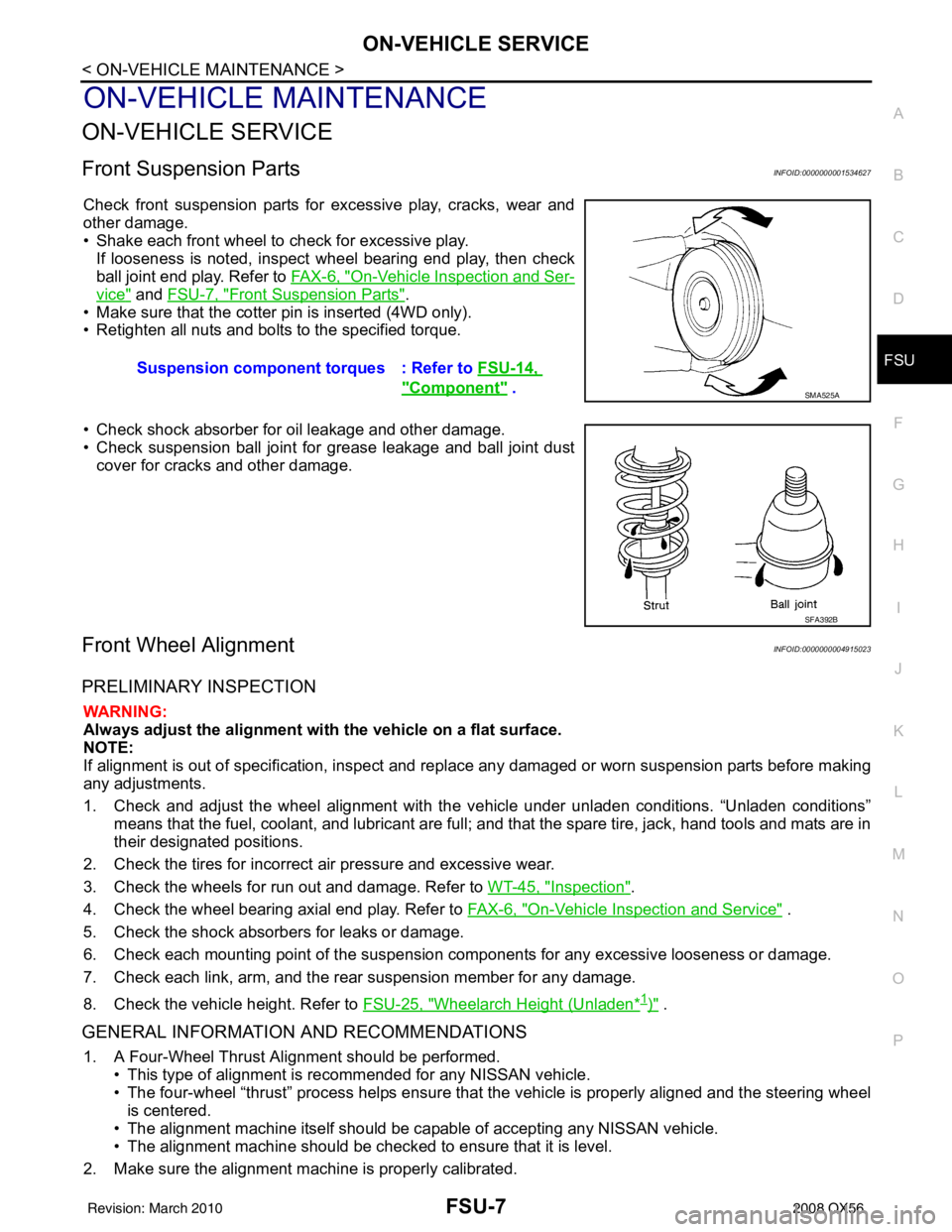
Check front suspension parts for excessive play, cracks, wear and
other damage.
• Shake each front wheel to check for excessive play. If looseness is noted, inspect wheel bearing end play, then check
ball joint end play. Refer to FA X - 6 , "
On-Vehicle Inspection and Ser-
vice" and FSU-7, "Front Suspension Parts".
• Make sure that the cotter pin is inserted (4WD only).
• Retighten all nuts and bolts to the specified torque.
• Check shock absorber for oil leakage and other damage.
• Check suspension ball joint for grease leakage and ball joint dust cover for cracks and other damage.
Front Wheel AlignmentINFOID:0000000004915023
PRELIMINARY INSPECTION
WARNING:
Always adjust the alignment with the vehicle on a flat surface.
NOTE:
If alignment is out of specificat ion, inspect and replace any damaged or worn suspension parts before making
any adjustments.
1. Check and adjust the wheel alignment with the vehicle under unladen conditions. “Unladen conditions”
means that the fuel, coolant, and lubricant are full; and that the spare tire, jack, hand tools and mats are in
their designated positions.
2. Check the tires for incorrect air pressure and excessive wear.
3. Check the wheels for run out and damage. Refer to WT-45, "
Inspection".
4. Check the wheel bearing axial end play. Refer to FAX-6, "
On-Vehicle Inspection and Service" .
5. Check the shock absorbers for leaks or damage.
6. Check each mounting point of the suspension components for any excessive looseness or damage.
7. Check each link, arm, and the rear suspension member for any damage.
8. Check the vehicle height. Refer to FSU-25, "
Wheelarch Height (Unladen*1)" .
GENERAL INFORMATION AND RECOMMENDATIONS
1. A Four-Wheel Thrust Alignment should be performed.
• This type of alignment is re commended for any NISSAN vehicle.
• The four-wheel “thrust” process helps ensure that the vehicle is properly aligned and the steering wheel
is centered.
• The alignment machine itself should be ca pable of accepting any NISSAN vehicle.
• The alignment machine should be checked to ensure that it is level.
2. Make sure the alignment machine is properly calibrated. Suspension component torques : Refer to
FSU-14,
"Component" . SMA525A
SFA392B
Revision: March 2010 2008 QX56
Page 2141 of 4083

FSU-24
< SERVICE DATA AND SPECIFICATIONS (SDS)
SERVICE DATA AND SPECIFICATIONS (SDS)
SERVICE DATA AND SPECIFICATIONS (SDS)
SERVICE DATA AND SPECIFICATIONS (SDS)
General SpecificationINFOID:0000000001534621
Spring Free HeightINFOID:0000000001534622
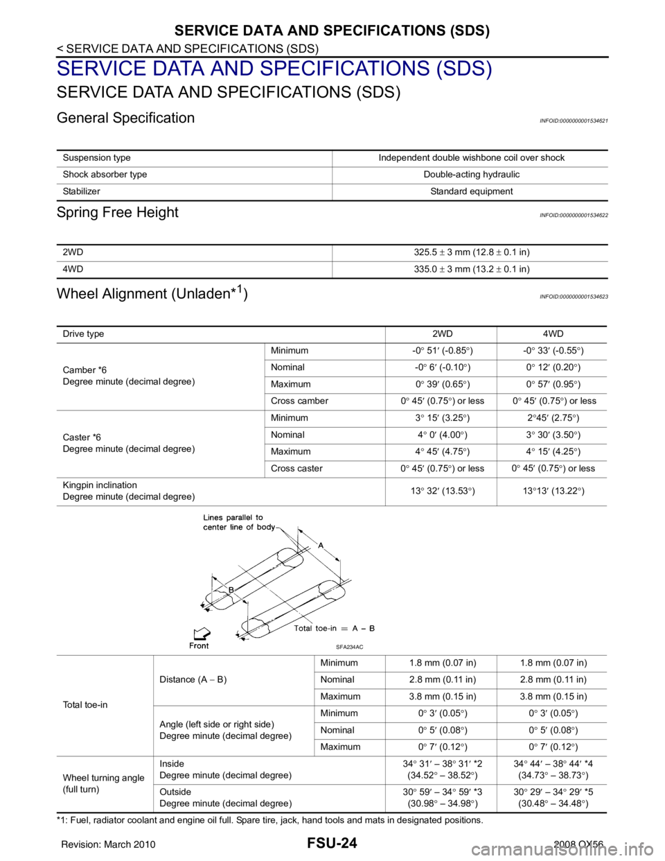
Wheel Alignment (Unladen*1)INFOID:0000000001534623
*1: Fuel, radiator coolant and engine oil full. Spare tire, jack, hand tools and mats in designated positions.Suspension type
Independent double wishbone coil over shock
Shock absorber type Double-acting hydraulic
Stabilizer Standard equipment
2WD325.5 ± 3 mm (12.8 ± 0.1 in)
4WD 335.0 ± 3 mm (13.2 ± 0.1 in)
Drive type 2WD 4WD
Camber *6
Degree minute (decimal degree) Minimum
-0° 51 ′ (-0.85 °)- 0° 33 ′ (-0.55 °)
Nominal -0° 6 ′ (-0.10 °)0 ° 12 ′ (0.20 °)
Maximum 0° 39 ′ (0.65 °)0 ° 57 ′ (0.95 °)
Cross camber 0° 45 ′ (0.75 °) or less 0 ° 45 ′ (0.75 °) or less
Caster *6
Degree minute (decimal degree) Minimum
3° 15 ′ (3.25 °)2 °45 ′ (2.75 °)
Nominal 4° 0 ′ (4.00 °)3 ° 30 ′ (3.50 °)
Maximum 4° 45 ′ (4.75 °)4 ° 15 ′ (4.25 °)
Cross caster 0° 45 ′ (0.75 °) or less 0
° 45 ′ (0.7
5°) or less
Kingpin inclination
Degree minute (decimal degree) 13
° 32 ′ (13.53 °)1 3°13 ′ (13.22 °)
To t a l t o e - i n Distance (A
− B) Minimum
1.8 mm (0.07 in) 1.8 mm (0.07 in)
Nominal 2.8 mm (0.11 in) 2.8 mm (0.11 in)
Maximum 3.8 mm (0.15 in) 3.8 mm (0.15 in)
Angle (left side or right side)
Degree minute (decimal degree) Minimum
0° 3 ′ (0.05 °)0 ° 3 ′ (0.05 °)
Nominal 0° 5 ′ (0.08 °)0 ° 5 ′ (0.08 °)
Maximum 0° 7 ′ (0.12 °)0 ° 7 ′ (0.12 °)
Wheel turning angle
(full turn) Inside
Degree minute (decimal degree)
34
° 31 ′ – 38 ° 31 ′ *2
(34.52 ° – 38.52 °) 34
° 44 ′ – 38° 44′ *4
(34.73 ° – 38.73 °)
Outs id
e
Degree minute (decimal degree) 30
° 59 ′ – 34 ° 59 ′ *3
(30.98 ° – 34.98 °) 30
° 29 ′ – 34° 29′ *5
(30.48 ° – 34.48 °)
SFA234AC
Revision: March 2010 2008 QX56
Page 2142 of 4083

SERVICE DATA AND SPECIFICATIONS (SDS)FSU-25
< SERVICE DATA AND SPECIFICATIONS (SDS)
C
DF
G H
I
J
K L
M A
B
FSU
N
O P
*2: Target value 37 ° 31 ′ (37.52 °)
*3: Target value 33 ° 59 ′ (33.98 °)
*4: Target value 37 ° 44 ′ (37.73 °)
*5: Target value 33 ° 29 ′ (33.48 °)
*6: Some vehicles may be equipped with straight (non-adjustable) lower link bolts and washers. In order to adjust camber and ca ster on
these vehicles, first replace the lower link bolts and washers with adjustable (cam) bolts and washers.
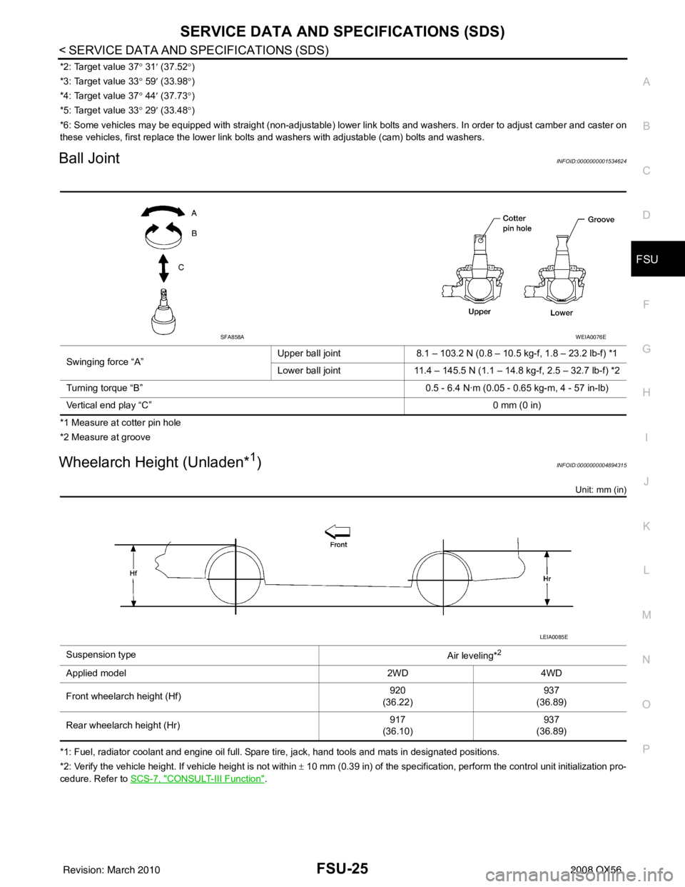
Ball JointINFOID:0000000001534624
*1 Measure at cotter pin hole
*2 Measure at groove
Wheelarch Height (Unladen*1)INFOID:0000000004894315
Unit: mm (in)
*1: Fuel, radiator coolant and engine oil full. Spare tire, jack, hand tools and mats in designated positions.
*2: Verify the vehicle height. If vehicle height is not within ± 10 mm (0.39 in) of the specification, perform the control unit initialization pro-
cedure. Refer to SCS-7, "
CONSULT-III Function".
Swinging force “A”
Upper ball joint 8.1 – 103.2 N (0.8 – 10.5 kg-f, 1.8 – 23.2 lb-f) *1
Lower ball joint 11.4 – 145.5 N (1.1 – 14.8 kg-f, 2.5 – 32.7 lb-f) *2
Turning torque “B” 0.5 - 6.4 N·m (0.05 - 0.65 kg-m, 4 - 57 in-lb)
Vertical end play “C” 0 mm (0 in)
SFA858AWEIA0076E
Suspension type
Air leveling*2
Applied model2WD4WD
Front wheelarch height (Hf) 920
(36.22) 937
(36.89)
Rear wheelarch height (Hr) 917
(36.10) 937
(36.89)
LEIA0085E
Revision: March 2010 2008 QX56
Page 2143 of 4083

GI-1
GENERAL INFORMATION
C
DE
F
G H
I
J
K L
M B
GI
SECTION GI
N
O P
CONTENTS
GENERAL INFORMATION
HOW TO USE THIS MANU AL ......................3
HOW TO USE THIS MANUAL ....................... .....3
Description .......................................................... ......3
Terms ........................................................................3
Units ..........................................................................3
Contents ....................................................................3
Relation between Illustrations and Descriptions .......4
Components ..............................................................4
HOW TO FOLLOW TROUBLE DIAGNOSES .....6
Description ................................................................6
How to Follow Test Groups in Trouble Diagnosis ......6
Key to Symbols Signifying Measurements or Pro-
cedures ............................................................... ......
7
HOW TO READ WIRING DIAGRAMS ................9
Connector symbols ............................................. ......9
Sample/wiring diagram -example- ...........................10
Description ..............................................................11
ABBREVIATIONS .......................................... ....13
Abbreviation List .................................................. ....13
TIGHTENING TORQUE OF STANDARD
BOLTS ................................................................
14
Tightening Torque Table .........................................14
RECOMMENDED CHEMICAL PRODUCTS
AND SEALANTS ............................................ ....
15
Recommended Chemical Products and Sealants ....15
TERMINOLOGY .................................................16
SAE J1930 Terminology List ............................... ....16
FEATURES OF NEW MODEL .....................20
IDENTIFICATION INFORMATION .....................20
Model Variation ................................................... ....20
Identification Number ..............................................21
Identification Plate ...................................................22
Dimensions .............................................................23
Wheels & Tires .................................................... ....23
PRECAUTION ..............................................24
PRECAUTIONS .................................................24
Description ........................................................... ....24
Precaution for Supplemental Restraint System
(SRS) "AIR BAG" and "SEAT BELT PRE-TEN-
SIONER" .................................................................
24
Precaution Necessary for Steering Wheel Rota-
tion After Battery Disconnect ...................................
24
Procedures without Cowl Top Cover .......................25
General Precautions ................................................25
Three Way Catalyst .................................................27
Precaution for Fuel (Unleaded Premium Gasoline
Recommended) .......................................................
27
Multiport Fuel Injection System or Engine Control
System .....................................................................
27
Hoses ......................................................................27
Engine Oils ..............................................................28
Air Conditioning .......................................................29
LIFTING POINT .................................................30
Pantograph Jack ......................................................30
Garage Jack and Safety Stand ................................30
2-Pole Lift ................................................................30
TOW TRUCK TOWING .....................................32
Tow Truck Towing ...................................................32
Vehicle Recovery (Freeing a stuck vehicle) ............33
BASIC INSPECTION ...................................34
SERVICE INFORMATION FOR ELECTRICAL
INCIDENT ..........................................................
34
Work Flow ............................................................ ....34
Control Units and Electrical Parts ............................34
How to Check Terminal ...........................................35
Intermittent Incident ............................................. ....38
Circuit Inspection .....................................................41
CONSULT-III CHECKING SYSTEM .................46
Revision: March 2010 2008 QX56
Page 2158 of 4083

GI-16
< HOW TO USE THIS MANUAL >
TERMINOLOGY
TERMINOLOGY
SAE J1930 Terminology ListINFOID:0000000001539196
All emission related terms used in this publication in accordance with SAE J1930 are listed. Accordingly, new
terms, new acronyms/abbreviations and old terms are listed in the following chart.
NEW TERMNEW ACRONYM /
ABBREVIATION OLD TERM
Air cleaner ACL Air cleaner
Barometric pressure BARO ***
Barometric pressure sensor-BCDD BAROS-BCDD BCDD
Camshaft position CMP ***
Camshaft position sensor CMPSCrank angle sensor
Canister *** Canister
Carburetor CARBCarburetor
Charge air cooler CACIntercooler
Closed loop CLClosed loop
Closed throttle position switch CTP switchIdle switch
Clutch pedal position switch CPP switch Clutch switch
Continuous fuel injection system CFI system***
Continuous trap oxidizer system CTOX system ***
Crankshaft position CKP***
Crankshaft position sensor CKPS***
Data link connector DLC***
Data link connector for CONSULT-III DLC for CONSULT-IIIDiagnostic connector for CONSULT-III
Diagnostic test mode DTMDiagnostic mode
Diagnostic test mode selector DTM selectorDiagnostic mode selector
Diagnostic test mode I DTM I Mode I
Diagnostic test mode II DTM IIMode II
Diagnostic trouble code DTCMalfunction code
Direct fuel injection system DFI system ***
Distributor ignition system DI system Ignition timing control
Early fuel evaporation-mixture heater EFE-mixture heater Mixture heater
Early fuel evaporation system EFE system Mixture heater control
Electrically erasable programmable read
only memory EEPROM
***
Electronic ignition system EI systemIgnition timing control
Engine control EC ***
Engine control module ECM ECCS control unit
Engine coolant temperature ECT Engine temperature
Engine coolant temperature sensor ECTS Engine temperature sensor
Engine modification EM ***
Engine speed RPM Engine speed
Erasable programmable read only memory EPROM ***
Evaporative emission canister EVAP canister Canister
Evaporative emission system EVAP system Canister control solenoid valve
Exhaust gas recirculation valve EGR valve EGR valve
Revision: March 2010 2008 QX56
Page 2159 of 4083

TERMINOLOGYGI-17
< HOW TO USE THIS MANUAL >
C
DE
F
G H
I
J
K L
M B
GI
N
O P
Exhaust gas recirculation control-BPT
valve EGRC-BPT valve
BPT valve
Exhaust gas recirculation control-solenoid
valve EGRC-solenoid valve
EGR control solenoid valve
Exhaust gas recirculation temperature sen-
sor EGRT sensorExhaust gas temperature sensor
EGR temperature sensor
Flash electrically erasable programmable
read only memory FEEPROM
***
Flash erasable programmable read only
memory FEPROM
***
Flexible fuel sensor FFS***
Flexible fuel system FF system***
Fuel pressure regulato r*** Pressure regulator
Fuel pressure regulator control solenoid
valve ***
PRVR control solenoid valve
Fuel trim FT***
Heated Oxygen sensor HO2S Exhaust gas sensor
Idle air control system IAC system Idle speed control
Idle air control valve-air regulato rIACV-air regulator Air regulator
Idle air control valve-auxiliary air control
valve IACV-AAC valve
Auxiliary air control (AAC) valve
Idle air control valve-FICD solenoid valve IACV-FICD solenoid valve FICD solenoid valve
Idle air control valve-idle up control sole-
noid valve IACV-idle up control solenoid valve Idle up control solenoid valve
Idle speed control-FI pot ISC-FI pot FI pot
Idle speed control system ISC system***
Ignition control IC***
Ignition control module ICM***
Indirect fuel injection system IFI system ***
Intake air IA Air
Intake air temperature sensor IAT sensor Air temperature sensor
Knock *** Detonation
Knock sensor KS Detonation sensor
Malfunction indicator lamp MIL Check engine light
Manifold absolute pressure MAP ***
Manifold absolute pressure sensor MAPS ***
Manifold differential pressure MDP ***
Manifold differential pressure sensor MDPS ***
Manifold su rface temperature MST ***
Manifold surface temperature sensor MSTS ***
Manifold vacuum zone MVZ ***
Manifold vacuum zone sensor MVZS***
Mass air flow sensor MAFS Air flow meter
Mixture control solenoid valve MC solenoid valveAir-fuel ratio control solenoid valve
Multiport fuel injection System MFI system Fuel injection control
NEW TERM
NEW ACRONYM /
ABBREVIATION OLD TERM
Revision: March 2010
2008 QX56
Page 2160 of 4083

GI-18
< HOW TO USE THIS MANUAL >
TERMINOLOGY
Nonvolatile random access memory NVRAM***
On board diagnostic system OBD system Self-diagnosis
Open loop OL Open loop
Oxidation catalyst OC Catalyst
Oxidation catalytic converter system OC system ***
Oxygen sensor O2S Exhaust gas sensor
Park position switch *** Park switch
Transmission range switch *** Park/neutral switch
Inhibitor switch
Neutral position switch
Periodic trap oxidizer system PTOX system ***
Positive crankcase ventilation PCV Positive crankcase ventilation
Positive crankcase ventilation valve PCV valve PCV valve
Powertrain cont rol module PCM ***
Programmable read only memory PROM ***
Pulsed secondary air injection control sole-
noid valve PAIRC solenoid valve
AIV control solenoid valve
Pulsed secondary air injection system PAIR system Air induction valve (AIV) control
Pulsed secondary air injection valve PAIR valve Air induction valve
Random access memory RAM ***
Read only memory ROM ***
Scan tool ST ***
Secondary air injection pump AIR pump***
Secondary air injection system AIR system ***
Sequential multiport fuel injection system SFI system Sequential fuel injection
Service reminder indicator SRI***
Simultaneous multiport fuel injection sys-
tem ***
Simultaneous fuel injection
Smoke puff limiter system SPL system ***
Supercharger SC ***
Supercharger bypass SCB ***
System readiness test SRT ***
Thermal vacuum valve TVVThermal vacuum valve
Three way catalyst TWCCatalyst
Three way catalytic converter system TWC system ***
Three way + oxidation catalyst TWC + OCCatalyst
Three way + oxidation catalytic converter
system TWC + OC system
***
Throttle body TB Throttle chamber
SPI body
Throttle body fuel injection system TBI system Fuel injection control
Throttle position TP Throttle position
Throttle position sensor TPS Throttle sensor
Throttle position switch TP switch Throttle switch
Torque converter clutch solenoid valve TCC solenoid valve Lock-up cancel solenoid
Lock-up solenoid
NEW TERM
NEW ACRONYM /
ABBREVIATION OLD TERM
Revision: March 2010
2008 QX56
Page 2168 of 4083

GI-26
< PRECAUTION >
PRECAUTIONS
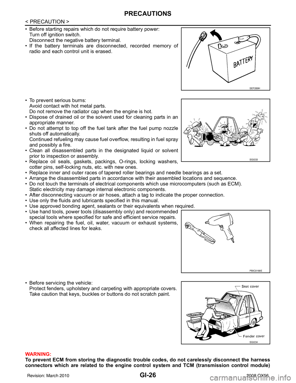
• Before starting repairs which do not require battery power:Turn off ignition switch.
Disconnect the negative battery terminal.
• If the battery terminals are disconnected, recorded memory of radio and each control unit is erased.
• To prevent serious burns: Avoid contact with hot metal parts.
Do not remove the radiator cap when the engine is hot.
• Dispose of drained oil or the solvent used for cleaning parts in an appropriate manner.
• Do not attempt to top off the fuel tank after the fuel pump nozzle
shuts off automatically.
Continued refueling may cause fuel overflow, resulting in fuel spray
and possibly a fire.
• Clean all disassembled parts in the designated liquid or solvent prior to inspection or assembly.
• Replace oil seals, gaskets, packings, O-rings, locking washers,
cotter pins, self-locking nuts, etc. with new ones.
• Replace inner and outer races of tapered roller bearings and needle bearings as a set.
• Arrange the disassembled parts in accordance with their assembled locations and sequence.
• Do not touch the terminals of electrical com ponents which use microcomputers (such as ECM).
Static electricity may damage internal electronic components.
• After disconnecting vacuum or air hoses, atta ch a tag to indicate the proper connection.
• Use only the fluids and lubricants specified in this manual.
• Use approved bonding agent, sealants or their equivalents when required.
• Use hand tools, power tools (disassembly only) and recommended special tools where specified for safe and efficient service repairs.
• When repairing the fuel, oil, water, vacuum or exhaust systems, check all affected lines for leaks.
• Before servicing the vehicle: Protect fenders, upholstery and carpeting with appropriate covers.
Take caution that keys, buckles or buttons do not scratch paint.
WARNING:
To prevent ECM from storing the diagnostic tro uble codes, do not carelessly disconnect the harness
connectors which are related to the engine control system and TCM (transmission control module)
SEF289H
SGI233
PBIC0190E
SGI234
Revision: March 2010 2008 QX56