2008 INFINITI QX56 low beam
[x] Cancel search: low beamPage 1940 of 4083
EXL-12
< FUNCTION DIAGNOSIS >
AUTO LIGHT SYSTEM
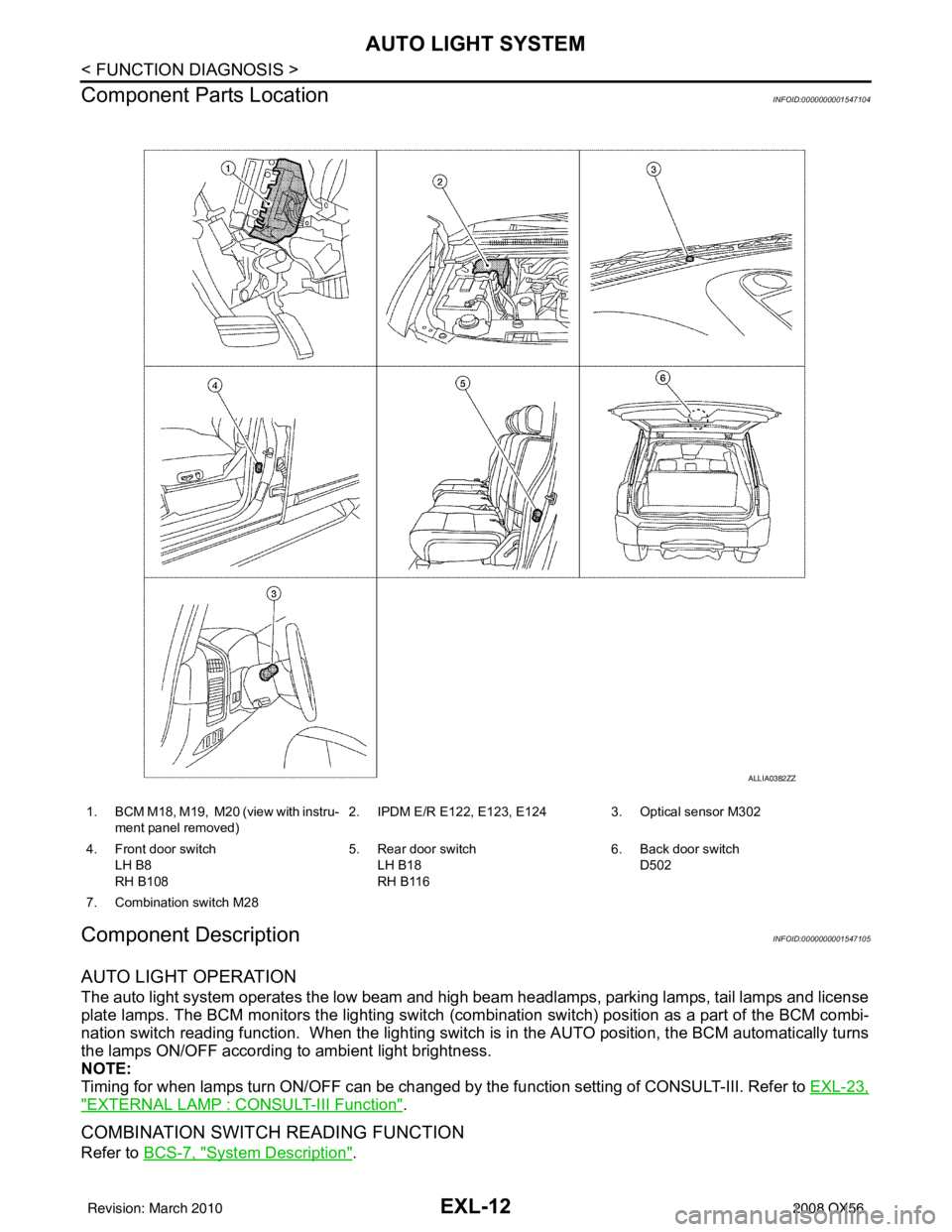
Component Parts Location
INFOID:0000000001547104
Component DescriptionINFOID:0000000001547105
AUTO LIGHT OPERATION
The auto light system operates t he low beam and high beam headlamps, parking lamps, tail lamps and license
plate lamps. The BCM monitors the lighting switch (com bination switch) position as a part of the BCM combi-
nation switch reading function. When the lighting switch is in the AUTO position, the BCM automatically turns
the lamps ON/OFF according to ambient light brightness.
NOTE:
Timing for when lamps turn ON/OFF can be changed by the function setting of CONSULT-III. Refer to EXL-23,
"EXTERNAL LAMP : CONSULT-III Function".
COMBINATION SWITCH READING FUNCTION
Refer to BCS-7, "System Description".
1. BCM M18, M19, M20 (view with instru-
ment panel removed) 2. IPDM E/R E122, E123, E124 3. Optical sensor M302
4. Front door switch LH B8
RH B108 5. Rear door switch
LH B18
RH B116 6. Back door switch
D502
7. Combination switch M28
ALLIA0382ZZ
Revision: March 2010 2008 QX56
Page 1952 of 4083
![INFINITI QX56 2008 Factory Service Manual EXL-24
< FUNCTION DIAGNOSIS >
DIAGNOSIS SYSTEM (BCM)
1: The item is indicated, not monitored
ACTIVE TEST
Monitor item[Unit] Description
IGN ON SW
[ON/OFF] The switch status input from ignition switch
INFINITI QX56 2008 Factory Service Manual EXL-24
< FUNCTION DIAGNOSIS >
DIAGNOSIS SYSTEM (BCM)
1: The item is indicated, not monitored
ACTIVE TEST
Monitor item[Unit] Description
IGN ON SW
[ON/OFF] The switch status input from ignition switch](/manual-img/42/57030/w960_57030-1951.png)
EXL-24
< FUNCTION DIAGNOSIS >
DIAGNOSIS SYSTEM (BCM)
1: The item is indicated, not monitored
ACTIVE TEST
Monitor item[Unit] Description
IGN ON SW
[ON/OFF] The switch status input from ignition switch
ACC ON SW
[ON/OFF] The switch status input from ignition switch
TURN SIGNAL R
[ON/OFF]
Each switch status that BCM judges from the combination switch reading function
TURN SIGNAL L
[ON/OFF]
HI BEAM SW
[ON/OFF]
HEAD LAMP SW1
[ON/OFF]
HEAD LAMP SW2
[ON/OFF]
LIGHT SW 1ST
[ON/OFF]
AUTO LIGHT SW
[ON/OFF]
PASSING SW
[ON/OFF]
FR FOG SW
[ON/OFF]
CARGO LAMP SW
[ON/OFF]
RR FOG SW
1
[ON/OFF]
—
DOOR SW-DR
[ON/OFF] The switch status input from front door switch LH
DOOR SW-AS
[ON/OFF] The switch status input from front door switch RH
DOOR SW-RR
[ON/OFF] The switch status input from rear door switch RH
DOOR SW- RL
[ON/OFF] The switch status input from rear door switch LH
DOOR SW-BK
[ON/OFF] The switch status input from the back door switch
OPTICAL SENSOR
[V] The value of exterior brightness voltage input from the optical sensor
Test item
Operation Description
TA I L L A M P ON
Transmits the position light request signal to IPDM E/R via CAN commu-
nication to turn the tail lamp ON.
OFF Stops the tail lamp request signal transmission.
HEAD LAMP HI
Transmits the high beam request signal via CAN communication to turn
the headlamp (HI)
LO Transmits the low beam request signal via CAN communication to turn
the headlamp (LO).
OFF Stops the high & low beam request signal transmission.
Revision: March 2010 2008 QX56
Page 1954 of 4083

EXL-26
< FUNCTION DIAGNOSIS >
DIAGNOSIS SYSTEM (IPDM E/R)
DIAGNOSIS SYSTEM (IPDM E/R)
CONSULT - III Function (IPDM E/R)INFOID:0000000001547122
APPLICATION ITEM
CONSULT-III performs the following functi ons via CAN communication with IPDM E/R.
DATA MONITOR
Monitor item
ACTIVE TEST
Te s t i t e m
Diagnosis mode Description
Self Diagnostic Result Displays the diagnosis results judged by IPDM E/R.
Data Monitor Displays the real-time input/output data from IPDM E/R input/output data.
Active Test IPDM E/R can provide a drive signal to electronic components to check their operations.
CAN Diag Support Monitor The results of transmit/receive diagnosis of CAN communication can be read.
Monitor Item
[Unit] MAIN SIG-
NALS Description
TAIL & CLR REQ
[Off/On] ×Displays the status of the tail and clearance lamp request signal received from
BCM via CAN communication.
HL LO REQ
[Off/On] ×
Displays the status of the low beam request signal received from BCM via CAN
communication.
HL HI REQ
[Off/On] ×
Displays the status of the high beam request signal received from BCM via CAN
communication.
FR FOG REQ
[Off/On] ×Displays the status of the front fog light request signal received from BCM via
CAN communication.
IGN RLY
[Off/On] ×
Displays the status of the ignition relay judged by the IPDM E/R-.
DTRL REQ
[Off] ×
Displays the status of the daytime light request signal received from the BCM via
CAN communication.
Test item
Operation Description
EXTERNAL LAMPS Off
OFF
TAIL Operates the tail lamp relay.
Lo Operates the headlamp low relay.
Hi Operates the headlamp low relay and ON/OFF the headlamp high relay at 1 sec-
ond intervals.
Fog Operates the front fog lamp relay.
Revision: March 2010 2008 QX56
Page 1956 of 4083
EXL-28
< COMPONENT DIAGNOSIS >
HEADLAMP (HI) CIRCUIT
HEADLAMP (HI) CIRCUIT
DescriptionINFOID:0000000001547125
The IPDM E/R (intelligent power distribution module engine room) controls the headlamp high relay based on
inputs from the BCM via the CAN communication lines. When the headlamp high relay is energized, power
flows through fuses 34 and 35, located in the IPDM E/R. Power then flows to the front combination lamps to
the headlamp high beam.
Component Function CheckINFOID:0000000001547126
1.CHECK HEADLAMP (HI) OPERATION
WITHOUT CONTULT-III
1. Start IPDM E/R auto active test. Refer to PCS-12, "
Diagnosis Description".
2. Check that the headlamp switches to the high beam. NOTE:
HI/LO is repeated 1 second each when usi ng the IPDM E/R auto active test.
CONSULT-III
1. Select "EXTERNAL LAMP" of IPDM E/R active test item.
2. With the test item operating, check that the headlamp switches to high beam.
Does the headlamp switch to high beam?
YES >> Headlamp (HI) circuit is normal.
NO >> Refer to EXL-28, "
Diagnosis Procedure".
Diagnosis ProcedureINFOID:0000000001547127
1.CHECK HEADLAMP (HI) FUSES
1. Turn the ignition switch OFF.
2. Check that the following fuses are not open.
Is the fuse open?
YES >> Repair the harness and replace the fuse.
NO >> GO TO 2
2.CHECK HEADLAMP (HI) OUTPUT VOLTAGE
1. Turn the ignition switch OFF.
2. Disconnect the front combination lamp connector E11 or E107.
3. Turn the ignition switch ON.
4. Turn the high beam headlamps ON.
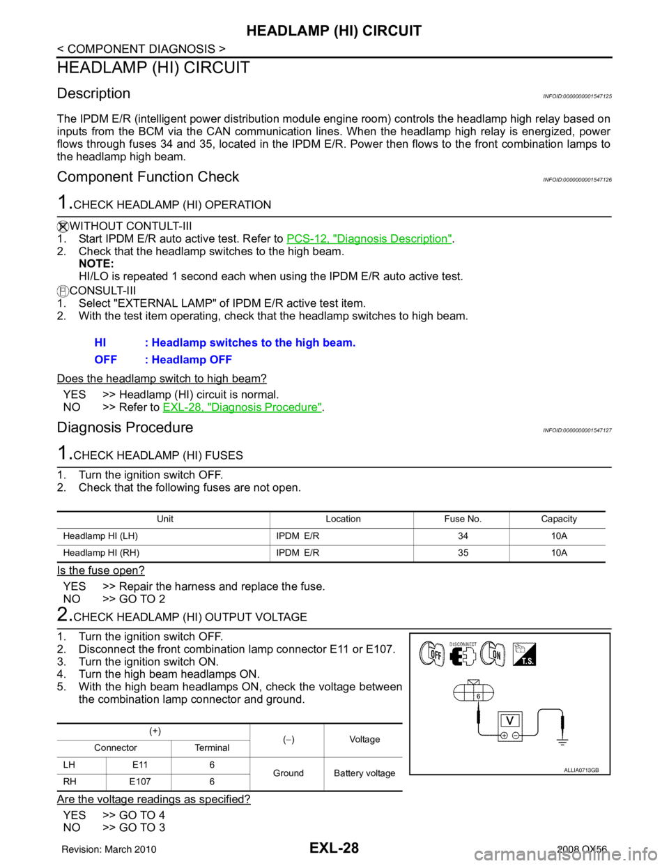
5. With the high beam headlamps ON, check the voltage between the combination lamp connector and ground.
Are the voltage readings as specified?
YES >> GO TO 4
NO >> GO TO 3 HI : Headlamp switches to the high beam.
OFF : Headlamp OFF
Unit
LocationFuse No.Capacity
Headlamp HI (LH) IPDM E/R3410A
Headlamp HI (RH) IPDM E/R3510A
(+)
(−)Voltage
Connector Terminal
LH E11 6
Ground Battery voltage
RH E107 6
ALLIA0713GB
Revision: March 2010 2008 QX56
Page 1958 of 4083
EXL-30
< COMPONENT DIAGNOSIS >
HEADLAMP (LO) CIRCUIT
HEADLAMP (LO) CIRCUIT
DescriptionINFOID:0000000001547128
The IPDM E/R (intelligent power distribution module engine room) controls the headlamp low relay based on
inputs from the BCM via the CAN communication lines. When the headlamp low relay is energized, power
flows through fuses 40 and 41, located in the IPDM E/R. Power then flows to the front combination lamps to
the headlamp low beam.
Component Function CheckINFOID:0000000001547129
1.CHECK HEADLAMP (LO) OPERATION
WITHOUT CONSULT-III
1. Start IPDM E/R auto active test. Refer to PCS-12, "
Diagnosis Description".
2. Check that the headlamp is turned ON. NOTE:
HI/LO is repeated 1 second each when usi ng the IPDM E/R auto active test.
CONSULT-III
1. Select "EXTERNAL LAMP" of IPDM E/R active test item.
2. With the test items operating, check that the headlamp is turned ON.
Is the headlamp turned ON?
YES >> Headlamp (LO) is normal.
NO >> Refer to EXL-30, "
Diagnosis Procedure".
Diagnosis ProcedureINFOID:0000000001547130
1.CHECK HEADLAMP (LO) FUSES
1. Turn the ignition switch OFF.
2. Check that the following fuses are not open.
Is the fuse open?
YES >> Repair the harness and replace the fuse.
NO >> GO TO 2
2.CHECK HEADLAMP (LO) OUTPUT VOLTAGE
1. Turn the ignition switch OFF.
2. Disconnect the front combination lamp connector.
3. Turn the ignition switch ON.
4. Turn the low beam headlamps ON.
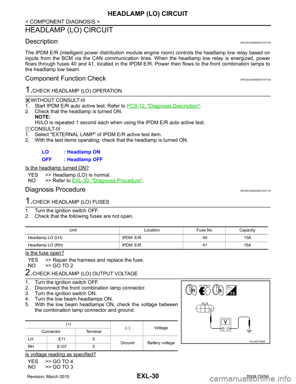
5. With the low beam headlamps ON, check the voltage between the combination lamp connector and ground.
Is voltage reading as specified?
YES >> GO TO 4
NO >> GO TO 3 LO : Headlamp ON
OFF : Headlamp OFF
Unit
LocationFuse No.Capacity
Headlamp LO (LH) IPDM E/R4015A
Headlamp LO (RH) IPDM E/R4115A
(+)
(−)Voltage
Connector Terminal
LH E11 5 Ground Battery voltage
RH E107 5
ALLIA0716GB
Revision: March 2010 2008 QX56
Page 2029 of 4083
EXTERIOR LIGHTING SYSTEM SYMPTOMSEXL-101
< SYMPTOM DIAGNOSIS >
C
DE
F
G H
I
J
K
M A
B
EXL
N
O P
SYMPTOM DIAGNOSIS
EXTERIOR LIGHTING SYSTEM SYMPTOMS
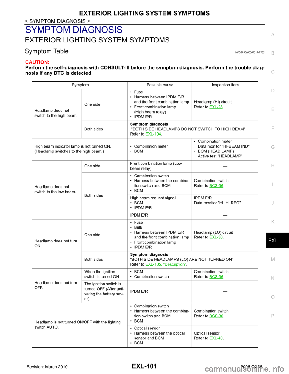
Symptom TableINFOID:0000000001547153
CAUTION:
Perform the self-diagnosis with CONS ULT-III before the symptom diagnosis. Perform the trouble diag-
nosis if any DTC is detected.
Symptom Possible causeInspection item
Headlamp does not
switch to the high beam. One side•Fuse
• Harness between IPDM E/R
and the front combination lamp
• Front combination lamp
(High beam relay)
• IPDM E/R Headlamp (HI) circuit
Refer to
EXL-28
.
Both sides Symptom diagnosis
"BOTH SIDE HEADLAMPS DO NOT SWITCH TO HIGH BEAM"
Refer to EXL-104
.
High beam indicator lamp is not turned ON.
(Headlamp switches to the high beam.) • Combination meter
•BCM• Combination meter.
Data monitor "HI-BEAM IND"
• BCM (HEAD LAMP) Active test "HEADLAMP"
Headlamp does not
switch to the low beam. One side
Front combination lamp (Low
beam relay)
—
Both sides • Combination switch
• Harness between the combina-
tion switch and BCM
•BCM Combination switch
Refer to
BCS-36
.
High beam request signal
•BCM
• IPDM E/R IPDM E/R
Data monitor "HL HI REQ"
IPDM E/R —
Headlamp does not turn
ON. One side•Fuse
•Bulb
• Harness between IPDM E/R
and the front combination lamp
• Front combination lamp
• IPDM E/R Headlamp (LO) circuit
Refer to
EXL-30
.
Both sides Symptom diagnosis
"BOTH SIDE HEADLAMPS (LO) ARE NOT TURNED ON"
Refer to EXL-105, "
Description".
Headlamp does not turn
OFF. When the ignition
switch is turned ON
•BCM
• Combination switch Combination switch
Refer to
BCS-36
.
The ignition switch is
turned OFF (After acti-
vating the battery sav-
er). IPDM E/R
—
Headlamp is not turned ON/OFF with the lighting
switch AUTO. • Combination switch
• Harness between the combina-
tion switch and BCM
•BCM Combination switch
Refer to
BCS-36
.
• Optical sensor
• Harness between the optical sensor and BCM
•BCM Optical sensor
Refer to
EXL-40
.
Revision: March 2010 2008 QX56
Page 2038 of 4083
EXL-110
< ON-VEHICLE REPAIR >
ADJUSTMENT AND INSPECTION
ON-VEHICLE REPAIR
ADJUSTMENT AND INSPECTION
HEADLAMP
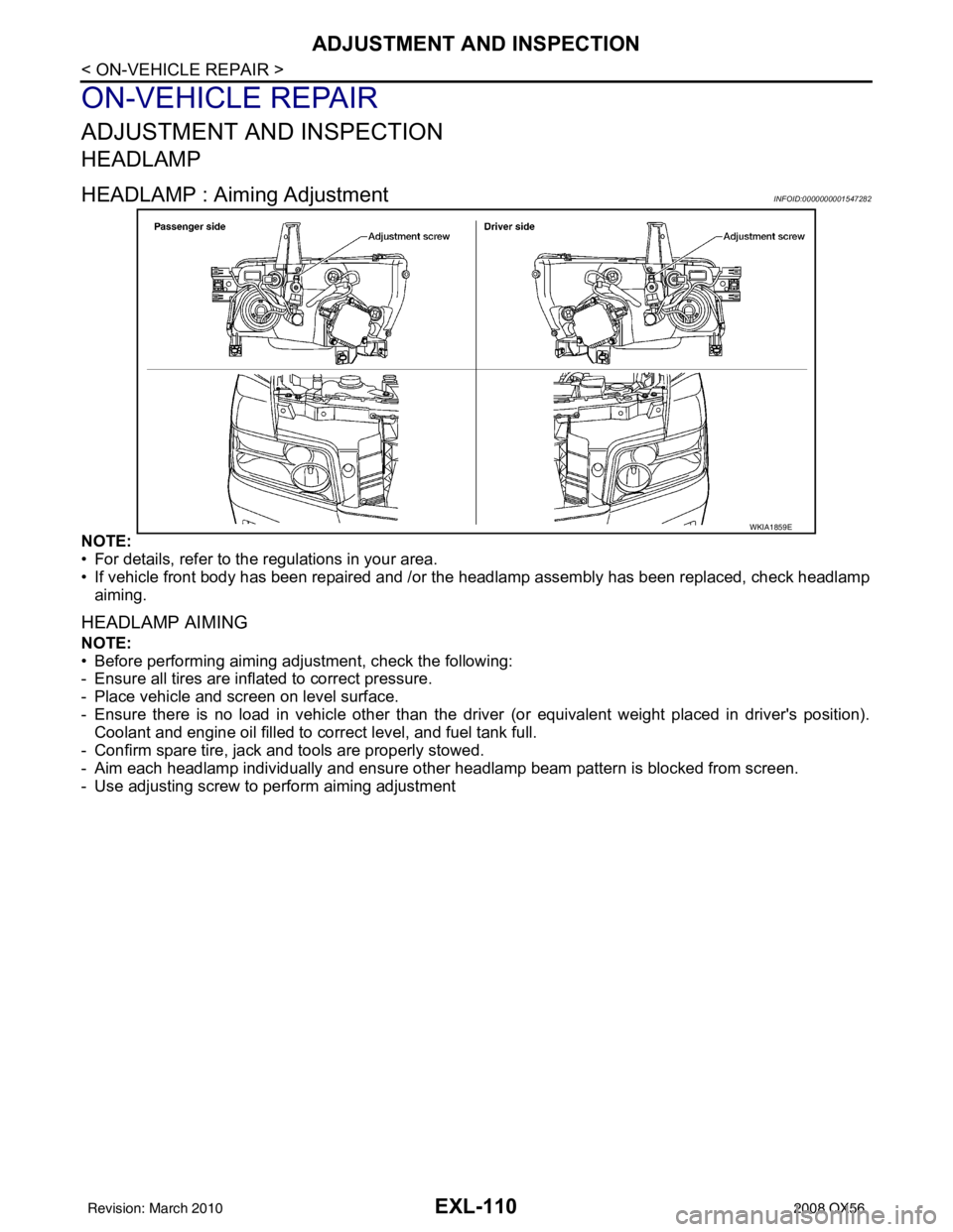
HEADLAMP : Aiming AdjustmentINFOID:0000000001547282
NOTE:
• For details, refer to the regulations in your area.
• If vehicle front body has been repaired and /or the headlamp assembly has been replaced, check headlamp
aiming.
HEADLAMP AIMING
NOTE:
• Before performing aiming adjustment, check the following:
- Ensure all tires are inflated to correct pressure.
- Place vehicle and screen on level surface.
- Ensure there is no load in vehicle other than the driver (or equivalent weight placed in driver's position).
Coolant and engine oil filled to correct level, and fuel tank full.
- Confirm spare tire, jack and tools are properly stowed.
- Aim each headlamp individually and ensure other headlamp beam pattern is blocked from screen.
- Use adjusting screw to perform aiming adjustment
WKIA1859E
Revision: March 2010 2008 QX56
Page 2039 of 4083
ADJUSTMENT AND INSPECTIONEXL-111
< ON-VEHICLE REPAIR >
C
DE
F
G H
I
J
K
M A
B
EXL
N
O P
NOTE:
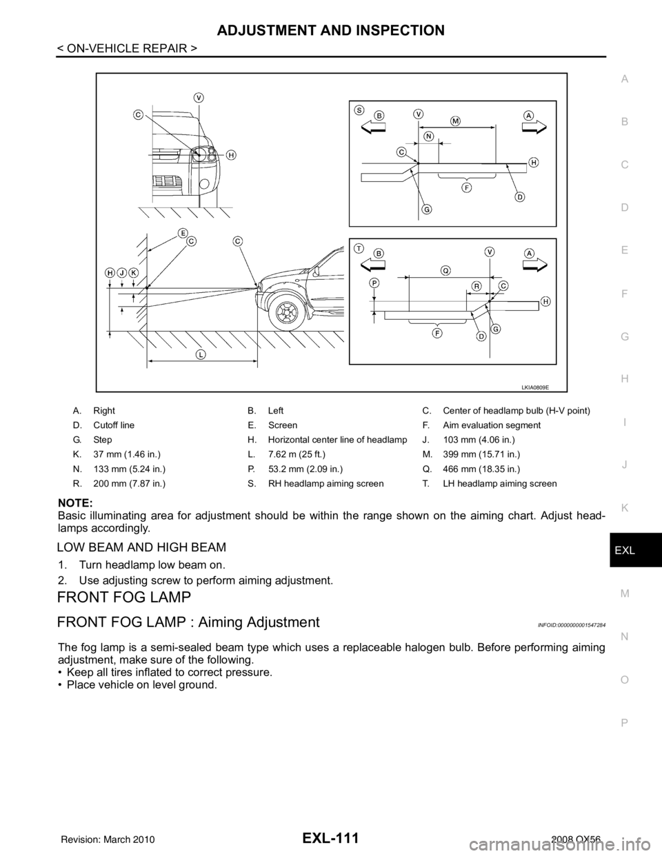
Basic illuminating area for adjustment should be within the range shown on the aiming chart. Adjust head-
lamps accordingly.
LOW BEAM AND HIGH BEAM
1. Turn headlamp low beam on.
2. Use adjusting screw to perform aiming adjustment.
FRONT FOG LAMP
FRONT FOG LAMP : Aiming AdjustmentINFOID:0000000001547284
The fog lamp is a semi-sealed beam type which uses a replaceable halogen bulb. Before performing aiming
adjustment, make sure of the following.
• Keep all tires inflated to correct pressure.
• Place vehicle on level ground.
A. Right B. LeftC. Center of headlamp bulb (H-V point)
D. Cutoff line E. ScreenF. Aim evaluation segment
G. Step H. Horizontal center line of headlamp J. 103 mm (4.06 in.)
K. 37 mm (1.46 in.) L. 7.62 m (25 ft.)M. 399 mm (15.71 in.)
N. 133 mm (5.24 in.) P. 53.2 mm (2.09 in.)Q. 466 mm (18.35 in.)
R. 200 mm (7.87 in.) S. RH headlamp aiming screen T. LH headlamp aiming screen
LKIA0809E
Revision: March 2010 2008 QX56