2008 INFINITI QX56 wheel
[x] Cancel search: wheelPage 2167 of 4083
PRECAUTIONSGI-25
< PRECAUTION >
C
DE
F
G H
I
J
K L
M B
GI
N
O P
2. Use the Intelligent Key or mechanical key to turn the ignition switch to the ″ACC ″ position. At this time, the
steering lock will be released.
3. Disconnect both battery cables. The steering lock will remain released and the steering wheel can be
rotated.
4. Perform the necessary repair operation.
5. When the repair work is completed, return the ignition switch to the ″LOCK ″ position before connecting
the battery cables. (At this time, the steering lock mechanism will engage.)
6. Perform a self-diagnosis check of al l control units using CONSULT-III.
Procedures without Cowl Top CoverINFOID:0000000001539208
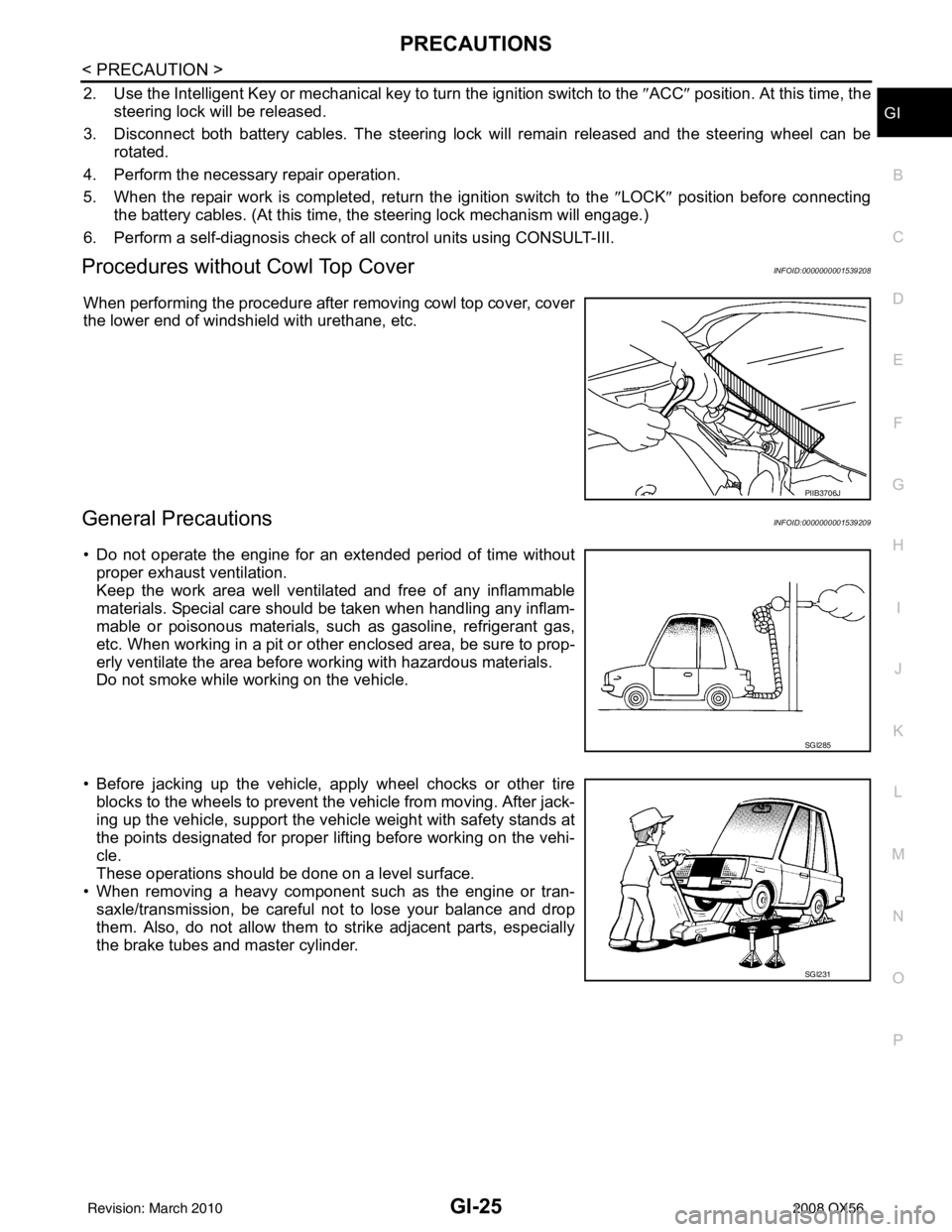
When performing the procedure after removing cowl top cover, cover
the lower end of windshield with urethane, etc.
General PrecautionsINFOID:0000000001539209
• Do not operate the engine for an extended period of time without
proper exhaust ventilation.
Keep the work area well ventilated and free of any inflammable
materials. Special care should be taken when handling any inflam-
mable or poisonous materials, such as gasoline, refrigerant gas,
etc. When working in a pit or ot her enclosed area, be sure to prop-
erly ventilate the area before working with hazardous materials.
Do not smoke while working on the vehicle.
• Before jacking up the vehicle, apply wheel chocks or other tire blocks to the wheels to prevent t he vehicle from moving. After jack-
ing up the vehicle, support the vehicle weight with safety stands at
the points designated for proper lifting before working on the vehi-
cle.
These operations should be done on a level surface.
• When removing a heavy component such as the engine or tran-
saxle/transmission, be careful not to lose your balance and drop
them. Also, do not allow them to strike adjacent parts, especially
the brake tubes and master cylinder.
PIIB3706J
SGI285
SGI231
Revision: March 2010 2008 QX56
Page 2172 of 4083
GI-30
< PRECAUTION >
LIFTING POINT
LIFTING POINT
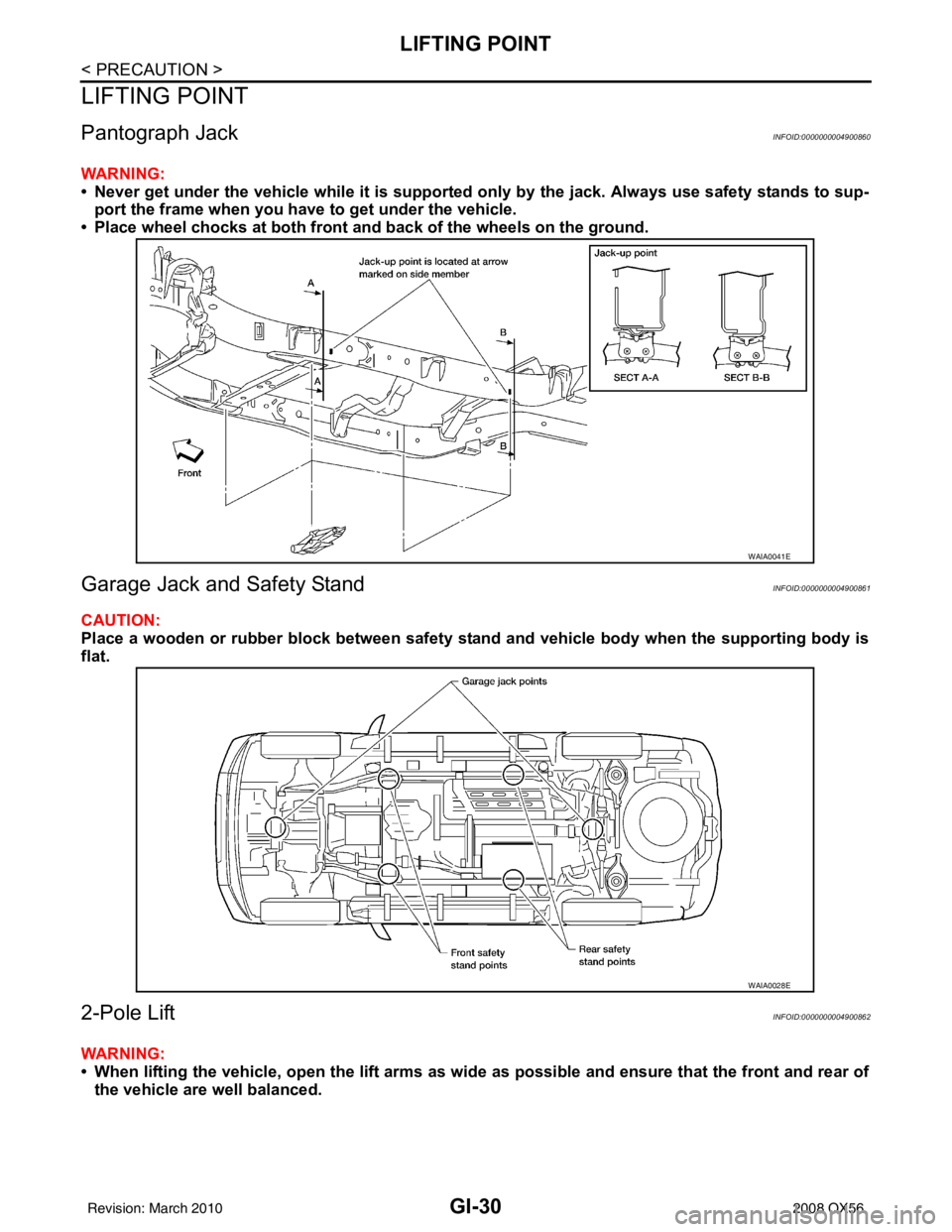
Pantograph JackINFOID:0000000004900860
WARNING:
• Never get under the vehicle while it is supported only by the jack. Always use safety stands to sup-
port the frame when you have to get under the vehicle.
• Place wheel chocks at both front an d back of the wheels on the ground.
Garage Jack and Safety StandINFOID:0000000004900861
CAUTION:
Place a wooden or rubber block between safety stand and vehicle body when the supporting body is
flat.
2-Pole LiftINFOID:0000000004900862
WARNING:
• When lifting the vehicle, open the lift arms as wid e as possible and ensure that the front and rear of
the vehicle are well balanced.
WAIA0041E
WAIA0028E
Revision: March 2010 2008 QX56
Page 2174 of 4083
GI-32
< PRECAUTION >
TOW TRUCK TOWING
TOW TRUCK TOWING
Tow Truck TowingINFOID:0000000004900863
WARNING:
• Never get under the vehicle while it is supported only by the jack. Always use safety stands to sup-
port the frame when you have to get under the vehicle.
• Place wheel chocks at both front an d back of the wheels on the ground.
CAUTION:
• All applicable local laws regarding the towing operation must be obeyed.
• It is necessary to use proper towing equipment to avoid possible damage during towing operation.
Towing is in accordance with Towing Procedure Manual at dealer.
• Always attach safety chains before towing.
• When towing, make sure that the transmission, steering system and power train are in good order. If
any unit is damaged, dollies must be used.
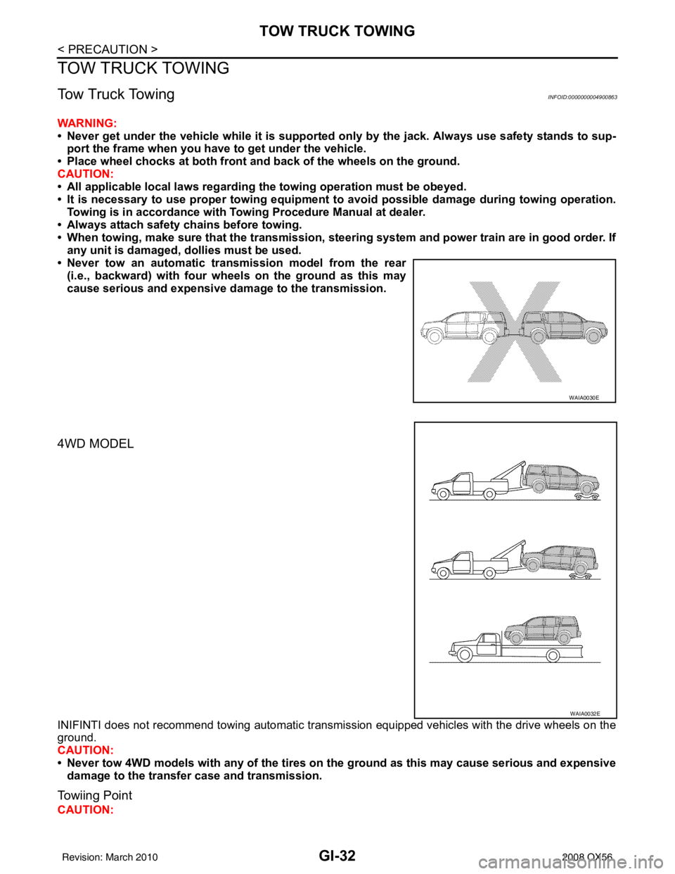
• Never tow an automatic transmission model from the rear
(i.e., backward) with four wh eels on the ground as this may
cause serious and expensive dama ge to the transmission.
4WD MODEL
INIFINTI does not recommend towing automatic transmi ssion equipped vehicles with the drive wheels on the
ground.
CAUTION:
• Never tow 4WD models with any of the tires on the ground as this may cause serious and expensive
damage to the transfer case and transmission.
Towiing Point
CAUTION:
WAIA0030E
WAIA0032E
Revision: March 2010 2008 QX56
Page 2189 of 4083
CONSULT-III CHECKING SYSTEMGI-47
< BASIC INSPECTION >
C
DE
F
G H
I
J
K L
M B
GI
N
O P
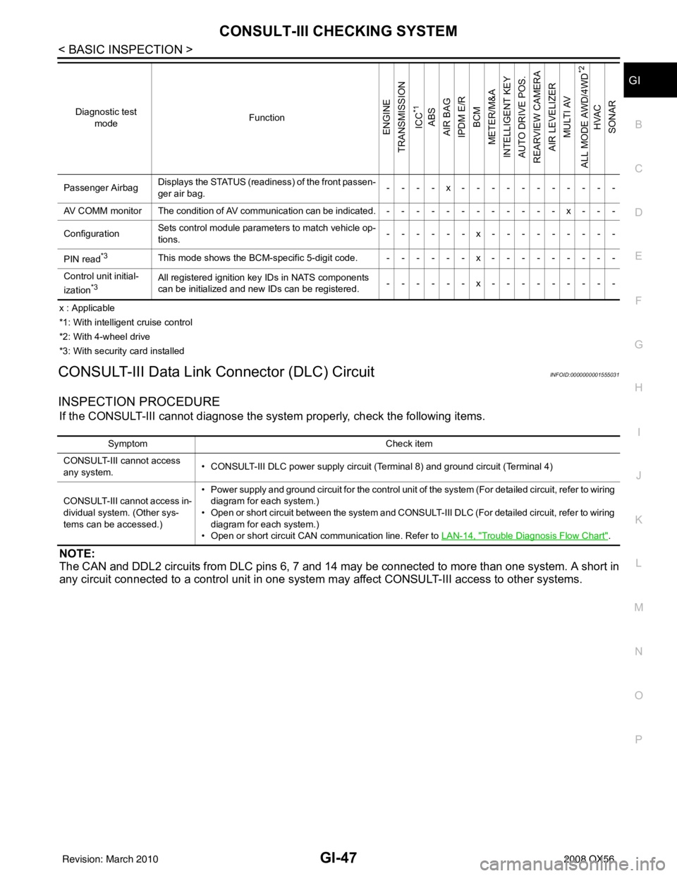
x : Applicable
*1: With intelligent cruise control
*2: With 4-wheel drive
*3: With security card installed
CONSULT-III Data Link Connector (DLC) CircuitINFOID:0000000001555031
INSPECTION PROCEDURE
If the CONSULT-III cannot diagnose the sys tem properly, check the following items.
NOTE:
The CAN and DDL2 circuits from DLC pins 6, 7 and 14 may be connected to more than one system. A short in
any circuit connected to a control unit in one system may affect CONSULT-III access to other systems.
Passenger AirbagDisplays the STATUS (readiness) of the front passen-
ger air bag. ----x-----------
AV COMM monitor The condition of AV communication can be indicated.------------x---
Configuration Sets control module parame
ters to match vehicle op-
tions. ------x---------
PIN read
*3This mode shows the BCM-specific 5-digit code. ------x---------
Control unit initial-
ization
*3All registered ignition key IDs in NATS components
can be initialized and new IDs can be registered. ------x---------
Diagnostic test
mode Function
ENGINE
TRANSMISSION
ICC
*1
ABS
AIR BAG
IPDM E/R BCM
METER/M&A
INTELLIGENT KEY
AUTO DRIVE POS.
REARVIEW CAMERA AIR LEVELIZER MULTI AV
ALL MODE AWD/4WD
*2
HVAC
SONAR
Symptom Check item
CONSULT-III cannot access
any system. • CONSULT-III DLC power supply circuit (Terminal 8) and ground circuit (Terminal 4)
CONSULT-III cannot access in-
dividual system. (Other sys-
tems can be accessed.) • Power supply and ground circuit for the control unit of the system (For detailed circuit, refer to wiring
diagram for each system.)
• Open or short circuit between the system and CONSULT-III DLC (For detailed circuit, refer to wiring diagram for each system.)
• Open or short circuit CAN communication line. Refer to LAN-14, "
Trouble Diagnosis Flow Chart".
Revision: March 2010 2008 QX56
Page 2191 of 4083

GW-1
BODY EXTERIOR, DOORS, ROOF & VEHICLE SECURITY
C
DE
F
G H
I
J
L
M
SECTION GW
A
B
GW
N
O P
CONTENTS
GLASS & WINDOW SYSTEM
PRECAUTION ....... ........................................2
PRECAUTIONS .............................................. .....2
Precaution for Supplemental Restraint System
(SRS) "AIR BAG" and "SEAT BELT PRE-TEN-
SIONER" ............................................................. ......
2
Precaution Necessary for Steering Wheel Rota-
tion After Battery Disconnect ............................... ......
2
Handling for Adhesive and Primer ............................3
PREPARATION ............................................4
PREPARATION .............................................. .....4
Special Service Tool ........................................... ......4
Commercial Service Tool ..........................................4
ON-VEHICLE REPAIR ..................................5
WINDSHIELD GLASS ........................................5
Removal and Installation ..................................... .....5
REAR WINDOW GLASS AND MOLDING .........7
Removal and Installation ..........................................7
FRONT DOOR GLASS AND REGULATOR ......9
Removal and Installation ..........................................9
REAR DOOR GLASS AND REGULATOR .......13
Removal and Installation .........................................13
SIDE WINDOW GLASS ....................................15
Removal and Installation .........................................15
Revision: March 2010 2008 QX56
Page 2192 of 4083
GW-2
< PRECAUTION >
PRECAUTIONS
PRECAUTION
PRECAUTIONS
Precaution for Supplemental Restraint System (SRS) "AIR BAG" and "SEAT BELT
PRE-TENSIONER"
INFOID:0000000004884108
The Supplemental Restraint System such as “A IR BAG” and “SEAT BELT PRE-TENSIONER”, used along
with a front seat belt, helps to reduce the risk or severity of injury to the driver and front passenger for certain
types of collision. This system includes seat belt switch inputs and dual stage front air bag modules. The SRS
system uses the seat belt switches to determine the front air bag deployment, and may only deploy one front
air bag, depending on the severity of a collision and w hether the front occupants are belted or unbelted.
Information necessary to service the system safely is included in the SR and SB section of this Service Man-
ual.
WARNING:
• To avoid rendering the SRS inopera tive, which could increase the risk of personal injury or death in
the event of a collision which would result in air bag inflation, all maintenance must be performed by
an authorized NISSAN/INFINITI dealer.
• Improper maintenance, including in correct removal and installation of the SRS, can lead to personal
injury caused by unintent ional activation of the system. For re moval of Spiral Cable and Air Bag
Module, see the SR section.
• Do not use electrical test equipmen t on any circuit related to the SRS unless instructed to in this
Service Manual. SRS wiring harn esses can be identified by yellow and/or orange harnesses or har-
ness connectors.
PRECAUTIONS WHEN USING POWER TOOLS (AIR OR ELECTRIC) AND HAMMERS
WARNING:
• When working near the Airbag Diagnosis Sensor Unit or other Airbag System sensors with the Igni-
tion ON or engine running, DO NOT use air or electri c power tools or strike near the sensor(s) with a
hammer. Heavy vibration could activate the sensor( s) and deploy the air bag(s), possibly causing
serious injury.
• When using air or electric power tools or hammers , always switch the Ignition OFF, disconnect the
battery, and wait at least 3 minu tes before performing any service.
Precaution Necessary for Steering W heel Rotation After Battery Disconnect
INFOID:0000000004881261
NOTE:
• This Procedure is applied only to models with Intelligent Key system and NATS (NISSAN ANTI-THEFT SYS-
TEM).
• Remove and install all control units after disconnecting both battery cables with the ignition knob in the
″LOCK ″ position.
• Always use CONSULT-III to perform self-diagnosis as a part of each function inspection after finishing work.
If DTC is detected, perform trouble diagnosis according to self-diagnostic results.
For models equipped with the Intelligent Key system and NATS, an electrically controlled steering lock mech-
anism is adopted on the key cylinder.
For this reason, if the battery is disconnected or if the battery is discharged, the steering wheel will lock and
steering wheel rotation will become impossible.
If steering wheel rotation is required when battery pow er is interrupted, follow the procedure below before
starting the repair operation.
OPERATION PROCEDURE
1. Connect both battery cables. NOTE:
Supply power using jumper cables if battery is discharged.
2. Use the Intelligent Key or mechanical key to turn the ignition switch to the ″ACC ″ position. At this time, the
steering lock will be released.
3. Disconnect both battery cables. The steering lock will remain released and the steering wheel can be rotated.
4. Perform the necessary repair operation.
Revision: March 2010 2008 QX56
Page 2206 of 4083

HA-1
VENTILATION, HEATER & AIR CONDITIONER
C
DE
F
G H
J
K L
M
SECTION HA
A
B
HA
N
O P
CONTENTS
HEATER & AIR CONDITIONING SYSTEM
PRECAUTION ....... ........................................3
PRECAUTIONS .............................................. .....3
Precaution for Supplemental Restraint System
(SRS) "AIR BAG" and "SEAT BELT PRE-TEN-
SIONER" ............................................................. ......
3
Precaution Necessary for Steering Wheel Rota-
tion After Battery Disconnect ............................... ......
3
Precaution for Working with HFC-134a (R-134a) ......4
Precaution for Procedure without Cowl Top Cover ......4
Contaminated Refrigerant .........................................4
General Refrigerant Precaution ................................5
Precaution for Leak Detection Dye ...........................5
A/C Identification Label .............................................5
Precaution for Refrigerant Connection ......................5
Precaution for Service of Compressor ................ ....10
Precaution for Service Equipment ....................... ....10
PREPARATION ...........................................13
PREPARATION .............................................. ....13
Special Service Tool ........................................... ....13
HFC-134a (R-134a) Service Tool and Equipment ....13
Commercial Service Tool ........................................16
FUNCTION DIAGNOSIS ..............................17
REFRIGERATION SYSTEM .......................... ....17
Refrigerant Cycle ................................................ ....17
Refrigerant System Protection ................................17
OIL .................................................................. ....19
Maintenance of Oil in Compressor ...................... ....19
ON-VEHICLE MAINTENANCE ....................20
REFRIGERATION SYSTEM .......................... ....20
HFC-134a (R-134a) Service Procedure ..................20
OIL .................................................................. ....22
Maintenance of Oil Quantity in Compressor ....... ....22
FLUORESCENT LEAK DETECTOR ................24
Checking of Refrigerant Leaks ................................24
Checking System for Leaks Using the Fluorescent
Dye Leak Detector ............................................... ....
24
Dye Injection ............................................................24
ELECTRICAL LEAK DETECTOR ....................26
Checking of Refrigerant Leaks ................................26
Electronic Refrigerant Leak Detector ................... ....26
ON-VEHICLE REPAIR .................................29
REFRIGERATION SYSTEM .............................29
Component .......................................................... ....29
COMPRESSOR .................................................31
Removal and Installation for Compressor ...............31
Removal and Installation for Compressor Clutch ....32
LOW-PRESSURE FLEXIBLE HOSE ................36
Removal and Installation for Low-Pressure Flexi-
ble Hose .............................................................. ....
36
LOW-PRESSURE PIPE ....................................37
Removal and Installation for Low-Pressure Pipe .....37
Removal and Installation for Rear High- and Low-
Pressure A/C and Heater Core Pipes ......................
37
Removal and Installation for Underfloor Rear
High- and Low-Pressure A/C and Heater Core
Pipes ........................................................................
38
HIGH-PRESSURE FLEXIBLE HOSE ...............40
Removal and Installation for High-Pressure Flexi-
ble Hose ..................................................................
40
HIGH-PRESSURE PIPE ....................................41
Removal and Installation for High-Pressure Pipe ....41
Removal and Installation for Rear High- and Low-
Pressure A/C and Heater Core Pipes .................. ....
41
Removal and Installation for Underfloor Rear
High- and Low-Pressure A/C and Heater Core
Pipes ........................................................................
43
Revision: March 2010 2008 QX56
Page 2208 of 4083
PRECAUTIONSHA-3
< PRECAUTION >
C
DE
F
G H
J
K L
M A
B
HA
N
O P
PRECAUTION
PRECAUTIONS
Precaution for Supplemental Restraint System (SRS) "AIR BAG" and "SEAT BELT
PRE-TENSIONER"
INFOID:0000000004884163
The Supplemental Restraint System such as “AIR BAG” and “SEAT BELT PRE-TENSIONER”, used along
with a front seat belt, helps to reduce the risk or severi ty of injury to the driver and front passenger for certain
types of collision. This system includes seat belt switch inputs and dual stage front air bag modules. The SRS
system uses the seat belt switches to determine the front air bag deployment, and may only deploy one front
air bag, depending on the severity of a collision and w hether the front occupants are belted or unbelted.
Information necessary to service the system safely is included in the SR and SB section of this Service Man-
ual.
WARNING:
• To avoid rendering the SRS inoper ative, which could increase the risk of personal injury or death in
the event of a collision which would result in air bag inflation, all maintenance must be performed by
an authorized NISSAN/INFINITI dealer.
• Improper maintenance, including in correct removal and installation of the SRS, can lead to personal
injury caused by unintentional act ivation of the system. For removal of Spiral Cable and Air Bag
Module, see the SR section.
• Do not use electrical test equipm ent on any circuit related to the SRS unless instructed to in this
Service Manual. SRS wiring harnesses can be identi fied by yellow and/or orange harnesses or har-
ness connectors.
PRECAUTIONS WHEN USING POWER TOOLS (AIR OR ELECTRIC) AND HAMMERS
WARNING:
• When working near the Airbag Diagnosis Sensor Un it or other Airbag System sensors with the Igni-
tion ON or engine running, DO NOT use air or el ectric power tools or strike near the sensor(s) with a
hammer. Heavy vibration could activate the sensor( s) and deploy the air bag(s), possibly causing
serious injury.
• When using air or electric power tools or hammers, always switch the Ignition OFF, disconnect the battery, and wait at least 3 minutes before performing any service.
Precaution Necessary for Steering Wheel Rotation After Battery Disconnect
INFOID:0000000004884164
NOTE:
• This Procedure is applied only to models with Intelligent Key system and NATS (NISSAN ANTI-THEFT SYS-
TEM).
• Remove and install all control units after disconnecti ng both battery cables with the ignition knob in the
″ LOCK ″ position.
• Always use CONSULT-III to perform self-diagnosis as a part of each function inspection after finishing work.
If DTC is detected, perform trouble diagnosis according to self-diagnostic results.
For models equipped with the Intelligent Key system and NATS , an electrically controlled steering lock mech-
anism is adopted on the key cylinder.
For this reason, if the battery is disconnected or if the battery is discharged, the steering wheel will lock and
steering wheel rotation will become impossible.
If steering wheel rotation is required when battery power is interrupted, follow the procedure below before
starting the repair operation.
OPERATION PROCEDURE
1. Connect both battery cables. NOTE:
Supply power using jumper cables if battery is discharged.
2. Use the Intelligent Key or mechanical key to turn the ignition switch to the ″ACC ″ position. At this time, the
steering lock will be released.
3. Disconnect both battery cables. The steering lock will remain released and the steering wheel can be
rotated.
4. Perform the necessary repair operation.
Revision: March 2010 2008 QX56