2008 INFINITI QX56 brake
[x] Cancel search: brakePage 1764 of 4083
![INFINITI QX56 2008 Factory Service Manual ECM
EC-465
< ECU DIAGNOSIS > [VK56DE]
C
D
E
F
G H
I
J
K L
M A
EC
NP
OOUTPUT SPEED SENSOR*6P0720
0720—2×TM-48
1GR INCORRECT RATIO P07310731—2×TM-53
2GR INCORRECT RATIO P07320732—2×TM-55
3GR IN INFINITI QX56 2008 Factory Service Manual ECM
EC-465
< ECU DIAGNOSIS > [VK56DE]
C
D
E
F
G H
I
J
K L
M A
EC
NP
OOUTPUT SPEED SENSOR*6P0720
0720—2×TM-48
1GR INCORRECT RATIO P07310731—2×TM-53
2GR INCORRECT RATIO P07320732—2×TM-55
3GR IN](/manual-img/42/57030/w960_57030-1763.png)
ECM
EC-465
< ECU DIAGNOSIS > [VK56DE]
C
D
E
F
G H
I
J
K L
M A
EC
NP
OOUTPUT SPEED SENSOR*6P0720
0720—2×TM-48
1GR INCORRECT RATIO P07310731—2×TM-53
2GR INCORRECT RATIO P07320732—2×TM-55
3GR INCORRECT RATIO P07330733—2×TM-57
4GR INCORRECT RATIO P07340734—2×TM-59
5GR INCORRECT RATIO P07350735—2×TM-61
TORQUE CONVERTER P07400740—2×TM-63
TORQUE CONVERTER P07440744—2×TM-65
PC SOLENOID A P07450745—2×TM-67
P-N POS SW/CIRCUIT P08500850—2×EC-296
INTK TIM S/CIRC-B1 P11401140—2×EC-299
INTK TIM S/CIRC-B2 P11451145—2×EC-299
CLOSED LOOP-B1 P11481148—1×EC-303
CLOSED LOOP-B2 P11681168—1×EC-303
TCS C/U FUNCTN P12111211—2—EC-304
TCS/CIRC P12121212—2—EC-305
ENG OVER TEMP P12171217—1×EC-36
CTP LEARNING-B1 P12251225—2—EC-310
CTP LEARNING-B1 P12261226—2—EC-312
COLD START CONTROL P14211421—2×EC-314
BAT CURRENT SENSOR P15501550—2—EC-316
BAT CURRENT SENSOR P15511551—2—EC-320
BAT CURRENT SENSOR P15521552—2—EC-320
BAT CURRENT SENSOR P15531553—2—EC-324
BAT CURRENT SENSOR P15541554—2—EC-328
ASCD SW P15641564—1—EC-332
(Models
with ICC) EC-336
(Models
with ASCD)
ICC COMMAND VALUE*
9P1568 1568—1—EC-340
ASCD BRAKE SW P15721572—1—EC-341
(Models
with ICC) EC-347
(Models
with ASCD)
ASCD VHL SPD SEN*
8P1574 1574—1—EC-352
(Models
with ICC)
EC-354
(Models
with ASCD)
ID DISCARD IMM-ECM P16111611—2—SEC-39
CHAIN OF ECM-IMMU P16121612—2—SEC-35
CHAIN OF IMMU-KEY P16141614—2—SEC-29
Items
(CONSULT-IIl screen terms) DTC*
1
SRT code Trip
MILReference
page
CONSULT-IIl
GST*
2ECM*3
Revision: March 2010 2008 QX56
Page 1765 of 4083
![INFINITI QX56 2008 Factory Service Manual EC-466
< ECU DIAGNOSIS >[VK56DE]
ECM
*1: 1st trip DTC No. is the same as DTC No.
*2: This number is prescribed by SAE J2012.
*3: In Diagnostic Test
Mode II (Self-diagnostic results), this number is INFINITI QX56 2008 Factory Service Manual EC-466
< ECU DIAGNOSIS >[VK56DE]
ECM
*1: 1st trip DTC No. is the same as DTC No.
*2: This number is prescribed by SAE J2012.
*3: In Diagnostic Test
Mode II (Self-diagnostic results), this number is](/manual-img/42/57030/w960_57030-1764.png)
EC-466
< ECU DIAGNOSIS >[VK56DE]
ECM
*1: 1st trip DTC No. is the same as DTC No.
*2: This number is prescribed by SAE J2012.
*3: In Diagnostic Test
Mode II (Self-diagnostic results), this number is controlled by NISSAN.
*4: SRT code will not be set if the self-diagnostic result is NG.
*5: The troubleshooting for this DTC needs CONSULT-III.
*6: When the fail-safe operations for both self-diagnoses occur, the MIL illuminates.
*7: When the ECM is in the mode of displaying SRT status, MIL may flash. For the details, refer to "How to Display SRT Status".
*8: 2WD models
*9: Models with ICC
*10: Models without ICC
Emission-related Diagnostic InformationINFOID:0000000001534998
DTC AND 1ST TRIP DTC
The 1st trip DTC (whose number is the same as the DT C number) is displayed for the latest self-diagnostic
result obtained. If the ECM memory was cleared previous ly, and the 1st trip DTC did not reoccur, the 1st trip
DTC will not be displayed.
If a malfunction is detected during the 1st trip, the 1st trip DTC is stored in the ECM memory. The MIL will not
light up (two trip detection logic). If the same malfunction is not detected in the 2nd trip (meeting the required
driving pattern), the 1st trip DTC is cleared from the ECM memory. If the same malfunction is detected in the
2nd trip, both the 1st trip DTC and DTC are stored in t he ECM memory and the MIL lights up. In other words,
the DTC is stored in the ECM memory and the MIL light s up when the same malfunction occurs in two consec-
utive trips. If a 1st trip DTC is stored and a non-diagnostic operation is performed between the 1st and 2nd
trips, only the 1st trip DTC will continue to be stored. Fo r malfunctions that blink or light up the MIL during the
1st trip, the DTC and 1st trip DTC are stored in the ECM memory.
DIFFERENCE OF KEY P16151615—2—SEC-32
INTERLOCK P17301730—1×TM-76
IINPUT CLUTCH SOL P17521752—1×TM-80
FR BRAKE SOLENOID P17571757—1×TM-82
DRCT CLUTCH SOL P17621762—1×TM-84
HLR CLUTCH SOLENOID P17671767—1×TM-86
L C BRAKE SOLENOID P17721772—1×TM-88
L C BRAKE SOLENOID P17741774—1×TM-90
BRAKE SW/CIRCUIT P18051805—2—EC-356
ETC MOT PWR-B1 P21002100—1×EC-359
ETC FUNCTION/CIRC-B1 P21012101—1×EC-362
ETC MOT PWR P21032103—1×EC-359
ETC MOT-B1 P21182118—1×EC-366
ETC ACTR-B1 P21192119—1×EC-368
APP SEN 1/CIRC P21222122—1×EC-370
APP SEN 1/CIRC P21232123—1×EC-370
APP SEN 2/CIRC P21272127—1×EC-373
APP SEN 2/CIRC P21282128—1×EC-373
TP SENSOR-B1 P21352135—1×EC-377
APP SENSOR P21382138—1×EC-381
A/F SENSOR1 (B1) P2A002A00—2×EC-385
A/F SENSOR1 (B2) P2A032A03—2×EC-385
Items
(CONSULT-IIl screen terms) DTC*
1
SRT code Trip
MILReference
page
CONSULT-IIl
GST*
2ECM*3
Revision: March 2010 2008 QX56
Page 1855 of 4083
EM-52
< ON-VEHICLE REPAIR >
TIMING CHAIN
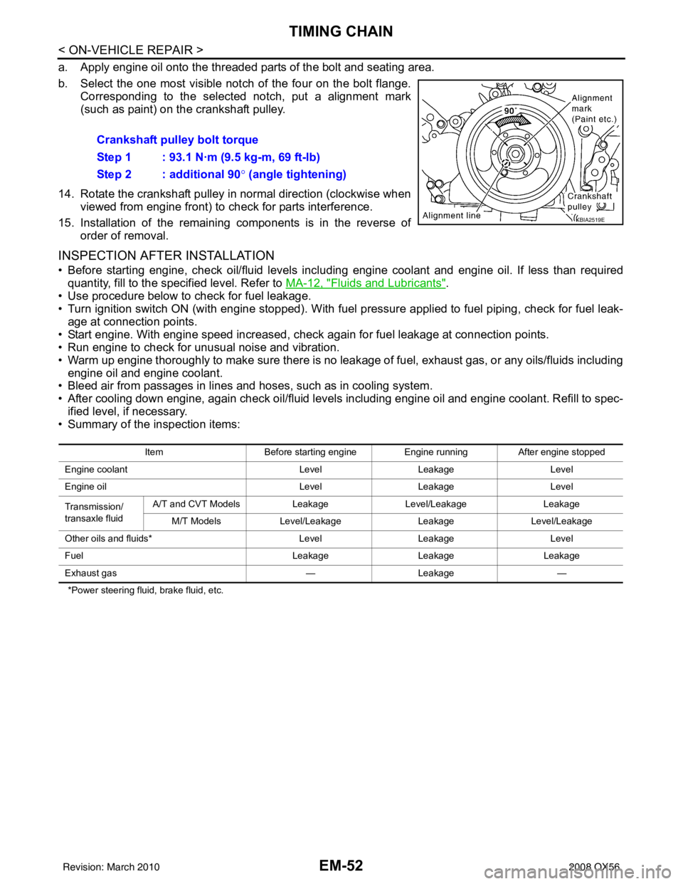
a. Apply engine oil onto the threaded parts of the bolt and seating area.
b. Select the one most visible notch of the four on the bolt flange.Corresponding to the selected notch, put a alignment mark
(such as paint) on the crankshaft pulley.
14. Rotate the crankshaft pulley in normal direction (clockwise when viewed from engine front) to check for parts interference.
15. Installation of the remaining components is in the reverse of order of removal.
INSPECTION AFTER INSTALLATION
• Before starting engine, check oil/fluid levels incl uding engine coolant and engine oil. If less than required
quantity, fill to the specified level. Refer to MA-12, "
Fluids and Lubricants".
• Use procedure below to check for fuel leakage.
• Turn ignition switch ON (with engine stopped). With fuel pressure applied to fuel piping, check for fuel leak- age at connection points.
• Start engine. With engine speed increased, che ck again for fuel leakage at connection points.
• Run engine to check for unusual noise and vibration.
• Warm up engine thoroughly to make sure there is no leakage of fuel, exhaust gas, or any oils/fluids including
engine oil and engine coolant.
• Bleed air from passages in lines and hoses, such as in cooling system.
• After cooling down engine, again check oil/fluid levels including engine oil and engine coolant. Refill to spec-
ified level, if necessary.
• Summary of the inspection items:
*Power steering fluid, brake fluid, etc.
Crankshaft pulley bolt torque
Step 1 : 93.1 N·m (9.5 kg-m, 69 ft-lb)
Step 2 : additional 90 ° (angle tightening)
KBIA2519E
Item Before starting engine Engine runningAfter engine stopped
Engine coolant LevelLeakage Level
Engine oil LevelLeakage Level
Transmission/
transaxle fluid A/T and CVT Models
LeakageLevel/Leakage Leakage
M/T Models Level/Leakage LeakageLevel/Leakage
Other oils and fluids* LevelLeakage Level
Fuel LeakageLeakage Leakage
Exhaust gas —Leakage —
Revision: March 2010 2008 QX56
Page 1873 of 4083
EM-70
< ON-VEHICLE REPAIR >
CYLINDER HEAD
*Power steering fluid, brake fluid, etc.
Disassembly and AssemblyINFOID:0000000001538829
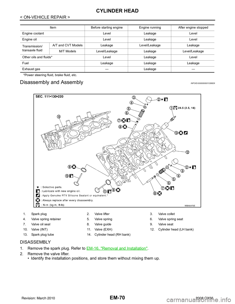
DISASSEMBLY
1. Remove the spark plug. Refer to EM-16, "Removal and Installation".
2. Remove the valve lifter. • Identify the installation positions, and store them without mixing them up.
Item Before starting engine Engine runningAfter engine stopped
Engine coolant LevelLeakage Level
Engine oil LevelLeakage Level
Transmission/
transaxle fluid A/T and CVT Models
LeakageLevel/Leakage Leakage
M/T Models Level/Leakage LeakageLevel/Leakage
Other oils and fluids* LevelLeakage Level
Fuel LeakageLeakage Leakage
Exhaust gas —Leakage —
1. Spark plug 2. Valve lifter3. Valve collet
4. Valve spring retainer 5. Valve spring6. Valve spring seat
7. Valve oil seal 8. Valve guide9. Valve seat
10. Valve (INT) 11. Valve (EXH)12. Cylinder head (LH bank)
13. Spark plug tube 14. Cylinder head (RH bank)
WBIA0470E
Revision: March 2010 2008 QX56
Page 1882 of 4083
ENGINE ASSEMBLYEM-79
< REMOVAL AND INSTALLATION >
C
DE
F
G H
I
J
K L
M A
EM
NP
O
4. Remove the engine hood. Refer to
DLK-224, "Removal and Installation of Hood Assembly".
5. Remove the cowl extension. Refer to EXT-18, "
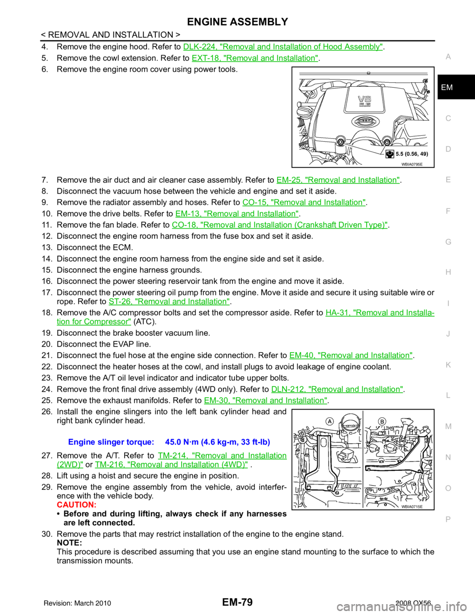
Removal and Installation".
6. Remove the engine room cover using power tools.
7. Remove the air duct and air cleaner case assembly. Refer to EM-25, "
Removal and Installation".
8. Disconnect the vacuum hose between the vehicle and engine and set it aside.
9. Remove the radiator assembly and hoses. Refer to CO-15, "
Removal and Installation".
10. Remove the drive belts. Refer to EM-13, "
Removal and Installation".
11. Remove the fan blade. Refer to CO-18, "
Removal and Installation (Crankshaft Driven Type)".
12. Disconnect the engine room harness from the fuse box and set it aside.
13. Disconnect the ECM.
14. Disconnect the engine room harness from the engine side and set it aside.
15. Disconnect the engine harness grounds.
16. Disconnect the power steering reservoir t ank from the engine and move it aside.
17. Disconnect the power steering oil pump from the engine. Move it aside and secure it using suitable wire or rope. Refer to ST-26, "
Removal and Installation".
18. Remove the A/C compressor bolts and set the compressor aside. Refer to HA-31, "
Removal and Installa-
tion for Compressor" (ATC).
19. Disconnect the brake booster vacuum line.
20. Disconnect the EVAP line.
21. Disconnect the fuel hose at the engine side connection. Refer to EM-40, "
Removal and Installation".
22. Disconnect the heater hoses at the cowl, and in stall plugs to avoid leakage of engine coolant.
23. Remove the A/T oil level indicator and indicator tube upper bolts.
24. Remove the front final drive assembly (4WD only). Refer to DLN-212, "
Removal and Installation".
25. Remove the exhaust manifolds. Refer to EM-30, "
Removal and Installation".
26. Install the engine slingers into the left bank cylinder head and right bank cylinder head.
27. Remove the A/T. Refer to TM-214, "
Removal and Installation
(2WD)" or TM-216, "Removal and Installation (4WD)" .
28. Lift using a hoist and secure the engine in position.
29. Remove the engine assembly from the vehicle, avoid interfer- ence with the vehicle body.
CAUTION:
• Before and during lifting, always check if any harnessesare left connected.
30. Remove the parts that may restrict installation of the engine to the engine stand. NOTE:
This procedure is described assuming that you use an engine stand mounting to the surface to which the
transmission mounts.
WBIA0795E
Engine slinger torque: 45.0 N·m (4.6 kg-m, 33 ft-lb)
WBIA0715E
Revision: March 2010 2008 QX56
Page 1884 of 4083
ENGINE ASSEMBLYEM-81
< REMOVAL AND INSTALLATION >
C
DE
F
G H
I
J
K L
M A
EM
NP
O
• Start engine. With engine speed increased, check again for fuel leakage at connection points.
• Run engine to check for unusual noise and vibration.
• Warm up engine thoroughly to make sure there is no leak
age of fuel, exhaust gas, or any oils/fluids including
engine oil and engine coolant.
• Bleed air from passages in lines and hoses, such as in cooling system.
• After cooling down engine, again check oil/fluid levels including engine oil and engine coolant. Refill to spec- ified level, if necessary.
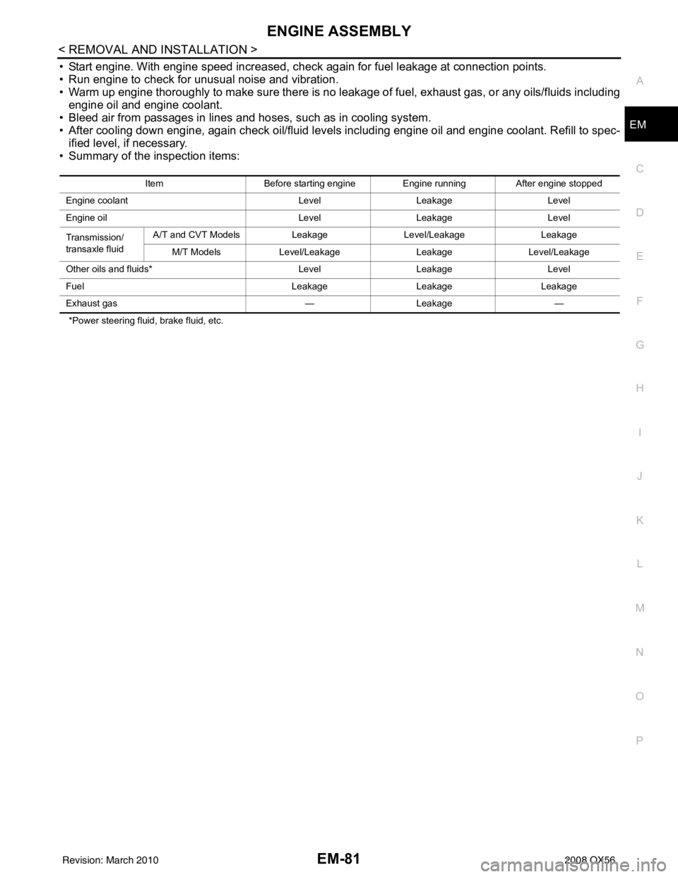
• Summary of the inspection items:
*Power steering fluid, brake fluid, etc. Item
Before starting engine Engine runningAfter engine stopped
Engine coolant LevelLeakage Level
Engine oil LevelLeakage Level
Transmission/
transaxle fluid A/T and CVT Models
LeakageLevel/Leakage Leakage
M/T Models Level/Leakage LeakageLevel/Leakage
Other oils and fluids* LevelLeakage Level
Fuel LeakageLeakageLeakage
Exhaust gas —Leakage —
Revision: March 2010 2008 QX56
Page 1937 of 4083
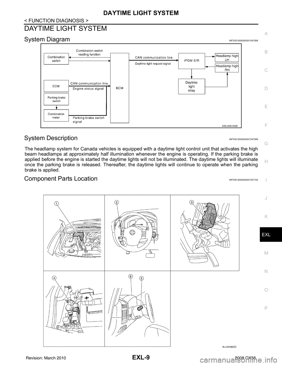
DAYTIME LIGHT SYSTEMEXL-9
< FUNCTION DIAGNOSIS >
C
DE
F
G H
I
J
K
M A
B
EXL
N
O P
DAYTIME LIGHT SYSTEM
System DiagramINFOID:0000000001547098
System DescriptionINFOID:0000000001547099
The headlamp system for Canada vehicles is equipped with a daytime light control unit that activates the high
beam headlamps at approximately half illumination whenever the engine is operating. If the parking brake is
applied before the engine is started the daytime lights will not be illuminated. The daytime lights will illuminate
once the parking brake is released. Thereafter, the daytime lights will continue to operate when the parking
brake is applied.
Component Parts LocationINFOID:0000000001547100
AWLIA0010GB
ALLIA0380ZZ
Revision: March 2010 2008 QX56
Page 1938 of 4083

EXL-10
< FUNCTION DIAGNOSIS >
DAYTIME LIGHT SYSTEM
Component Description
INFOID:0000000001547101
After starting the engine with the parking brake released and the lighting switch in the OFF or 1ST position, the
headlamp high beam automatically turns on at a reduced intensity. With the lighting switch in the 2nd position
or with autolamps ON, the headlamps function the same as conventional light systems.
OPERATION
The BCM monitors inputs from the parking brake switch and the combination switch to determine when to acti-
vate the daytime light system. The BCM sends a dayti me light request to the IPDM E/R via the CAN commu-
nication lines. The IPDM E/R grounds the daytime light relay which in turn, provides power to the ground side
of the LH high beam lamp. Power flows backward through the LH high beam lamp to the IPDM E/R, through
the high beam fuses, through the RH high beam lamp circuit to the RH high beam lamp and on to ground. The
high beam lamps are wired in series which causes them to illuminate at a reduced intensity.
1. IPDM E/R E119, E122, E123, E124 2. Parking brake switch M11 3. BCM M18, M20 (view with instrument
panel removed)
4. Daytime running light relay E103 5. Combination switch M28 6. Combination meter M24
Revision: March 2010 2008 QX56