Page 2123 of 4083

FSU-6
< SYMPTOM DIAGNOSIS >
NOISE, VIBRATION AND HARSHNESS (NVH) TROUBLESHOOTING
SYMPTOM DIAGNOSIS
NOISE, VIBRATION AND HARSHNESS (NVH) TROUBLESHOOTING
NVH Troubleshooting ChartINFOID:0000000001534620
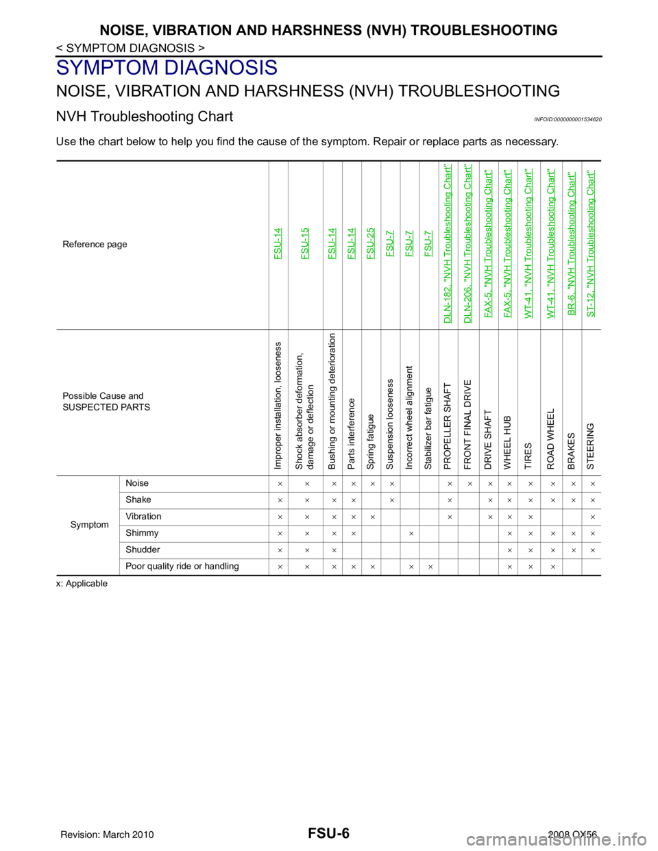
Use the chart below to help you find the cause of t he symptom. Repair or replace parts as necessary.
x: ApplicableReference page
FSU-14FSU-15FSU-14FSU-14FSU-25FSU-7FSU-7FSU-7
DLN-182, "
NVH Troubleshooting Chart
"
DLN-206, "
NVH Troubleshooting Chart
"
FAX-5, "
NVH Troubleshooting Chart
"
FAX-5, "
NVH Troubleshooting Chart
"
WT-41, "
NVH Troubleshooting Chart
"
WT-41, "
NVH Troubleshooting Chart
"
BR-6, "
NVH Troubleshooting Chart
"
ST-12, "
NVH Troubleshooting Chart
"
Possible Cause and
SUSPECTED PARTS
Improper installation, looseness
Shock absorber deformation,
damage or deflection
Bushing or mounting deterioration
Parts interference
Spring fatigue
Suspension looseness
Incorrect wheel alignment
Stabilizer bar fatigue
PROPELLER SHAFT
FRONT FINAL DRIVE
DRIVE SHAFT
WHEEL HUB
TIRES
ROAD WHEEL
BRAKES
STEERING
Symptom
Noise
× × ×××× × × ×× × × ××
Shake × × ×× × × ×× × × ××
Vibration × × ××× × ×× × ×
Shimmy × × ×× × × × × ××
Shudder ××× ×××××
Poor quality ride or handling ××××× ×× ×××
Revision: March 2010 2008 QX56
Page 2147 of 4083
HOW TO USE THIS MANUALGI-5
< HOW TO USE THIS MANUAL >
C
DE
F
G H
I
J
K L
M B
GI
N
O P
SYMBOLS
1. Union bolt 2. Copper washer3. Brake hose
4. Cap 5. Bleed valve6. Sliding pin bolt
7. Piston seal 8. Piston9. Piston boot
10. Cylinder body 11. Sliding pin12. Torque member mounting bolt
13. Washer 14. Sliding pin boot15. Bushing
16. Torque member 17. Inner shim cover18. Inner shim
19. Inner pad 20. Pad retainer21. Pad wear sensor
22. Outer pad 23. Outer shim24. Outer shim cover
1: PBC (Poly Butyl Cuprysil) grease
or silicone-based grease 2: Rubber grease
: Brake fluid
Refer to GI section for additional symbol definitions.
SFIA2959E
SAIA0749E
Revision: March 2010 2008 QX56
Page 2154 of 4083
GI-12
< HOW TO USE THIS MANUAL >
HOW TO READ WIRING DIAGRAMS
• ignition switch is “OFF”,
• doors, hood and trunk lid/back door are closed,
• pedals are not depressed, and
• parking brake is released.
MULTIPLE SWITCH
The continuity of multiple switch is described in two ways as shown below.
• The switch chart is used in schematic diagrams.
• The switch diagram is used in wiring diagrams.
SGI860
JSAIA0017GB
Revision: March 20102008 QX56
Page 2167 of 4083

PRECAUTIONSGI-25
< PRECAUTION >
C
DE
F
G H
I
J
K L
M B
GI
N
O P
2. Use the Intelligent Key or mechanical key to turn the ignition switch to the ″ACC ″ position. At this time, the
steering lock will be released.
3. Disconnect both battery cables. The steering lock will remain released and the steering wheel can be
rotated.
4. Perform the necessary repair operation.
5. When the repair work is completed, return the ignition switch to the ″LOCK ″ position before connecting
the battery cables. (At this time, the steering lock mechanism will engage.)
6. Perform a self-diagnosis check of al l control units using CONSULT-III.
Procedures without Cowl Top CoverINFOID:0000000001539208
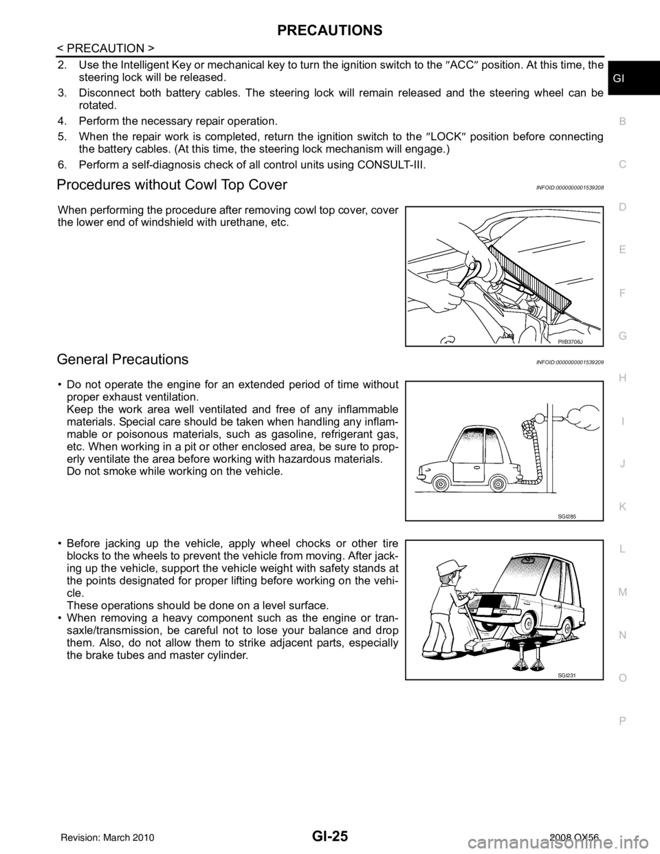
When performing the procedure after removing cowl top cover, cover
the lower end of windshield with urethane, etc.
General PrecautionsINFOID:0000000001539209
• Do not operate the engine for an extended period of time without
proper exhaust ventilation.
Keep the work area well ventilated and free of any inflammable
materials. Special care should be taken when handling any inflam-
mable or poisonous materials, such as gasoline, refrigerant gas,
etc. When working in a pit or ot her enclosed area, be sure to prop-
erly ventilate the area before working with hazardous materials.
Do not smoke while working on the vehicle.
• Before jacking up the vehicle, apply wheel chocks or other tire blocks to the wheels to prevent t he vehicle from moving. After jack-
ing up the vehicle, support the vehicle weight with safety stands at
the points designated for proper lifting before working on the vehi-
cle.
These operations should be done on a level surface.
• When removing a heavy component such as the engine or tran-
saxle/transmission, be careful not to lose your balance and drop
them. Also, do not allow them to strike adjacent parts, especially
the brake tubes and master cylinder.
PIIB3706J
SGI285
SGI231
Revision: March 2010 2008 QX56
Page 2173 of 4083
LIFTING POINTGI-31
< PRECAUTION >
C
DE
F
G H
I
J
K L
M B
GI
N
O P
• When setting the lift arm, do not allow the arm to contact the brake tubes, brake cable, or fuel lines.
WAIA0029E
Revision: March 2010 2008 QX56
Page 2175 of 4083
TOW TRUCK TOWINGGI-33
< PRECAUTION >
C
DE
F
G H
I
J
K L
M B
GI
N
O P
Never tow the vehicle using only the towing points. To avoid
damaging the vehicle body, use propeer towing equipment
when towing.
Vehicle Recovery (Freeing a stuck vehicle)INFOID:0000000004900864
• Tow chains or cables must be attached only to the main structural members of the vehicle.
• Pulling devices should be routed so they do not touch any part of the suspension, steering, brake or
cooling systems
• Always pull the cable straight out from the front or rear of the vehicle. Never pull the vehicle at a
sideways angle.
• Pulling devices such as ropes or canvas straps are not recommended for use for vehicle towing or
recovery.
WAIA0055E
Revision: March 2010 2008 QX56
Page 2539 of 4083
![INFINITI QX56 2008 Factory Service Manual LAN-44
< FUNCTION DIAGNOSIS >[CAN]
CAN COMMUNICATION SYSTEM
FUNCTION DIAGNOSIS
CAN COMMUNICATION SYSTEM
CAN System Specification ChartINFOID:0000000001282400
Determine CAN system type from the followi INFINITI QX56 2008 Factory Service Manual LAN-44
< FUNCTION DIAGNOSIS >[CAN]
CAN COMMUNICATION SYSTEM
FUNCTION DIAGNOSIS
CAN COMMUNICATION SYSTEM
CAN System Specification ChartINFOID:0000000001282400
Determine CAN system type from the followi](/manual-img/42/57030/w960_57030-2538.png)
LAN-44
< FUNCTION DIAGNOSIS >[CAN]
CAN COMMUNICATION SYSTEM
FUNCTION DIAGNOSIS
CAN COMMUNICATION SYSTEM
CAN System Specification ChartINFOID:0000000001282400
Determine CAN system type from the following specificat
ion chart. Then choose the correct diagnosis sheet.
NOTE:
Refer to LAN-14, "
Trouble Diagnosis Procedure" for how to use CAN system specification chart.
×: Applicable
VEHICLE EQUIPMENT IDENTIFICATION INFORMATION
NOTE:
Check CAN system type from the vehicle shape and equipment.
CAN Communication Signal ChartINFOID:0000000001282401
Refer to LAN-13, "How to Use CAN Communication Signal Chart" for how to use CAN communication signal
chart.
NOTE:
Refer to LAN-36, "
Abbreviation List" for the abbreviations of the connecting units.
T: Transmit R: Receive
Body type Wagon
Axle 2WD4WD
Engine VK56DE
Transmission A/T
Brake control VDC
ICC system ××
CAN system type 1234
Diagnosis sheet LAN-40
LAN-41LAN-42LAN-43
AWMIA0012GB
Signal name/Connecting unitECM
TCM
LASER ICC
ADP
AV
BCM
HVAC I-KEY M&A
STRG 4WDABS
IPDM-E
Accelerator pedal position signal T RR R R
A/C compressor request signal T R
ASCD CRUISE lamp signal T R
ASCD OD cancel request signal T R
ASCD operation signal T R
ASCD SET lamp signal T R
Battery voltage signal T R
Closed throttle position signal T RR
Cooling fan speed request signal T R
Engine coolant temperature signal T RR
Revision: March 2010 2008 QX56
Page 2541 of 4083
![INFINITI QX56 2008 Factory Service Manual LAN-46
< FUNCTION DIAGNOSIS >[CAN]
CAN COMMUNICATION SYSTEM
NOTE:
CAN data of the air bag diagnosis sensor unit is not us
ed by usual service work, thus it is omitted.
Tire pressure data signal R T
T INFINITI QX56 2008 Factory Service Manual LAN-46
< FUNCTION DIAGNOSIS >[CAN]
CAN COMMUNICATION SYSTEM
NOTE:
CAN data of the air bag diagnosis sensor unit is not us
ed by usual service work, thus it is omitted.
Tire pressure data signal R T
T](/manual-img/42/57030/w960_57030-2540.png)
LAN-46
< FUNCTION DIAGNOSIS >[CAN]
CAN COMMUNICATION SYSTEM
NOTE:
CAN data of the air bag diagnosis sensor unit is not us
ed by usual service work, thus it is omitted.
Tire pressure data signal R T
Tire pressure signal R TR
Turn indicator signal TR
Buzzer output signal TR
Door lock/unlock request signal RT
Hazard request signal RT
Hazard warning lamp request signal RT
Ignition knob switch signal RT
KEY warning signal TR
LOCK warning signal TR
Panic alarm request signal RT
Power window open request signal RT
1st position switch signal R T
4th position switch signal R T
Distance to empty signal RT
Fuel level low warning signal RT
Fuel level sensor signal R T
Parking brake switch signal RT
Seat belt buckle switch signal RT
Stop lamp switch signal R T
Tow mode switch signal R T
Vehicle speed signal RRR RRR R T
RRRT
Steering angle sensor signal TR
ABS malfunction signal RT
ABS warning lamp signal RT
Brake pressure sensor signal RT
Brake warning lamp signal RT
SLIP indicator lamp signal RT
TCS malfunction signal RT
VDC malfunction signal RT
VDC OFF indicator lamp signal RRT
VDC operation signal RT
Front wiper stop position signal RT
High beam status signal R T
Hood switch signal RT
Low beam status signal R T
Rear window defogger control signal R RT
Ambient sensor signal RT
Signal name/Connecting unit
ECM
TCM
LASER ICC
ADP
AV
BCM
HVAC I-KEY M&A
STRG 4WDABS
IPDM-E
Revision: March 2010 2008 QX56