Page 1948 of 4083
EXL-20
< FUNCTION DIAGNOSIS >
TRAILER TOW
TRAILER TOW
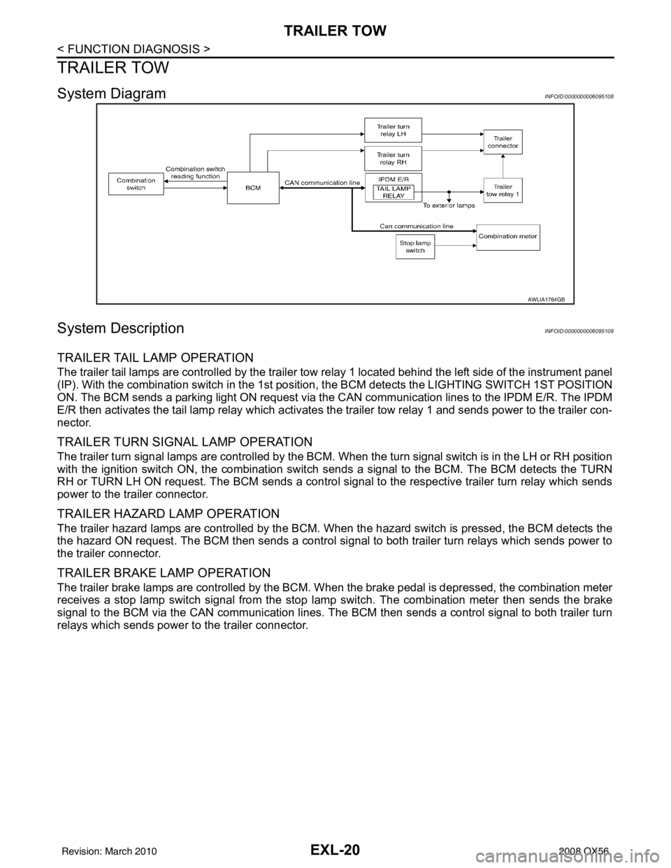
System DiagramINFOID:0000000006095108
System DescriptionINFOID:0000000006095109
TRAILER TAIL LAMP OPERATION
The trailer tail lamps are controlled by the trailer tow relay 1 located behind the left side of the instrument panel
(IP). With the combination switch in the 1st position, the BCM detects the LIGHTING SWITCH 1ST POSITION
ON. The BCM sends a parking light ON request via the CAN communication lines to the IPDM E/R. The IPDM
E/R then activates the tail lamp relay which activates the trailer tow relay 1 and sends power to the trailer con-
nector.
TRAILER TURN SIGNAL LAMP OPERATION
The trailer turn signal lamps are controlled by the BCM. When the turn signal switch is in the LH or RH position
with the ignition switch ON, the combination switch sends a signal to the BCM. The BCM detects the TURN
RH or TURN LH ON request. The BCM sends a control signal to the respective trailer turn relay which sends
power to the trailer connector.
TRAILER HAZARD LAMP OPERATION
The trailer hazard lamps are controlled by the BCM. W hen the hazard switch is pressed, the BCM detects the
the hazard ON request. The BCM then sends a control si gnal to both trailer turn relays which sends power to
the trailer connector.
TRAILER BRAKE LAMP OPERATION
The trailer brake lamps are controlled by the BCM. When the brake pedal is depressed, the combination meter
receives a stop lamp switch signal from the stop lamp switch. The combination meter then sends the brake
signal to the BCM via the CAN communication lines. The BCM then sends a control signal to both trailer turn
relays which sends power to the trailer connector.
AWLIA1764GB
Revision: March 2010 2008 QX56
Page 1949 of 4083
TRAILER TOWEXL-21
< FUNCTION DIAGNOSIS >
C
DE
F
G H
I
J
K
M A
B
EXL
N
O P
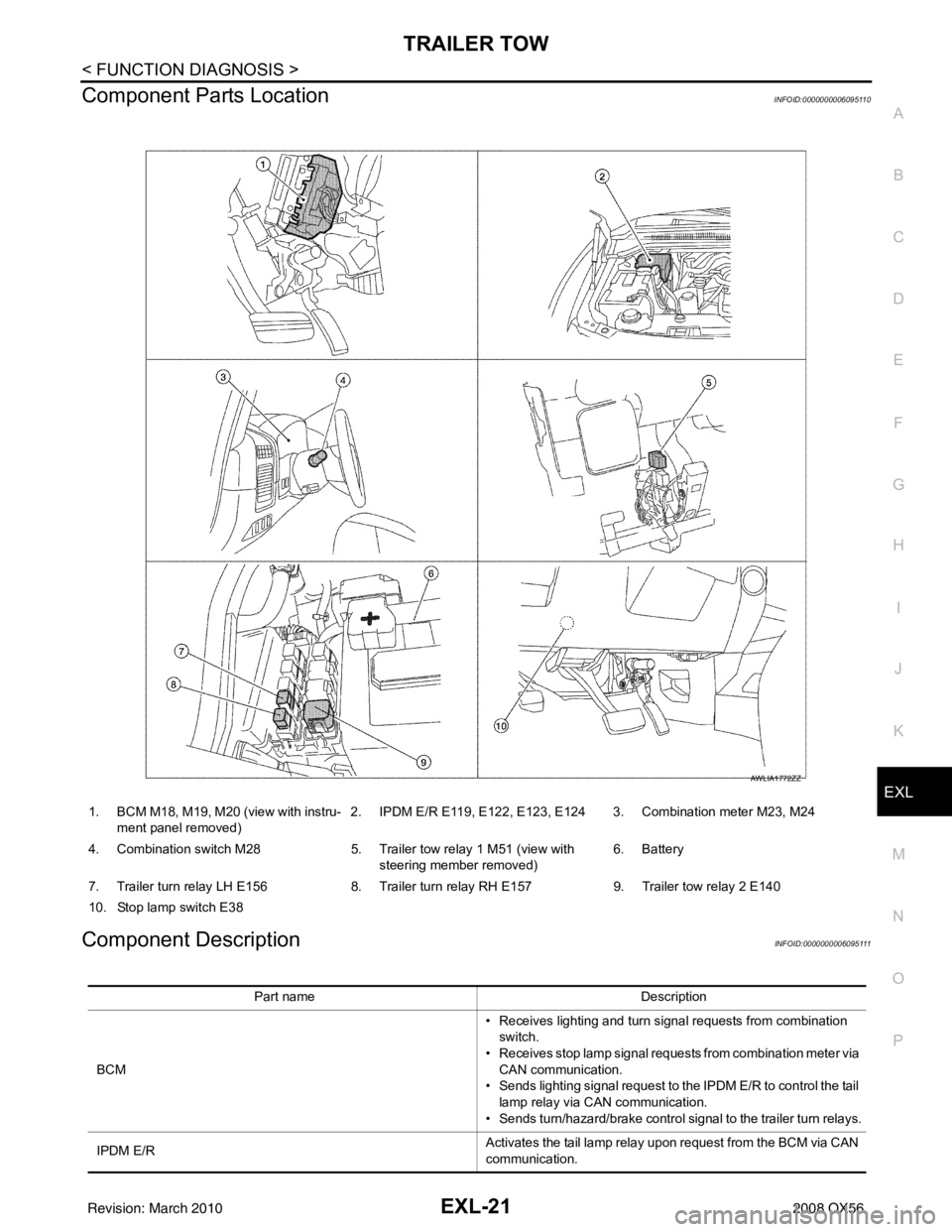
Component Parts LocationINFOID:0000000006095110
Component DescriptionINFOID:0000000006095111
1. BCM M18, M19, M20 (view with instru- ment panel removed) 2. IPDM E/R E119, E122, E123, E124 3. Combination meter M23, M24
4. Combination switch M28 5. Trailer tow relay 1 M51 (view with
steering member removed) 6. Battery
7. Trailer turn relay LH E156 8. Trailer turn relay RH E157 9. Trailer tow relay 2 E140
10. Stop lamp switch E38
AWLIA1772ZZ
Part name Description
BCM • Receives lighting and turn signal requests from combination
switch.
• Receives stop lamp signal requests from combination meter via CAN communication.
• Sends lighting signal request to the IPDM E/R to control the tail
lamp relay via CAN communication.
• Sends turn/hazard/brake control signal to the trailer turn relays.
IPDM E/R Activates the tail lamp relay upon request from the BCM via CAN
communication.
Revision: March 2010
2008 QX56
Page 1953 of 4083
DIAGNOSIS SYSTEM (BCM)EXL-25
< FUNCTION DIAGNOSIS >
C
DE
F
G H
I
J
K
M A
B
EXL
N
O P
1: The item is indicated, not monitored.
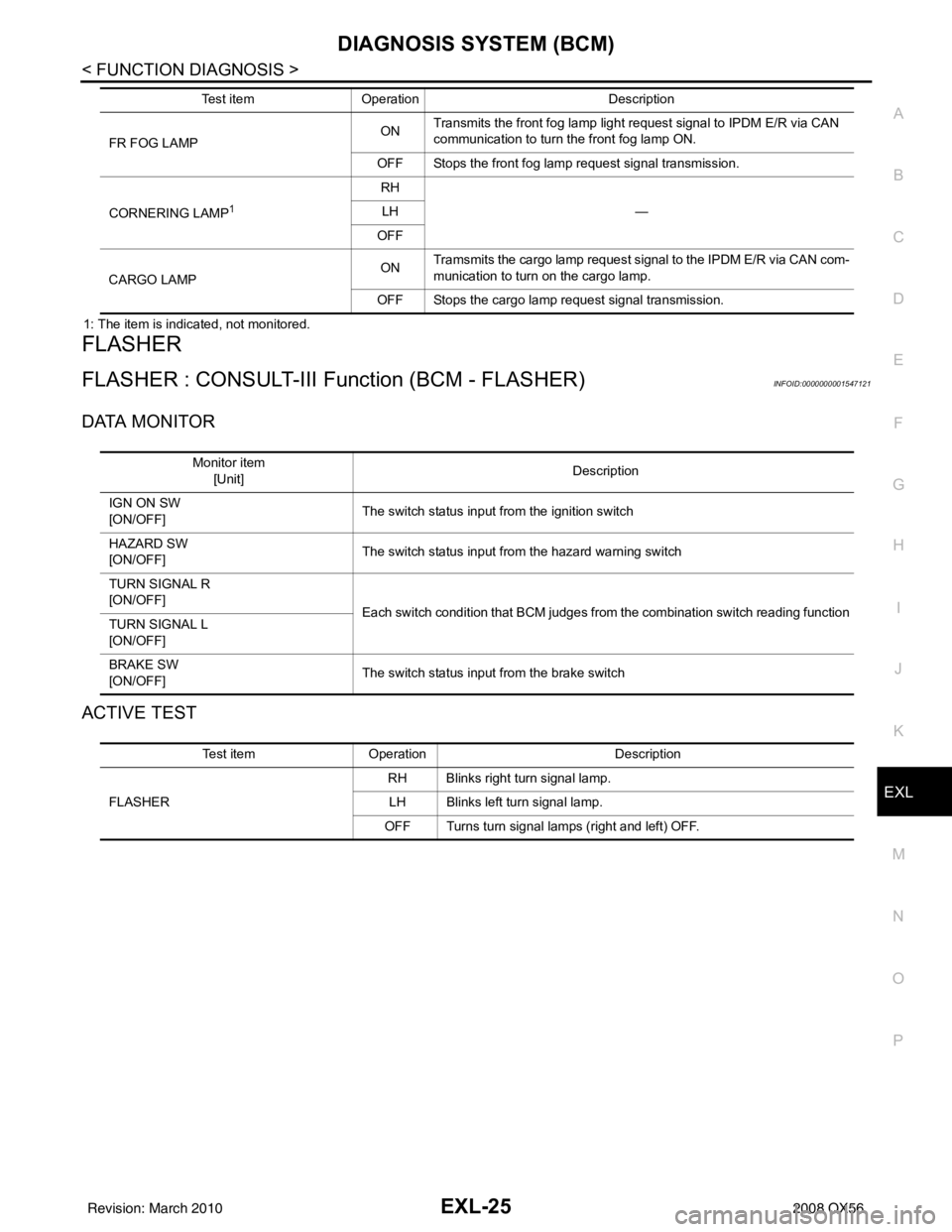
FLASHER
FLASHER : CONSULT-III Function (BCM - FLASHER)INFOID:0000000001547121
DATA MONITOR
ACTIVE TEST
FR FOG LAMP ON
Transmits the front fog lamp light request signal to IPDM E/R via CAN
communication to turn the front fog lamp ON.
OFF Stops the front fog lamp request signal transmission.
CORNERING LAMP
1
RH —
LH
OFF
CARGO LAMP ON
Tramsmits the cargo lamp request signal to the IPDM E/R via CAN com-
munication to turn on the cargo lamp.
OFF Stops the cargo lamp request signal transmission.
Test item
Operation Description
Monitor item
[Unit] Description
IGN ON SW
[ON/OFF] The switch status input from the ignition switch
HAZARD SW
[ON/OFF] The switch status input from the hazard warning switch
TURN SIGNAL R
[ON/OFF] Each switch condition that BCM judges from the combination switch reading function
TURN SIGNAL L
[ON/OFF]
BRAKE SW
[ON/OFF] The switch status input from the brake switch
Test item
Operation Description
FLASHER RH Blinks right turn signal lamp.
LH Blinks left turn signal lamp.
OFF Turns turn signal lamps (right and left) OFF.
Revision: March 2010 2008 QX56
Page 2030 of 4083
EXL-102
< SYMPTOM DIAGNOSIS >
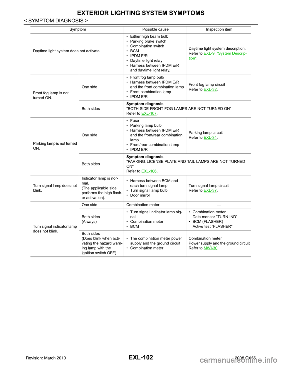
EXTERIOR LIGHTING SYSTEM SYMPTOMS
Daytime light system does not activate.• Either high beam bulb
• Parking brake switch
• Combination switch
•BCM
• IPDM E/R
• Daytime light relay
• Harness between IPDM E/R
and daytime light relay. Daytime light system description.
Refer to EXL-9, "System Descrip-
tion".
Front fog lamp is not
turned ON. One side
• Front fog lamp bulb
• Harness between IPDM E/R
and the front combination lamp
• Front combination lamp
• IPDM E/R Front fog lamp circuit
Refer to EXL-32
.
Both sides Symptom diagnosis
"BOTH SIDE FRONT FOG LAMPS ARE NOT TURNED ON"
Refer to
EXL-107
.
Parking lamp is not turned
ON. One side•Fuse
• Parking lamp bulb
• Harness between IPDM E/R
and the front/rear combination
lamp
• Front/rear combination lamp
• IPDM E/R Parking lamp
circuit
Refer to EXL-34
.
Both sides Symptom diagnosis
"PARKING, LICENSE PLATE AND TAIL LAMPS ARE NOT TURNED
ON"
Refer to
EXL-106
.
Turn signal lamp does not
blink. Indicator lamp is nor-
mal.
(The applicable side
performs the high flash-
er activation).• Harness between BCM and
each turn signal lamp
• Turn signal lamp bulb
• Door mirror Turn signal lamp circuit
Refer to EXL-37
.
Turn signal indicator lamp
does not blink. One side
Combination meter —
Both sides
(Always) • Turn signal indicator lamp sig-
nal
• Combination meter
•BCM • Combination meter.
Data monitor "TURN IND"
•BCM (FLASHER)
Active test "FLASHER"
Both sides
(Does blink when acti-
vating the hazard warn-
ing lamp with the
ignition switch OFF) • The combination meter power
supply and the ground circuit
• Combination meter Combination meter
Power supply and the ground circuit
Refer to MWI-30
.
Symptom
Possible causeInspection item
Revision: March 2010 2008 QX56
Page 2089 of 4083
NOISE, VIBRATION AND HARSHNESS (NVH) TROUBLESHOOTINGFAX-5
< SYMPTOM DIAGNOSIS >
CEF
G H
I
J
K L
M A
B
FA X
N
O P
SYMPTOM DIAGNOSIS
NOISE, VIBRATION AND HARSHN ESS (NVH) TROUBLESHOOTING
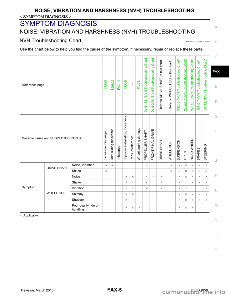
NVH Troubleshooting ChartINFOID:0000000001534449
Use the chart below to help you find t he cause of the symptom. If necessary, repair or replace these parts.
×: ApplicableReference page
FA X - 9FA X - 11FA X - 11FA X - 9—
FA X - 6
DLN-182, "
NVH Troubleshooting Chart
"
DLN-206, "
NVH Troubleshooting Chart
"
Refer to DRIVE SHAFT in this chart.
Refer to WHEEL HUB in this chart.
FSU-6, "
NVH Troubleshooting Chart
"
WT-41, "
NVH Troubleshooting Chart
"
WT-41, "
NVH Troubleshooting Chart
"
BR-6, "
NVH Troubleshooting Chart
"
ST-12, "
NVH Troubleshooting Chart
"
Possible cause and SUSPECTED PARTS
Excessive joint angle
Joint sliding resistance
Imbalance
Improper installation, looseness
Parts interference
Wheel bearing damage
PROPELLER SHAFT
FRONT FINAL DRIVE
DRIVE SHAFT
WHEEL HUB
SUSPENSION
TIRES
ROAD WHEEL
BRAKES
STEERING
Symptom DRIVE SHAFT
Noise, Vibration
×× × × × ×××× ×
Shake × × ×× ×××× ×
WHEEL HUB Noise
×× × × × ×××× ×
Shake ×× × × ×××× ×
Vibration ×× × × ×× ×
Shimmy ×××××× ×
Shudder ×× ××× ×
Poor quality ride or
handling ×××
×××
Revision: March 2010 2008 QX56
Page 2091 of 4083
WHEEL HUBFAX-7
< REMOVAL AND INSTALLATION >
CEF
G H
I
J
K L
M A
B
FA X
N
O P
REMOVAL AND INSTALLATION
WHEEL HUB
Removal and InstallationINFOID:0000000001534453
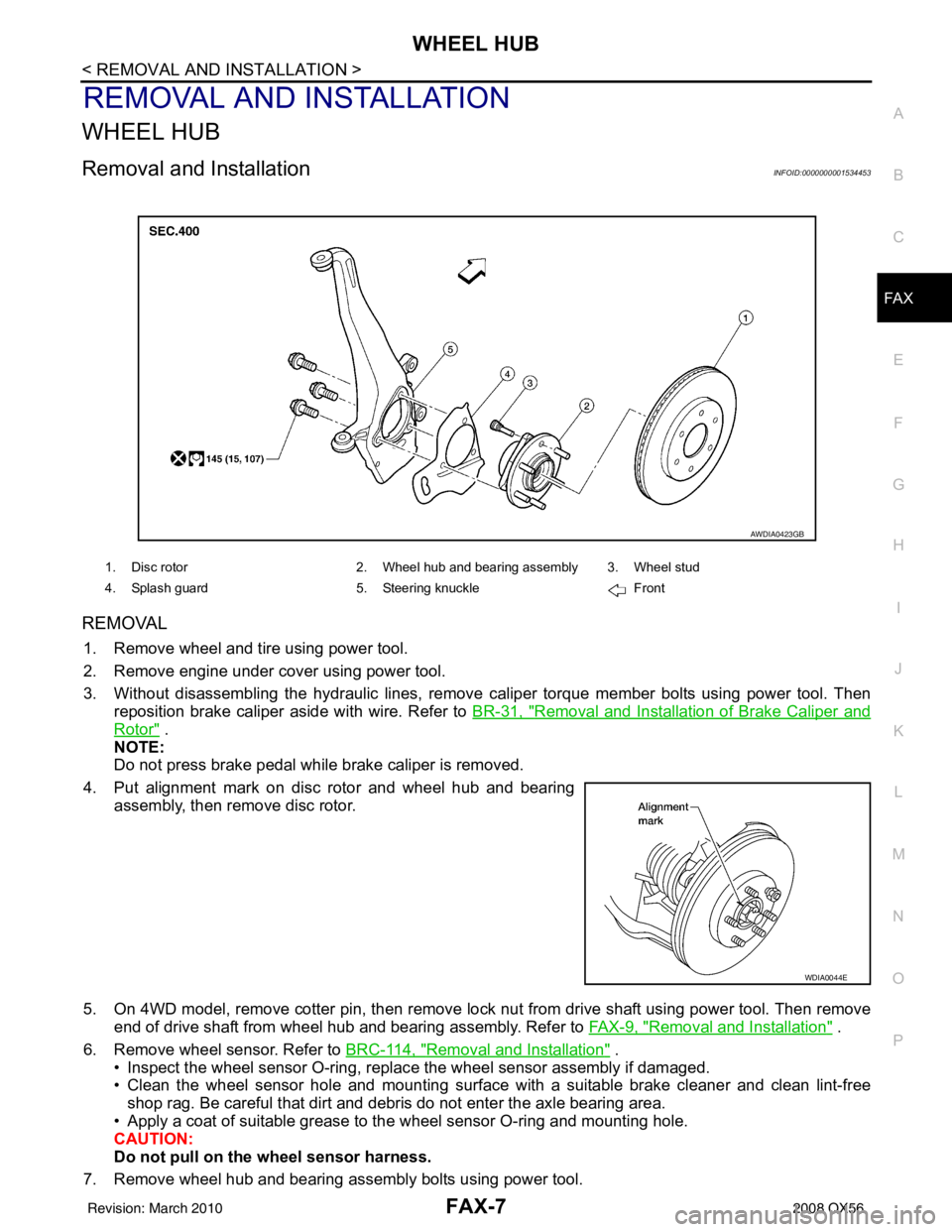
REMOVAL
1. Remove wheel and tire using power tool.
2. Remove engine under cover using power tool.
3. Without disassembling the hydraulic lines, remove caliper torque member bolts using power tool. Then
reposition brake caliper aside with wire. Refer to BR-31, "
Removal and Installation of Brake Caliper and
Rotor" .
NOTE:
Do not press brake pedal while brake caliper is removed.
4. Put alignment mark on disc rotor and wheel hub and bearing assembly, then remove disc rotor.
5. On 4WD model, remove cotter pin, then remove lock nut from drive shaft using power tool. Then remove end of drive shaft from wheel hub and bearing assembly. Refer to FAX-9, "
Removal and Installation" .
6. Remove wheel sensor. Refer to BRC-114, "
Removal and Installation" .
• Inspect the wheel sensor O-ring, replac e the wheel sensor assembly if damaged.
• Clean the wheel sensor hole and mounting surface with a suitable brake cleaner and clean lint-free shop rag. Be careful that dirt and debris do not enter the axle bearing area.
• Apply a coat of suitable grease to the wheel sensor O-ring and mounting hole.
CAUTION:
Do not pull on the wheel sensor harness.
7. Remove wheel hub and bearing assembly bolts using power tool.
1. Disc rotor 2. Wheel hub and bearing assembly 3. Wheel stud
4. Splash guard 5. Steering knuckle Front
AWDIA0423GB
WDIA0044E
Revision: March 2010 2008 QX56
Page 2092 of 4083
FAX-8
< REMOVAL AND INSTALLATION >
WHEEL HUB
8. Remove splash guard and wheel hub and bearing assembly from steering knuckle.
INSPECTION AFTER REMOVAL
Check for deformity, cracks and damage on each part, replace if necessary.
INSTALLATION
Installation is in the reverse order of removal.
• Use new bolts when installing the wheel hub and bearing assembly.
• When installing disc rotor on wheel hub and bearing assembly,
position the disc rotor according to alignment mark.
(When not using the alignment mark, refer to BR-31, "
Removal
and Installation of Brake Caliper and Rotor" .)
• When installing wheel and tire. Refer to WT-48, "
Rotation" .
WDIA0044E
Revision: March 2010 2008 QX56
Page 2093 of 4083
DRIVE SHAFTFAX-9
< REMOVAL AND INSTALLATION >
CEF
G H
I
J
K L
M A
B
FA X
N
O P
DRIVE SHAFT
Removal and InstallationINFOID:0000000001534458
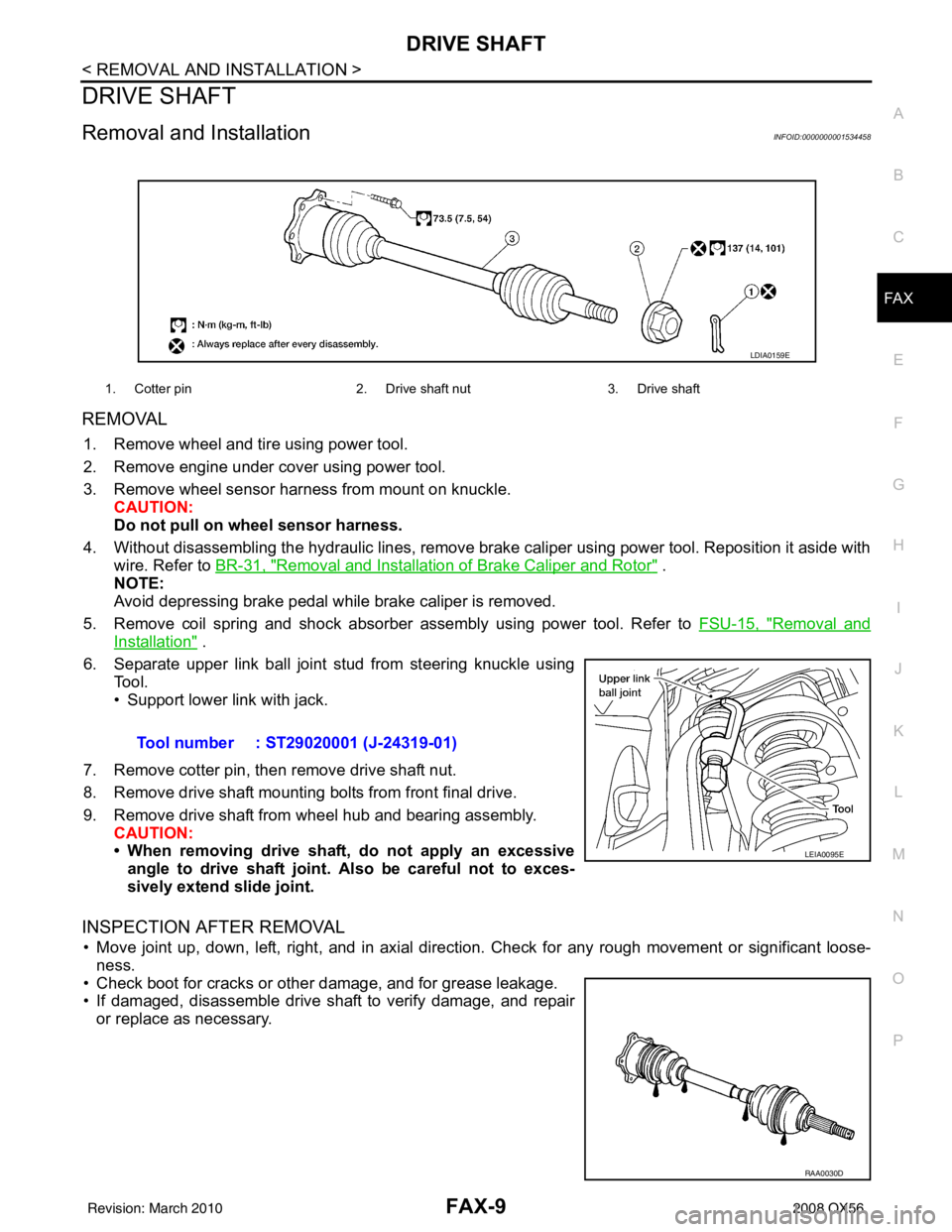
REMOVAL
1. Remove wheel and tire using power tool.
2. Remove engine under cover using power tool.
3. Remove wheel sensor harness from mount on knuckle. CAUTION:
Do not pull on wheel sensor harness.
4. Without disassembling the hydraulic lines, remove brake caliper using power tool. Reposition it aside with wire. Refer to BR-31, "
Removal and Installation of Brake Caliper and Rotor" .
NOTE:
Avoid depressing brake pedal while brake caliper is removed.
5. Remove coil spring and shock absorber assembly using power tool. Refer to FSU-15, "
Removal and
Installation" .
6. Separate upper link ball joint stud from steering knuckle using Tool.
• Support lower link with jack.
7. Remove cotter pin, then remove drive shaft nut.
8. Remove drive shaft mounting bolts from front final drive.
9. Remove drive shaft from wheel hub and bearing assembly. CAUTION:
• When removing drive shaf t, do not apply an excessive
angle to drive shaft joint. Also be careful not to exces-
sively extend slide joint.
INSPECTION AFTER REMOVAL
• Move joint up, down, left, right, and in axial directi on. Check for any rough movement or significant loose-
ness.
• Check boot for cracks or other damage, and for grease leakage.
• If damaged, disassemble drive shaft to verify damage, and repair or replace as necessary.
1. Cotter pin 2. Drive shaft nut3. Drive shaft
LDIA0159E
Tool number : ST29020001 (J-24319-01)
LEIA0095E
RAA0030D
Revision: March 2010 2008 QX56