2008 INFINITI QX56 engine oil
[x] Cancel search: engine oilPage 3574 of 4083

A/T CONTROL SYSTEMTM-27
< FUNCTION DIAGNOSIS >
CEF
G H
I
J
K L
M A
B
TM
N
O P
FUNCTION OF PRESSURE SWITCH
Pilot valve A Adjusts the line pressure and produces the constant pressure (pilot pressure) required
for line pressure control, shift change control, and lock-up control.
Pilot valve B Adjusts the line pressure and produces the constant pressure (pilot pressure) required
for shift change control.
Low coast brake switching valve During engine braking, supplies the line pressure to the low coast brake reducing valve.
Low coast brake reducing valve When the low coast brake is coupled, adjusts the line pressure to the optimum pressure
(low coast brake pressure) and supplies it to the low coast brake.
N-R accumulator Produces the stabilizing pressure for when N-R is selected.
Direct clutch piston switching valve Operates in 4GR gear and switches the direct clutch coupling capacity.
High and low reverse clutch control valve When the high and low reverse clutch is coupled, adjusts the line pressure to the opti-
mum pressure (high and low reverse clutch pressure) and supplies it to the high and low
reverse clutch. (In 1GR, 3GR, 4GR and 5GR, adjusts the clutch pressure.)
Input clutch control valve When the input clutch is coupled, adjusts the line pressure to the optimum pressure (in-
put clutch pressure) and supplies it to the input clutch. (In 4GR and 5GR, adjusts the
clutch pressure.)
Direct clutch control valve When the direct clutch is coupled, adjusts the line pressure to the optimum pressure (di-
rect clutch pressure) and supplies it to the direct clutch. (In 2GR, 3GR, and 4GR, adjusts
the clutch pressure.)
TCC control valve
TCC control plug
TCC control sleeve Switches the lock-up to operating or released. Also, by performing the lock-up operation
transiently, lock-up smoothly.
Torque converter lubrication valve Operates during lock-up to switch the torque converter, cooling, and lubrication system
oil path.
Cool bypass valve Allows excess oil to bypass cooler circuit without being fed into it.
Line pressure relief valve Discharges excess oil from line pressure circuit.
N-D accumulator Produces the stabilizing pressure for when N-D is selected.
Manual valve Sends line pressure to each circuit according to the select position. The circuits to which
the line pressure is not sent drain.
Name
Function
Name Function
Pressure switch 2 (LC/B) Detects any malfunction in the low coast brake hydraulic pressure. When it detects any
malfunction, it puts the system into fail-safe mode.
Revision: March 2010
2008 QX56
Page 3614 of 4083
P0745 PRESSURE CONTROL SOLENOID ATM-67
< COMPONENT DIAGNOSIS >
CEF
G H
I
J
K L
M A
B
TM
N
O P
P0745 PRESSURE CONTROL SOLENOID A
DescriptionINFOID:0000000001604087
The line pressure solenoid valve regulates the oil pum p discharge pressure to suit the driving condition in
response to a signal sent from the TCM.
The line pressure duty cycle value is not consistent when the closed throttle position signal is “ON”.
To confirm the line pressure duty cycle at low pressu re, the accelerator (throttle) should be open until
the closed throttle posi tion signal is “OFF”.
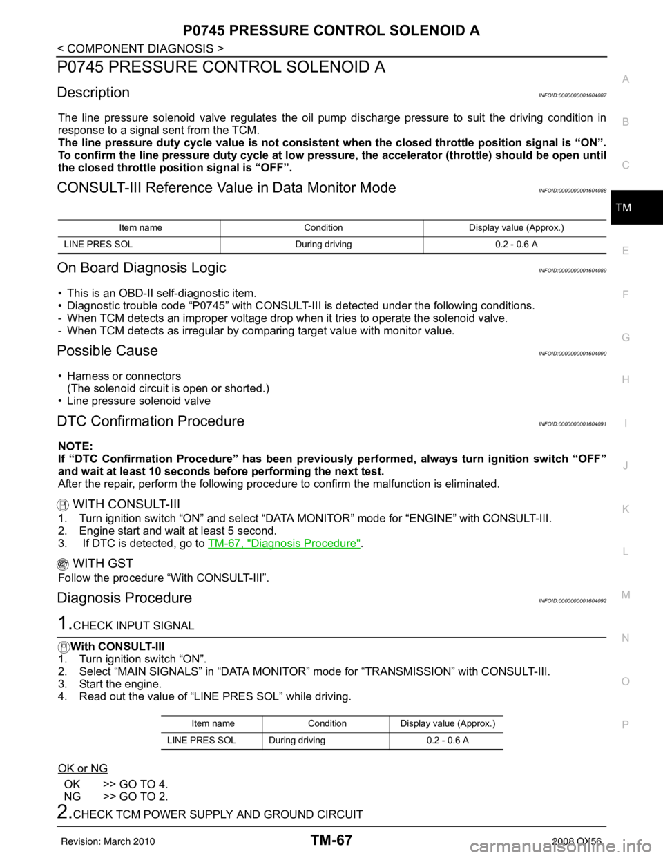
CONSULT-III Reference Val ue in Data Monitor ModeINFOID:0000000001604088
On Board Diagnosis LogicINFOID:0000000001604089
• This is an OBD-II self-diagnostic item.
• Diagnostic trouble code “P0745” with CONSULT-III is detected under the following conditions.
- When TCM detects an improper voltage drop when it tries to operate the solenoid valve.
- When TCM detects as irregular by comparing target value with monitor value.
Possible CauseINFOID:0000000001604090
• Harness or connectors
(The solenoid circuit is open or shorted.)
• Line pressure solenoid valve
DTC Confirmation ProcedureINFOID:0000000001604091
NOTE:
If “DTC Confirmation Procedure” has been previously performed, always turn ignition switch “OFF”
and wait at least 10 seconds before performing the next test.
After the repair, perform the following procedure to confirm the malfunction is eliminated.
WITH CONSULT-III
1. Turn ignition switch “ON” and select “DATA MONITOR” mode for “ENGINE” with CONSULT-III.
2. Engine start and wait at least 5 second.
3. If DTC is detected, go to TM-67, "
Diagnosis Procedure".
WITH GST
Follow the procedure “With CONSULT-III”.
Diagnosis ProcedureINFOID:0000000001604092
1.CHECK INPUT SIGNAL
With CONSULT-III
1. Turn ignition switch “ON”.
2. Select “MAIN SIGNALS” in “DATA MONITOR” mode for “TRANSMISSION” with CONSULT-III.
3. Start the engine.
4. Read out the value of “LINE PRES SOL” while driving.
OK or NG
OK >> GO TO 4.
NG >> GO TO 2.
2.CHECK TCM POWER SUPPLY AND GROUND CIRCUIT
Item name Condition Display value (Approx.)
LINE PRES SOL During driving0.2 - 0.6 A
Item nameCondition Display value (Approx.)
LINE PRES SOL During driving 0.2 - 0.6 A
Revision: March 2010 2008 QX56
Page 3671 of 4083
TM-124
< SYMPTOM DIAGNOSIS >
SYSTEM SYMPTOM
Refer to TM-185, "Inspection and Judgment".
OK or NG
OK >> GO TO 6.
OK in “1” position, NG in “R” position>>GO TO 5.
NG in both “1” and “R” positions>>GO TO 8.
5.DETECT MALFUNCTIONING ITEM
1. Disassemble A/T. Refer to TM-232, "
Disassembly".
2. Check the following items:
- Reverse brake. Refer to TM-232, "
Disassembly".
OK or NG
OK >> GO TO 9.
NG >> Repair or replace damaged parts.
6.CHECK LINE PRESSURE
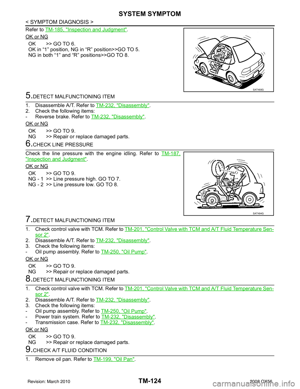
Check the line pressure with the engine idling. Refer to TM-187,
"Inspection and Judgment".
OK or NG
OK >> GO TO 9.
NG - 1 >> Line pressure high. GO TO 7.
NG - 2 >> Line pressure low. GO TO 8.
7.DETECT MALFUNCTIONING ITEM
1. Check control valve with TCM. Refer to TM-201, "
Control Valve with TCM and A/T Fluid Temperature Sen-
sor 2".
2. Disassemble A/T. Refer to TM-232, "
Disassembly".
3. Check the following items:
- Oil pump assembly. Refer to TM-250, "
Oil Pump".
OK or NG
OK >> GO TO 9.
NG >> Repair or replace damaged parts.
8.DETECT MALFUNCTIONING ITEM
1. Check control valve with TCM. Refer to TM-201, "
Control Valve with TCM and A/T Fluid Temperature Sen-
sor 2".
2. Disassemble A/T. Refer to TM-232, "
Disassembly".
3. Check the following items:
- Oil pump assembly. Refer to TM-250, "
Oil Pump".
- Power train system. Refer to TM-232, "
Disassembly".
- Transmission case. Refer to TM-232, "
Disassembly".
OK or NG
OK >> GO TO 9.
NG >> Repair or replace damaged parts.
9.CHECK A/T FLUID CONDITION
1. Remove oil pan. Refer to TM-199, "
Oil Pan".
SAT493G
SAT494G
Revision: March 2010 2008 QX56
Page 3675 of 4083
TM-128
< SYMPTOM DIAGNOSIS >
SYSTEM SYMPTOM
Vehicle Cannot Be Started from D1
INFOID:0000000001604186
SYMPTOM:
Vehicle cannot be started from D1 on cruise test - Part 1.
DIAGNOSTIC PROCEDURE
1.CONFIRM THE SYMPTOM
Check if vehicle creeps in “R” position.
OK or NG
OK >> GO TO 2.
NG >> Refer to TM-123, "
Vehicle Does Not Creep Backward in "R" Position".
2.CHECK SELF-DIAGNOSTIC RESULTS
Perform self-diagnosis. Refer to TM-32, "
CONSULT-III Functi on (TRANSMISSION)".
Is any malfunction detected by self-diagnostic results?
YES >> Check the malfunctioning system.
NO >> GO TO 3.
3.CHECK ACCELERATOR PEDAL POSITION(APP) SENSOR
Check accelerator pedal position (APP) sensor. Refer to TM-69, "
Diagnosis Procedure".
OK or NG
OK >> GO TO 4.
NG >> Repair or replace accelera tor pedal position (APP) sensor.
4.CHECK A/T FLUID LEVEL
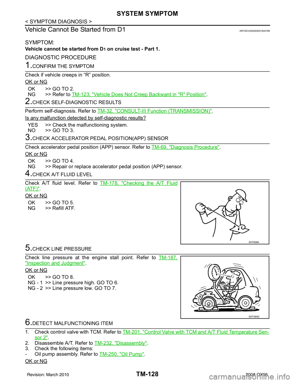
Check A/T fluid level. Refer to TM-178, "
Checking the A/T Fluid
(ATF)".
OK or NG
OK >> GO TO 5.
NG >> Refill ATF.
5.CHECK LINE PRESSURE
Check line pressure at the engine stall point. Refer to TM-187,
"Inspection and Judgment".
OK or NG
OK >> GO TO 8.
NG - 1 >> Line pressure high. GO TO 6.
NG - 2 >> Line pressure low. GO TO 7.
6.DETECT MALFUNCTIONING ITEM
1. Check control valve with TCM. Refer to TM-201, "
Control Valve with TCM and A/T Fluid Temperature Sen-
sor 2".
2. Disassemble A/T. Refer to TM-232, "
Disassembly".
3. Check the following items:
- Oil pump assembly. Refer to TM-250, "
Oil Pump".
OK or NG
SAT638A
SAT494G
Revision: March 2010 2008 QX56
Page 3677 of 4083
TM-130
< SYMPTOM DIAGNOSIS >
SYSTEM SYMPTOM
A/T Does Not Shift: D1 →D2
INFOID:0000000001604187
SYMPTOM:
The vehicle does not shift-up from the D1 to D2 gear at the specified speed.
DIAGNOSTIC PROCEDURE
1.CONFIRM THE SYMPTOM
Check if vehicle creeps forward in “D” position and vehicle can be started from D
1.
OK or NG
OK >> GO TO 2.
NG >> Refer to TM-125, "
Vehicle Does Not Creep Forward in "D" Position", TM-128, "Vehicle Cannot Be
Started from D1".
2.CHECK SELF-DIAGNOSTIC RESULTS
Perform self-diagnosis. Refer to TM-32, "
CONSULT-III Functi on (TRANSMISSION)".
Do the self-diagnostic results indicate, direct clutch solenoid valve, accelerator pedal position sensor, output
speed sensor and vehicle speed sensor signal?
YES >> Check the malfunctioning system. Refer to TM-84, "Diagnosis Procedure", EC-382, "Diagnosis
Procedure", TM-49, "Diagnosis Procedure", TM-74, "Diagnosis Procedure".
NO >> GO TO 3.
3.CHECK A/T FLUID LEVEL
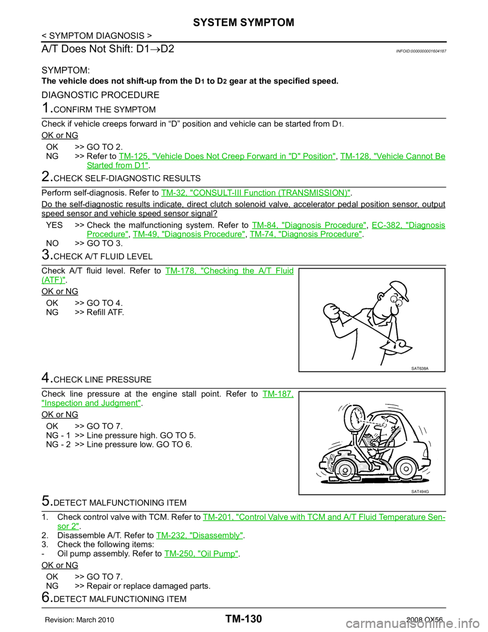
Check A/T fluid level. Refer to TM-178, "
Checking the A/T Fluid
(ATF)".
OK or NG
OK >> GO TO 4.
NG >> Refill ATF.
4.CHECK LINE PRESSURE
Check line pressure at the engine stall point. Refer to TM-187,
"Inspection and Judgment".
OK or NG
OK >> GO TO 7.
NG - 1 >> Line pressure high. GO TO 5.
NG - 2 >> Line pressure low. GO TO 6.
5.DETECT MALFUNCTIONING ITEM
1. Check control valve with TCM. Refer to TM-201, "
Control Valve with TCM and A/T Fluid Temperature Sen-
sor 2".
2. Disassemble A/T. Refer to TM-232, "
Disassembly".
3. Check the following items:
- Oil pump assembly. Refer to TM-250, "
Oil Pump".
OK or NG
OK >> GO TO 7.
NG >> Repair or replace damaged parts.
6.DETECT MALFUNCTIONING ITEM
SAT638A
SAT494G
Revision: March 2010 2008 QX56
Page 3679 of 4083
TM-132
< SYMPTOM DIAGNOSIS >
SYSTEM SYMPTOM
DIAGNOSTIC PROCEDURE
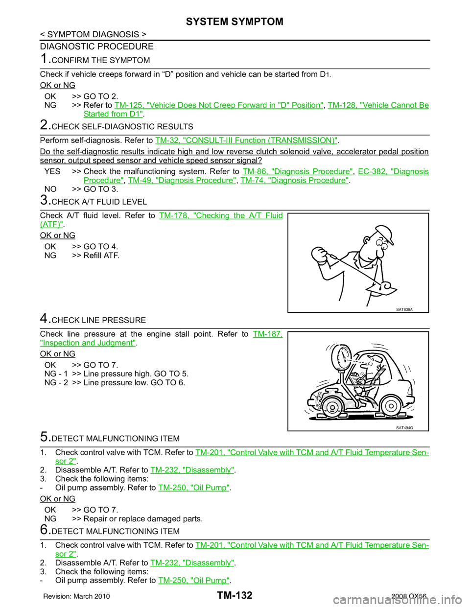
1.CONFIRM THE SYMPTOM
Check if vehicle creeps forward in “D” position and vehicle can be started from D
1.
OK or NG
OK >> GO TO 2.
NG >> Refer to TM-125, "
Vehicle Does Not Creep Forward in "D" Position", TM-128, "Vehicle Cannot Be
Started from D1".
2.CHECK SELF-DIAGNOSTIC RESULTS
Perform self-diagnosis. Refer to TM-32, "
CONSULT-III Functi on (TRANSMISSION)".
Do the self-diagnostic results indicate high and low reverse clutch solenoid valve, accelerator pedal position
sensor, output speed sensor and vehicle speed sensor signal?
YES >> Check the malfunctioning system. Refer to TM-86, "Diagnosis Procedure", EC-382, "Diagnosis
Procedure", TM-49, "Diagnosis Procedure", TM-74, "Diagnosis Procedure".
NO >> GO TO 3.
3.CHECK A/T FLUID LEVEL
Check A/T fluid level. Refer to TM-178, "
Checking the A/T Fluid
(ATF)".
OK or NG
OK >> GO TO 4.
NG >> Refill ATF.
4.CHECK LINE PRESSURE
Check line pressure at the engine stall point. Refer to TM-187,
"Inspection and Judgment".
OK or NG
OK >> GO TO 7.
NG - 1 >> Line pressure high. GO TO 5.
NG - 2 >> Line pressure low. GO TO 6.
5.DETECT MALFUNCTIONING ITEM
1. Check control valve with TCM. Refer to TM-201, "
Control Valve with TCM and A/T Fluid Temperature Sen-
sor 2".
2. Disassemble A/T. Refer to TM-232, "
Disassembly".
3. Check the following items:
- Oil pump assembly. Refer to TM-250, "
Oil Pump".
OK or NG
OK >> GO TO 7.
NG >> Repair or replace damaged parts.
6.DETECT MALFUNCTIONING ITEM
1. Check control valve with TCM. Refer to TM-201, "
Control Valve with TCM and A/T Fluid Temperature Sen-
sor 2".
2. Disassemble A/T. Refer to TM-232, "
Disassembly".
3. Check the following items:
- Oil pump assembly. Refer to TM-250, "
Oil Pump".
SAT638A
SAT494G
Revision: March 2010 2008 QX56
Page 3681 of 4083
TM-134
< SYMPTOM DIAGNOSIS >
SYSTEM SYMPTOM
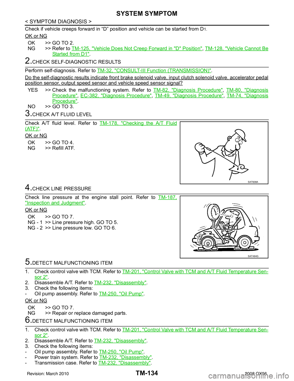
Check if vehicle creeps forward in “D” position and vehicle can be started from D1.
OK or NG
OK >> GO TO 2.
NG >> Refer to TM-125, "
Vehicle Does Not Creep Forward in "D" Position", TM-128, "Vehicle Cannot Be
Started from D1".
2.CHECK SELF-DIAGNOSTIC RESULTS
Perform self-diagnosis. Refer to TM-32, "
CONSULT-III Functi on (TRANSMISSION)".
Do the self-diagnostic results indicate front brake solenoid valve, input clutch solenoid valve, accelerator pedal
position sensor, output speed sensor and vehicle speed sensor signal?
YES >> Check the malfuncti oning system. Refer to TM-82, "Diagnosis Procedure", TM-80, "Diagnosis
Procedure", EC-382, "Diagnosis Procedure", TM-49, "Diagnosis Procedure", TM-74, "Diagnosis
Procedure".
NO >> GO TO 3.
3.CHECK A/T FLUID LEVEL
Check A/T fluid level. Refer to TM-178, "
Checking the A/T Fluid
(ATF)".
OK or NG
OK >> GO TO 4.
NG >> Refill ATF.
4.CHECK LINE PRESSURE
Check line pressure at the engine stall point. Refer to TM-187,
"Inspection and Judgment".
OK or NG
OK >> GO TO 7.
NG - 1 >> Line pressure high. GO TO 5.
NG - 2 >> Line pressure low. GO TO 6.
5.DETECT MALFUNCTIONING ITEM
1. Check control valve with TCM. Refer to TM-201, "
Control Valve with TCM and A/T Fluid Temperature Sen-
sor 2".
2. Disassemble A/T. Refer to TM-232, "
Disassembly".
3. Check the following items:
- Oil pump assembly. Refer to TM-250, "
Oil Pump".
OK or NG
OK >> GO TO 7.
NG >> Repair or replace damaged parts.
6.DETECT MALFUNCTIONING ITEM
1. Check control valve with TCM. Refer to TM-201, "
Control Valve with TCM and A/T Fluid Temperature Sen-
sor 2".
2. Disassemble A/T. Refer to TM-232, "
Disassembly".
3. Check the following items:
- Oil pump assembly. Refer to TM-250, "
Oil Pump".
- Power train system. Refer to TM-232, "
Disassembly".
- Transmission case. Refer to TM-232, "
Disassembly".
SAT638A
SAT494G
Revision: March 2010 2008 QX56
Page 3683 of 4083
TM-136
< SYMPTOM DIAGNOSIS >
SYSTEM SYMPTOM
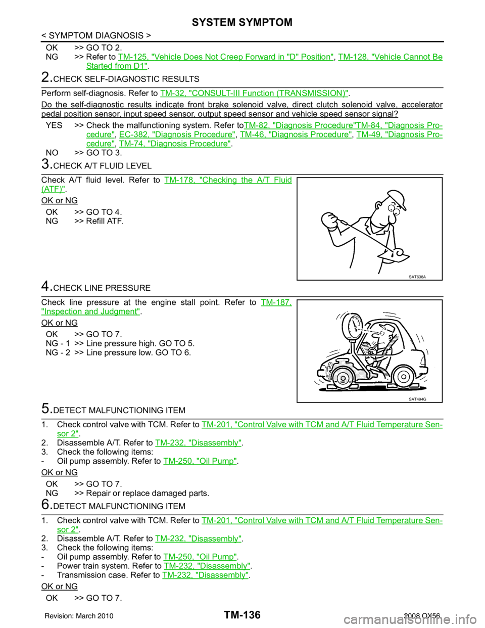
OK >> GO TO 2.
NG >> Refer to TM-125, "
Vehicle Does Not Creep Forward in "D" Position", TM-128, "Vehicle Cannot Be
Started from D1".
2.CHECK SELF-DIAGNOSTIC RESULTS
Perform self-diagnosis. Refer to TM-32, "
CONSULT-III Functi on (TRANSMISSION)".
Do the self-diagnostic results indicate front brake sol enoid valve, direct clutch solenoid valve, accelerator
pedal position sensor, input speed sensor, output speed sensor and vehicle speed sensor signal?
YES >> Check the malfunctioning system. Refer to TM-82, "Diagnosis Procedure"TM-84, "Diagnosis Pro-
cedure", EC-382, "Diagnosis Procedure", TM-46, "Diagnosis Procedure", TM-49, "Diagnosis Pro-
cedure", TM-74, "Diagnosis Procedure".
NO >> GO TO 3.
3.CHECK A/T FLUID LEVEL
Check A/T fluid level. Refer to TM-178, "
Checking the A/T Fluid
(ATF)".
OK or NG
OK >> GO TO 4.
NG >> Refill ATF.
4.CHECK LINE PRESSURE
Check line pressure at the engine stall point. Refer to TM-187,
"Inspection and Judgment".
OK or NG
OK >> GO TO 7.
NG - 1 >> Line pressure high. GO TO 5.
NG - 2 >> Line pressure low. GO TO 6.
5.DETECT MALFUNCTIONING ITEM
1. Check control valve with TCM. Refer to TM-201, "
Control Valve with TCM and A/T Fluid Temperature Sen-
sor 2".
2. Disassemble A/T. Refer to TM-232, "
Disassembly".
3. Check the following items:
- Oil pump assembly. Refer to TM-250, "
Oil Pump".
OK or NG
OK >> GO TO 7.
NG >> Repair or replace damaged parts.
6.DETECT MALFUNCTIONING ITEM
1. Check control valve with TCM. Refer to TM-201, "
Control Valve with TCM and A/T Fluid Temperature Sen-
sor 2".
2. Disassemble A/T. Refer to TM-232, "
Disassembly".
3. Check the following items:
- Oil pump assembly. Refer to TM-250, "
Oil Pump".
- Power train system. Refer to TM-232, "
Disassembly".
- Transmission case. Refer to TM-232, "
Disassembly".
OK or NG
OK >> GO TO 7.
SAT638A
SAT494G
Revision: March 2010 2008 QX56