2008 INFINITI QX56 Electrical
[x] Cancel search: ElectricalPage 3602 of 4083
P0732 2GR INCORRECT RATIOTM-55
< COMPONENT DIAGNOSIS >
CEF
G H
I
J
K L
M A
B
TM
N
O P
P0732 2GR INCORRECT RATIO
DescriptionINFOID:0000000001604055
This malfunction is detected when the A/T does not shift into 2GR position as instructed by TCM. This is not
only caused by electrical malfunction (circuits open or shorted) but also by mechanical malfunction such as
control valve sticking, improper solenoid valve operation.
On Board Diagnosis LogicINFOID:0000000001604056
• This is an OBD-II self-diagnostic item.
• Diagnostic trouble code “P0732” detected when TCM detects any inconsistency in the actual gear ratio.
Possible CauseINFOID:0000000001604057
• Harness or connectors (Solenoid circuits are open or shorted.)
• Input clutch solenoid valve
• Front brake solenoid valve
• Direct clutch solenoid valve
• High and low reverse clutch solenoid valve
• Each clutch
• Hydraulic control circuit
DTC Confirmation ProcedureINFOID:0000000001604058
CAUTION:
Always drive vehicle at a safe speed.
NOTE:
If “DTC Confirmation Procedure” has been previously performed, always turn ignition switch OFF and
wait at least 10 seconds before performing the next test.
After the repair, perform the following procedure to confirm the malfunction is eliminated.
WITH CONSULT-III
1. Start the engine and select “DATA MONITOR” mode for “TRANSMISSION” with CONSULT-III.
2. Make sure that “ATF TEMP 1” is within the following range. ATF TEMP 1: 20 °C – 140 °C
If out of range, drive vehicle to warm ATF or stop engine to cool ATF.
3. Select “2ND GR FNCTN P0732” of “DTC WORK SUPPORT” mode for “TRANSMISSION” with CON-
SULT-III.
4. Drive vehicle and maintain the following conditions.
VEHICLE SPEED: 10 km/h (6 MPH) or more
ACCELE POSI: 0.6/8 or more
ENGINE SPEED: INPUT SPEED − 50 rpm or more
INPUT SPEED: 300 rpm or more
GEAR: “2” position
MANU MODE SW: ON
5. Keep the current driving status for at least 5 consecutive seconds if CONSULT-III screen changes from “OUT OF CONDITION” to “TESTING”.
CAUTION:
If “TESTING” does not appear on CONSULT-III for a long time, select “SELF-DIAG RESULTS”. In
case a 1st trip DTC other than P0732 is shown, refer to “ TM-116, "
DTC No. Index"”.
If “COMPLETED RESULT NG” is detected, go to TM-56, "
Diagnosis Procedure".
If “STOP VEHICLE” is detec ted, go to the following step.
6. Stop vehicle.
7. Drive vehicle in “D” position allowing it to shift from 1st to 5GR and check shift timing and shift shock.
- Touch “OK” to complete the inspection when normally shifted from the 1GR to 5GR.
- Touch “NG” when an unusual shift shock, etc. occurs in spite of shifting from the 1GR to 5GR. Go to TM-
189, "Description".
-Perform TM-32, "
CONSULT-III Functi on (TRANSMISSION)" when not shifted from the 1GR to 5GR. (Nei-
ther “OK” nor “NG” are indicated.)
Revision: March 2010 2008 QX56
Page 3604 of 4083
P0733 3GR INCORRECT RATIOTM-57
< COMPONENT DIAGNOSIS >
CEF
G H
I
J
K L
M A
B
TM
N
O P
P0733 3GR INCORRECT RATIO
DescriptionINFOID:0000000001604060
This malfunction is detected when the A/T does not shift into 3GR position as instructed by TCM. This is not
only caused by electrical malfunction (circuits open or shorted) but also by mechanical malfunction such as
control valve sticking, improper solenoid valve operation.
On Board Diagnosis LogicINFOID:0000000001604061
• This is an OBD-II self-diagnostic item.
• Diagnostic trouble code “P0733” is detected when TCM detec ts any inconsistency in the actual gear ratio.
Possible CauseINFOID:0000000001604062
• Harness or connectors
(Solenoid circuits are open or shorted.)
• Input clutch solenoid valve
• Front brake solenoid valve
• Direct clutch solenoid valve
• High and low reverse clutch solenoid valve
• Each clutch
• Hydraulic control circuit
DTC Confirmation ProcedureINFOID:0000000001604063
CAUTION:
Always drive vehicle at a safe speed.
NOTE:
If “DTC Confirmation Procedure” has been previously performed, always turn ignition switch OFF and
wait at least 10 seconds before performing the next test.
After the repair, perform the following procedure to confirm the malfunction is eliminated.
WITH CONSULT-III
1. Start the engine and select “DATA MONITOR” mode for “TRANSMISSION” with CONSULT-III.
2. Make sure that “ATF TEMP 1” is within the following range. ATF TEMP 1: 20 °C – 140 °C
If out of range, drive vehicle to warm ATF or stop engine to cool ATF.
3. Select “3RD GR FNCTN P0733” of “DTC WORK SUPPORT” mode for “TRANSMISSION” with CON-
SULT-III.
4. Drive vehicle and maintain the following conditions.
VEHICLE SPEED: 10 km/h (6 MPH) or more
ACCELE POSI: 0.6/8 or more
ENGINE SPEED: INPUT SPEED − 50 rpm or more
INPUT SPEED: 300 rpm or more
GEAR: “3” position
MANU MODE SW: ON
5. Keep the current driving status for at least 5 consecutive seconds if CONSULT-III screen changes from “OUT OF CONDITION” to “TESTING”.
CAUTION:
If “TESTING” does not appear on CONSULT-III for a long time, select “SELF-DIAG RESULTS”. In
case a 1st trip DTC other than P0732 is shown, refer to “ TM-116, "
DTC No. Index"”.
If “COMPLETED RESULT NG” is detected, go to TM-58, "
Diagnosis Procedure".
If “STOP VEHICLE” is detec ted, go to the following step.
6. Stop vehicle.
7. Drive vehicle in “D” position allowing it to shift from 1GR to 5GR and check shift timing and shift shock.
- Touch “OK” to complete the inspection when normally shifted from the 1GR to 5GR.
- Touch “NG” when an unusual shift shock, etc. occurs in spite of shifting from the 1GR to 5GR. Go to TM-
189, "Description".
-Perform TM-32, "
CONSULT-III Functi on (TRANSMISSION)" when not shifted from the 1GR to 5GR. (Nei-
ther “OK” nor “NG” are indicated.)
Revision: March 2010 2008 QX56
Page 3606 of 4083
P0734 4GR INCORRECT RATIOTM-59
< COMPONENT DIAGNOSIS >
CEF
G H
I
J
K L
M A
B
TM
N
O P
P0734 4GR INCORRECT RATIO
DescriptionINFOID:0000000001604065
This malfunction is detected when the A/T does not shift into 4GR position as instructed by TCM. This is not
only caused by electrical malfunction (circuits open or shorted) but also by mechanical malfunction such as
control valve sticking, improper solenoid valve operation.
On Board Diagnosis LogicINFOID:0000000001604066
• This is an OBD-II self-diagnostic item.
• Diagnostic trouble code “P0734” is detected when TCM detec ts any inconsistency in the actual gear ratio.
Possible CauseINFOID:0000000001604067
• Harness or connectors
(Solenoid circuits are open or shorted.)
• Input clutch solenoid valve
• Front brake solenoid valve
• Direct clutch solenoid valve
• High and low reverse clutch solenoid valve
• Each clutch
• Hydraulic control circuit
DTC Confirmation ProcedureINFOID:0000000001604068
CAUTION:
Always drive vehicle at a safe speed.
NOTE:
If “DTC Confirmation Procedure” has been previously performed, always turn ignition switch OFF and
wait at least 10 seconds before performing the next test.
After the repair, perform the following procedure to confirm the malfunction is eliminated.
WITH CONSULT-III
1. Start the engine and select “DATA MONITOR” mode for “TRANSMISSION” with CONSULT-III.
2. Make sure that “ATF TEMP 1” is within the following range. ATF TEMP 1: 20 °C – 140 °C
If out of range, drive vehicle to warm ATF or stop engine to cool ATF.
3. Select “4TH GR FNCTN P0734” of “DTC WORK SUPPORT” mode for “TRANSMISSION” with CON-
SULT-III.
4. Drive vehicle and maintain the following conditions.
VEHICLE SPEED: 10 km/h (6 MPH) or more
ACCELE POSI: 0.6/8 or more
ENGINE SPEED: INPUT SPEED − 50 rpm or more
INPUT SPEED: 300 rpm or more
GEAR: “4” position
MANU MODE SW: ON
5. Keep the current driving status for at least 5 consecutive seconds if CONSULT-III screen changes from “OUT OF CONDITION” to “TESTING”.
CAUTION:
If “TESTING” does not appear on CONSULT-III for a long time, select “SELF-DIAG RESULTS”. In
case a 1st trip DTC other than P0734 is shown, refer to “ TM-116, "
DTC No. Index"”.
If “COMPLETED RESULT NG” is detected, go toTM-60, "
Diagnosis Procedure".
If “STOP VEHICLE” is detec ted, go to the following step.
6. Stop vehicle.
7. Drive vehicle in “D” position allowing it to shift from 1GR to 5GR and check shift timing and shift shock.
- Touch “OK” to complete the inspection when normally shifted from the 1GR to 5GR.
- Touch “NG” when an unusual shift shock, etc. occurs in spite of shifting from the 1GR to 5GR. Go to TM-
189, "Description".
-Perform TM-32, "
CONSULT-III Functi on (TRANSMISSION)" when not shifted from the 1GR to 5GR. (Nei-
ther “OK” nor “NG” are indicated.)
Revision: March 2010 2008 QX56
Page 3608 of 4083
P0735 5GR INCORRECT RATIOTM-61
< COMPONENT DIAGNOSIS >
CEF
G H
I
J
K L
M A
B
TM
N
O P
P0735 5GR INCORRECT RATIO
DescriptionINFOID:0000000001604070
This malfunction is detected when the A/T does not shift into 5GR position as instructed by TCM. This is not
only caused by electrical malfunction (circuits open or shorted) but also by mechanical malfunction such as
control valve sticking, improper solenoid valve operation.
On Board Diagnosis LogicINFOID:0000000001604071
• This is an OBD-II self-diagnostic item.
• Diagnostic trouble code “P0735” is detected when TCM detec ts any inconsistency in the actual gear ratio.
Possible CauseINFOID:0000000001604072
• Harness or connectors
(Solenoid circuits are open or shorted.)
• Input clutch solenoid valve
• Front brake solenoid valve
• Direct clutch solenoid valve
• High and low reverse clutch solenoid valve
• Each clutch
• Hydraulic control circuit
DTC Confirmation ProcedureINFOID:0000000001604073
CAUTION:
Always drive vehicle at a safe speed.
NOTE:
If “DTC Confirmation Procedure” has been previously performed, always turn ignition switch OFF and
wait at least 10 seconds before performing the next test.
After the repair, perform the following procedure to confirm the malfunction is eliminated.
WITH CONSULT-III
1. Start the engine and select “DATA MONITOR” mode for “TRANSMISSION” with CONSULT-III.
2. Make sure that “ATF TEMP 1” is within the following range. ATF TEMP 1: 20 °C – 140 °C
If out of range, drive vehicle to warm ATF or stop engine to cool ATF.
3. Select “5TH GR FNCTN P0735” of “DTC WORK SUPPORT” mode for “TRANSMISSION” with CON-
SULT-III.
4. Drive vehicle and maintain the following conditions.
VEHICLE SPEED: 10 km/h (6 MPH) or more
ACCELE POSI: 0.6/8 or more
ENGINE SPEED: INPUT SPEED − 50 rpm or more
INPUT SPEED: 300 rpm or more
GEAR: “5” position
MANU MODE SW: ON
5. Keep the current driving status for at least 5 consecutive seconds if CONSULT-III screen changes from “OUT OF CONDITION” to “TESTING”.
CAUTION:
If “TESTING” does not appear on CONSULT-III for a long time, select “SELF-DIAG RESULTS”. In
case a 1st trip DTC other than P0735 is shown, refer to “ TM-116, "
DTC No. Index"”.
If “COMPLETED RESULT NG” is detected, go to TM-62, "
Diagnosis Procedure".
If “STOP VEHICLE” is detec ted, go to the following step.
6. Stop vehicle.
7. Drive vehicle in “D” position allowing it to shift from 1GR to 5GR and check shift timing and shift shock.
- Touch “OK” to complete the inspection when normally shifted from the 1GR to 5GR.
- Touch “NG” when an unusual shift shock, etc. occurs in spite of shifting from the 1GR to 5GR. Go to TM-
189, "Description".
-Perform TM-32, "
CONSULT-III Functi on (TRANSMISSION)" when not shifted from the 1GR to 5GR. (Nei-
ther “OK” nor “NG” are indicated.)
Revision: March 2010 2008 QX56
Page 3612 of 4083
P0744 TORQUE CONVERTERTM-65
< COMPONENT DIAGNOSIS >
CEF
G H
I
J
K L
M A
B
TM
N
O P
P0744 TORQUE CONVERTER
DescriptionINFOID:0000000001604081
This malfunction is detected when the A/T does not lock- up.This is not only caused by electrical malfunction
(circuits open or shorted) but also by mechanical malfunc tion such as control valve sticking, improper solenoid
valve operation, etc.
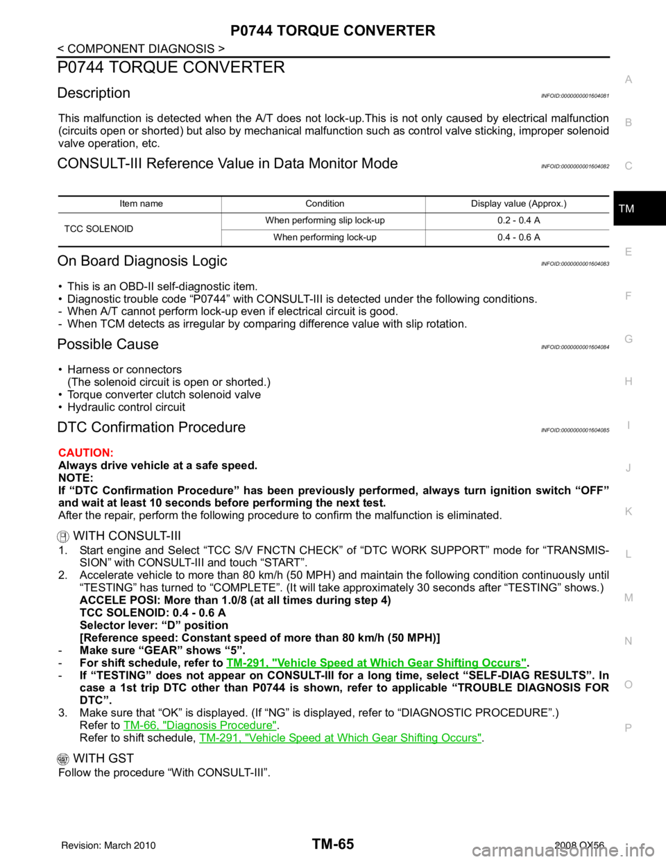
CONSULT-III Reference Val ue in Data Monitor ModeINFOID:0000000001604082
On Board Diagnosis LogicINFOID:0000000001604083
• This is an OBD-II self-diagnostic item.
• Diagnostic trouble code “P0744” with CONSULT-III is detected under the following conditions.
- When A/T cannot perform lock-up even if electrical circuit is good.
- When TCM detects as irregular by comparing difference value with slip rotation.
Possible CauseINFOID:0000000001604084
• Harness or connectors
(The solenoid circuit is open or shorted.)
• Torque converter clutch solenoid valve
• Hydraulic control circuit
DTC Confirmation ProcedureINFOID:0000000001604085
CAUTION:
Always drive vehicle at a safe speed.
NOTE:
If “DTC Confirmation Procedure” has been previously performed, always turn ignition switch “OFF”
and wait at least 10 seconds before performing the next test.
After the repair, perform the following procedure to confirm the malfunction is eliminated.
WITH CONSULT-III
1. Start engine and Select “TCC S/V FNCTN CHECK” of “DTC WORK SUPPORT” mode for “TRANSMIS- SION” with CONSULT-III and touch “START”.
2. Accelerate vehicle to more than 80 km/h (50 MPH) and maintain the following condition continuously until “TESTING” has turned to “COMPLETE”. (It will take approximately 30 seconds after “TESTING” shows.)
ACCELE POSI: More than 1.0/8 (at all times during step 4)
TCC SOLENOID: 0.4 - 0.6 A
Selector lever: “D” position
[Reference speed: Constant speed of more than 80 km/h (50 MPH)]
- Make sure “GEAR” shows “5”.
- For shift schedule, refer to TM-291, "
Vehicle Speed at Which Gear Shifting Occurs".
- If “TESTING” does not appear on CONSULT-III for a long time, select “SELF-DIAG RESULTS”. In
case a 1st trip DTC other than P0744 is shown, refer to applicable “TROUBLE DIAGNOSIS FOR
DTC”.
3. Make sure that “OK” is disp layed. (If “NG” is displayed, refer to “DIAGNOSTIC PROCEDURE”.)
Refer to TM-66, "
Diagnosis Procedure".
Refer to shift schedule, TM-291, "
Vehicle Speed at Which Gear Shifting Occurs".
WITH GST
Follow the procedure “With CONSULT-III”.
Item name Condition Display value (Approx.)
TCC SOLENOID When performing slip lock-up
0.2 - 0.4 A
When performing lock-up 0.4 - 0.6 A
Revision: March 2010 2008 QX56
Page 3637 of 4083
TM-90
< COMPONENT DIAGNOSIS >
P1774 LOW COAST BRAKE SOLENOID
P1774 LOW COAST BRAKE SOLENOID
DescriptionINFOID:0000000001604154
• Low coast brake solenoid valve is turned “ON” or “OFF” by the TCM in response to signals sent from the
transmission range switch, output speed sensor and accele rator pedal position sensor (throttle position sen-
sor). Gears will then be shifted to the optimum position.
• This is not only caused by electrical malfunction (circuits open or shorted) but also by mechanical malfunc- tion such as control valve sticking, improper solenoid valve operation.
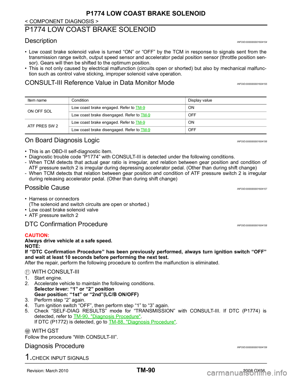
CONSULT-III Reference Value in Data Monitor ModeINFOID:0000000001604155
On Board Diagn osis LogicINFOID:0000000001604156
• This is an OBD-II self-diagnostic item.
• Diagnostic trouble code “P1774” with CONSULT-III is detected under the following conditions.
- When TCM detects that actual gear ratio is irregular, and relation between gear position and condition of
ATF pressure switch 2 is irregular during depressing accelerator pedal. (Other than during shift change)
- When TCM detects that relation between gear position and condition of ATF pressure switch 2 is irregular
during releasing accelerator pedal. (Other than during shift change)
Possible CauseINFOID:0000000001604157
• Harness or connectors
(The solenoid and switch circuits are open or shorted.)
• Low coast brake solenoid valve
• ATF pressure switch 2
DTC Confirmation ProcedureINFOID:0000000001604158
CAUTION:
Always drive vehicle at a safe speed.
NOTE:
If “DTC Confirmation Procedure” has been previously performed, always turn ignition switch “OFF”
and wait at least 10 seconds before performing the next test.
After the repair, perform the following proc edure to confirm the malfunction is eliminated.
WITH CONSULT-III
1. Start engine.
2. Accelerate vehicle to maintain the following conditions.
Selector lever: “1” or “2” position
Gear position: “1st” or “2nd”(LC/B ON/OFF)
3. Perform step “2” again.
4. Turn ignition switch “OFF”, then perform step “1” to “3” again.
5. Check “SELF-DIAG RESULTS” mode for “TRANSMISSION” with CONSULT-III. If DTC (P1774) is detected, refer to TM-90, "
Diagnosis Procedure".
If DTC (P1772) is detected, go to TM-88, "
Diagnosis Procedure".
WITH GST
Follow the procedure “With CONSULT-III”.
Diagnosis ProcedureINFOID:0000000001604159
1.CHECK INPUT SIGNALS
Item nameCondition Display value
ON OFF SOL Low coast brake engaged. Refer to
TM-9
ON
Low coast brake disengaged. Refer to TM-9
OFF
ATF PRES SW 2 Low coast brake engaged. Refer to
TM-9
ON
Low coast brake disengaged. Refer to TM-9
OFF
Revision: March 2010 2008 QX56
Page 3650 of 4083
TCM
TM-103
< ECU DIAGNOSIS >
C EF
G H
I
J
K L
M A
B
TM
N
O P
ECU DIAGNOSIS
TCM
Reference ValueINFOID:0000000001604173
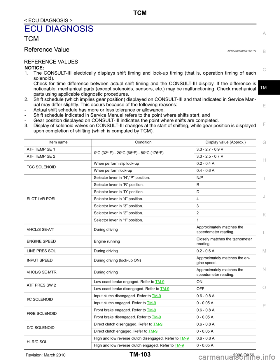
REFERENCE VALUES
NOTICE:
1. The CONSULT-III electrically displays shift timi ng and lock-up timing (that is, operation timing of each
solenoid).
Check for time difference between actual shift timi ng and the CONSULT-III display. If the difference is
noticeable, mechanical parts (except solenoids, sens ors, etc.) may be malfunctioning. Check mechanical
parts using applicable diagnostic procedures.
2. Shift schedule (which implies gear position) display ed on CONSULT-III and that indicated in Service Man-
ual may differ slightly. This occurs because of the following reasons:
- Actual shift schedule has more or less tolerance or allowance,
- Shift schedule indicated in Service Manual re fers to the point where shifts start, and
- Gear position displayed on CONSULT-III indicates the point where shifts are completed.
3. Display of solenoid valves on CONSULT-III changes at the start of shifting, while gear position is displayed upon completion of shifting (which is computed by TCM).
Item name Condition Display value (Approx.)
ATF TEMP SE 1 0°C (32 ° F) - 20 °C (68 °F) - 80 °C (176 °F) 3.3 - 2.7 - 0.9 V
ATF TEMP SE 2 3.3 - 2.5 - 0.7 V
TCC SOLENOID When perform slip lock-up
0.2 - 0.4 A
When perform lock-up 0.4 - 0.6 A
SLCT LVR POSI Selector lever in
“N”,“P” position. N/P
Selector lever in “R” position. R
Selector lever in “D” position. D
Selector lever in “4” position. 4
Selector lever in “3” position. 3
Selector lever in “2” position. 2
Selector lever in “1” position. 1
VHCL/S SE·A/T During driving Approximately matches the
speedometer reading.
ENGINE SPEED Engine running Closely matches the tachometer
reading.
LINE PRES SOL During driving 0.2 - 0.6 A
INPUT SPEED During driving (lock-up ON) Approximately matches the en-
gine speed.
VHCL/S SE·MTR During driving Approximately matches the
speedometer reading.
ATF PRES SW 2 Low coast brake engaged. Refer to
TM-9
ON
Low coast brake disengaged. Refer to TM-9
OFF
I/C SOLENOID Input clutch disengaged. Refer to
TM-9
0.6 - 0.8 A
Input clutch engaged. Refer to TM-9
0 - 0.05 A
FR/B SOLENOID Front brake engaged. Refer to
TM-9
0.6 - 0.8 A
Front brake disengaged. Refer to TM-9
0 - 0.05 A
D/C SOLENOID Direct clutch disengaged. Refer to
TM-9
0.6 - 0.8 A
Direct clutch engaged. Refer to TM-9
0 - 0.05 A
HLR/C SOL High and low reverse clutch disengaged. Refer to
TM-9
0.6 - 0.8 A
High and low reverse clutch engaged. Refer to TM-9
0 - 0.05 A
Revision: March 2010 2008 QX56
Page 3661 of 4083
TM-114
< ECU DIAGNOSIS >
TCM
Fail-Safe
INFOID:0000000001604175
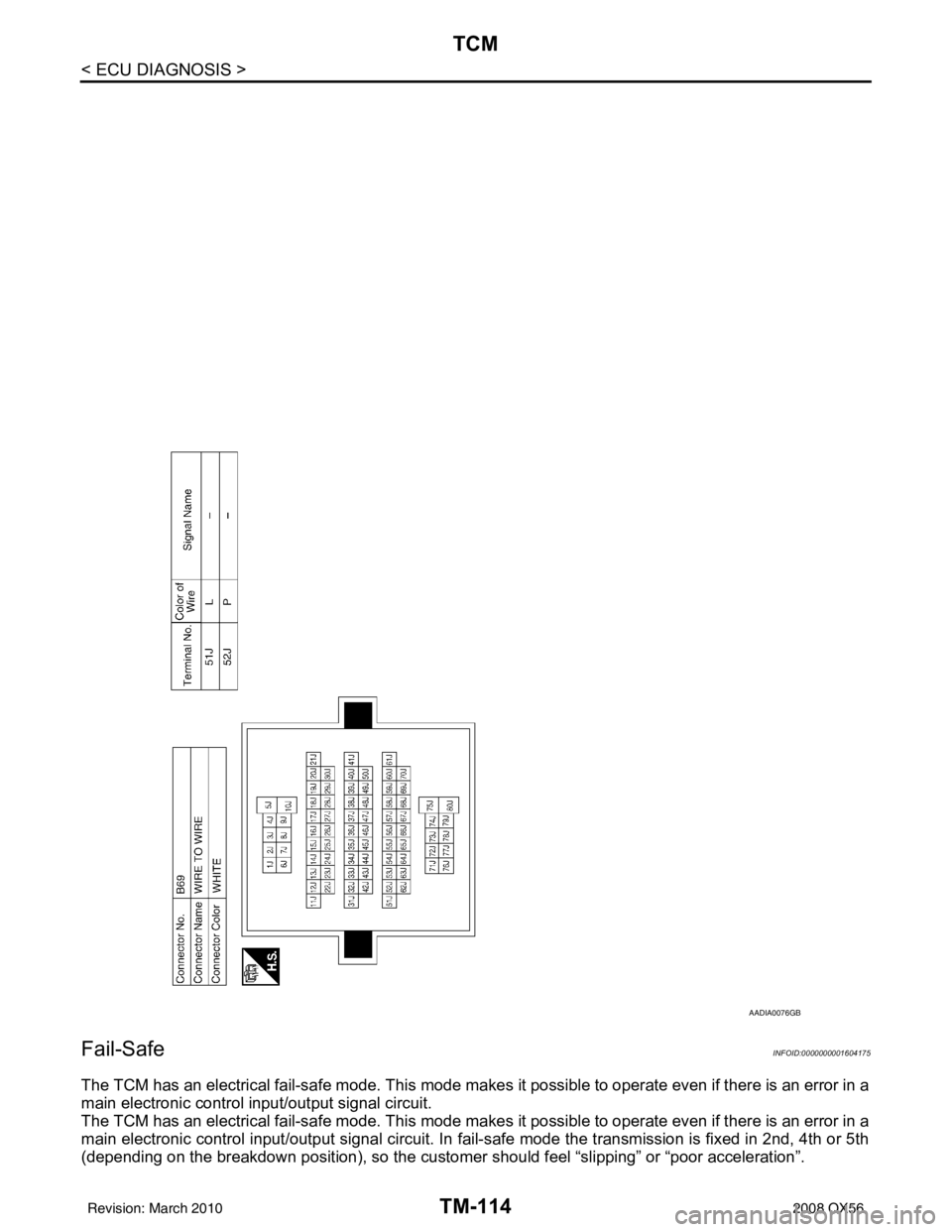
The TCM has an electrical fail-safe mode. This mode make s it possible to operate even if there is an error in a
main electronic control input/output signal circuit.
The TCM has an electrical fail-safe mode. This mode make s it possible to operate even if there is an error in a
main electronic control input/output signal circuit. In fa il-safe mode the transmission is fixed in 2nd, 4th or 5th
(depending on the breakdown position), so the customer should feel “slipping” or “poor acceleration”.
AADIA0076GB
Revision: March 2010 2008 QX56