Page 3754 of 4083
CONTROL VALVE WITH TCMTM-207
< ON-VEHICLE REPAIR >
CEF
G H
I
J
K L
M A
B
TM
N
O P
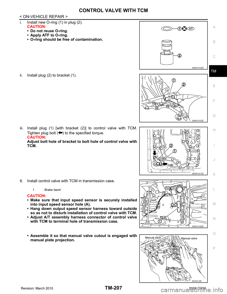
i. Install new O-ring (1) in plug (2). CAUTION:
• Do not reuse O-ring.
• Apply ATF to O-ring.
• O-ring should be free of contamination.
ii. Install plug (2) to bracket (1).
iii. Install plug (1) [with bracket (2)] to control valve with TCM. Tighten plug bolt ( ) to the specified torque.
CAUTION:
Adjust bolt hole of bracket to bolt hole of control valve with
TCM.
6. Install control valve with TCM in transmission case. CAUTION:
• Make sure that input speed sensor is securely installed
into input speed sensor hole (A).
• Hang down output speed sensor harness toward outside
so as not to disturb installati on of control valve with TCM.
• Adjust A/T assembly harness connector of control valve with TCM to terminal hole of transmission case.
• Assemble it so that manual valve cutout is engaged with
manual plate projection.
JSDIA1313ZZ
JSDIA1312ZZ
JSDIA1311ZZ
1 : Brake band
JSDIA1318ZZ
SCIA5142E
Revision: March 2010 2008 QX56
Page 3755 of 4083
TM-208
< ON-VEHICLE REPAIR >
CONTROL VALVE WITH TCM
7. Install bolts (A), (B) and (C) in control valve with TCM.
8. Tighten bolt (1A), (2B) and (3A) temporarily to prevent disloca-tion. After that tighten them in order (1 → 2 → 3).
9. Tighten control valve with TCM bolts to the specified torque.
10. After installing the A/T fluid temperature sensor 2, connect the A/T fluid temperature sensor 2 connector
as shown below.
a. Connect A/T fluid temperature sensor 2 connector (A).
b. Securely fasten terminal cord assembly and A/T fluid tempera- ture sensor 2 harness with terminal clips ( ).
11. Connect output speed sensor connector. (1)
: Front
Bolt symbol Length mm (in) Number of bolts
A 42 (1.65) 5
B 55 (2.17) 6
C 40 (1.57) 1
SCIA8074E
: Front
Bolt symbol AB C
Number of bolts 56 1
Length mm (in) 42 (1.65) 55 (2.17)40 (1.57)
Tightening torque
N·m (km-g, in-lb) 7.9 (0.81, 70)With ATF applied
7.9 (0.81, 70)
SCIA8075E
SCIA8124E
JSDIA1319ZZ
Revision: March 2010 2008 QX56
Page 3757 of 4083
TM-210
< ON-VEHICLE REPAIR >
CONTROL VALVE WITH TCM
5. Remove A/T fluid temperature sensor 2 with bracket from con-trol valve with TCM.
6. Remove bracket from A/T fluid temperature sensor 2.
Installation
CAUTION:
• If the A/T fluid temperature sensor 2 has flaws, replace it with a plug.
• After completing installa tion, check A/T fluid leakage and fluid level. Refer to TM-178, "
Checking the
A/T Fluid (ATF)".
1. Install A/T fluid temperature sensor 2 to bracket.
2. Install A/T fluid temperature sensor 2 (with bracket) in control valve with TCM. Tighten A/T fluid temperature sensor 2 bolt to
the specified torque.
CAUTION:
Adjust bolt hole of bracket to bolt hole of control valve with
TCM.
SCIA5253E
SCIA5264E
SCIA5264E
SCIA5253E
Revision: March 2010 2008 QX56
Page 3759 of 4083
TM-212
< ON-VEHICLE REPAIR >
CONTROL VALVE WITH TCM
After completing installation, check A/T fluid leakage and fluid level. Refer to TM-178, "Checking the A/
T Fluid (ATF)".
1. Install new O-ring (1) in plug (2). CAUTION:
• Do not reuse O-ring.
• Apply ATF to O-ring.
• O-ring should be free of contamination.
2. Install plug (2) to bracket (1).
3. Install plug (1) [with bracket (2)] in control valve with TCM. Tighten plug bolt ( ) to the specified torque.
CAUTION:
Adjust bolt hole of bracket to bolt hole of control valve with
TCM.
4. Install oil pan to transmission case. Refer to TM-199, "
Oil Pan".
5. Connect the negative battery terminal.
6. Refill the A/T with fluid and check the fluid level and for fluid leakage. Refer to TM-178, "
Checking the A/T
Fluid (ATF)".
JSDIA1313ZZ
JSDIA1312ZZ
JSDIA1311ZZ
Revision: March 2010 2008 QX56
Page 3762 of 4083
TRANSMISSION ASSEMBLYTM-215
< REMOVAL AND INSTALLATION >
CEF
G H
I
J
K L
M A
B
TM
N
O P
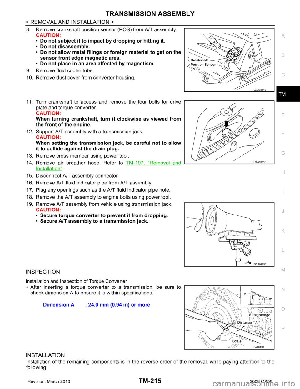
8. Remove crankshaft position sens or (POS) from A/T assembly.
CAUTION:
• Do not subject it to impact by dropping or hitting it.
• Do not disassemble.
• Do not allow metal filings or foreign material to get on the
sensor front edge magnetic area.
• Do not place in an area affected by magnetism.
9. Remove fluid cooler tube.
10. Remove dust cover from converter housing.
11. Turn crankshaft to access and remove the four bolts for drive plate and torque converter.
CAUTION:
When turning crankshaft, turn it clockwise as viewed from
the front of the engine.
12. Support A/T assembly with a transmission jack. CAUTION:
When setting the transmission jack, be careful not to allow
it to collide agai nst the drain plug.
13. Remove cross member using power tool.
14. Remove air breather hose. Refer to TM-197, "
Removal and
Installation".
15. Disconnect A/T assembly connector.
16. Remove A/T fluid indicator pipe from A/T assembly.
17. Plug any openings such as the A/T fluid indicator pipe hole.
18. Remove the A/T assembly to engine bolts using power tool.
19. Remove A/T assembly from vehicle using transmission jack. CAUTION:
• Secure torque converter to prevent it from dropping.
• Secure A/T assembly to a transmission jack.
INSPECTION
Installation and Inspection of Torque Converter
• After inserting a torque converter to a transmission, be sure to check dimension A to ensure it is within specifications.
INSTALLATION
Installation of the remaining components is in the revers e order of the removal, while paying attention to the
following:
LCIA0334E
LCIA0335E
SCIA0499E
Dimension A : 24.0 mm (0.94 in) or more
SAT017B
Revision: March 2010 2008 QX56
Page 3763 of 4083
TM-216
< REMOVAL AND INSTALLATION >
TRANSMISSION ASSEMBLY
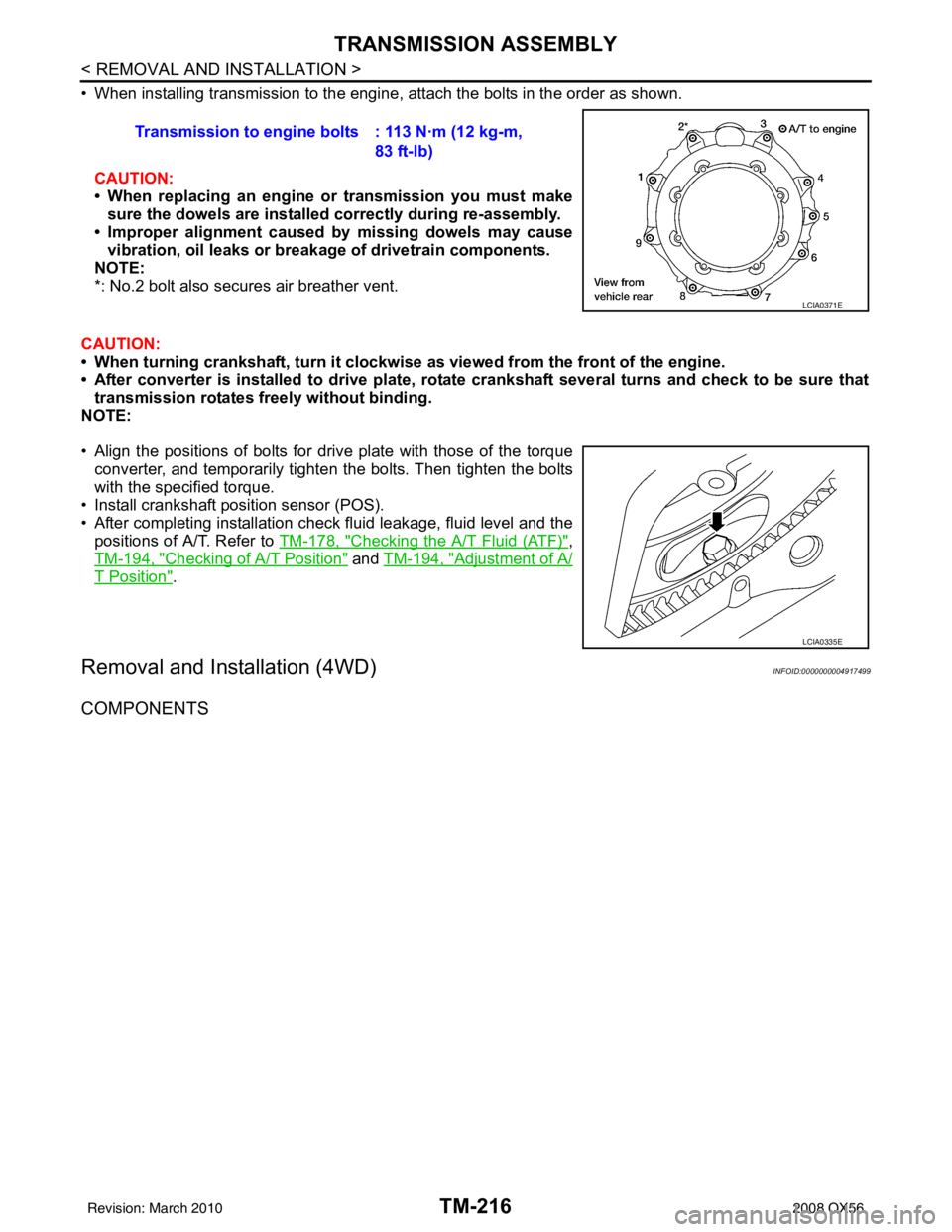
• When installing transmission to the engine, attach the bolts in the order as shown.CAUTION:
• When replacing an engine or transmission you must make
sure the dowels are installe d correctly during re-assembly.
• Improper alignment caused by missing dowels may cause
vibration, oil leaks or breakage of drivetrain components.
NOTE:
*: No.2 bolt also secures air breather vent.
CAUTION:
• When turning crankshaft, turn it clockwi se as viewed from the front of the engine.
• After converter is installed to drive plate, rota te crankshaft several turns and check to be sure that
transmission rotates fr eely without binding.
NOTE:
• Align the positions of bolts for drive plate with those of the torque converter, and temporarily tighten the bolts. Then tighten the bolts
with the specified torque.
• Install crankshaft pos ition sensor (POS).
• After completing installation check fluid leakage, fluid level and the positions of A/T. Refer to TM-178, "
Checking the A/T Fluid (ATF)",
TM-194, "
Checking of A/T Position" and TM-194, "Adjustment of A/
T Position".
Removal and Installation (4WD)INFOID:0000000004917499
COMPONENTS
Transmission to engine bolts : 113 N·m (12 kg-m,
83 ft-lb)
LCIA0371E
LCIA0335E
Revision: March 2010 2008 QX56
Page 3765 of 4083
TM-218
< REMOVAL AND INSTALLATION >
TRANSMISSION ASSEMBLY
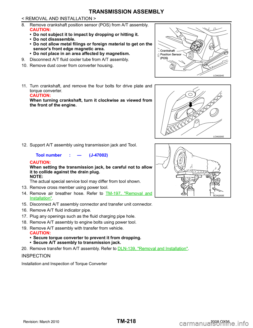
8. Remove crankshaft position sensor (POS) from A/T assembly.CAUTION:
• Do not subject it to impact by dropping or hitting it.
• Do not disassemble.
• Do not allow metal filings or fo reign material to get on the
sensor's front edge magnetic area.
• Do not place in an area affected by magnetism.
9. Disconnect A/T fluid cooler tube from A/T assembly.
10. Remove dust cover from converter housing.
11. Turn crankshaft, and remove the four bolts for drive plate and torque converter.
CAUTION:
When turning crankshaft, turn it clockwise as viewed from
the front of the engine.
12. Support A/T assembly using transmission jack and Tool. CAUTION:
When setting the transmission j ack, be careful not to allow
it to collide agai nst the drain plug.
NOTE:
The actual special service tool may differ from tool shown.
13. Remove cross member using power tool.
14. Remove air breather hose. Refer to TM-197, "
Removal and
Installation".
15. Disconnect A/T assembly connector and transfer unit connector.
16. Remove A/T fluid indicator pipe.
17. Plug any openings such as the fluid charging pipe hole.
18. Remove A/T assembly to engine bolts using power tool.
19. Remove A/T assembly with transfer from vehicle. CAUTION:
• Secure torque converter to prevent it from dropping.
• Secure A/T assembly to transmission jack.
20. Remove transfer from A/T assembly. Refer to DLN-139, "
Removal and Installation".
INSPECTION
Installation and Inspection of Torque Converter
LCIA0334E
LCIA0335E
Tool number : — (J-47002)
SCIA2203E
Revision: March 2010 2008 QX56
Page 3766 of 4083
TRANSMISSION ASSEMBLYTM-219
< REMOVAL AND INSTALLATION >
CEF
G H
I
J
K L
M A
B
TM
N
O P
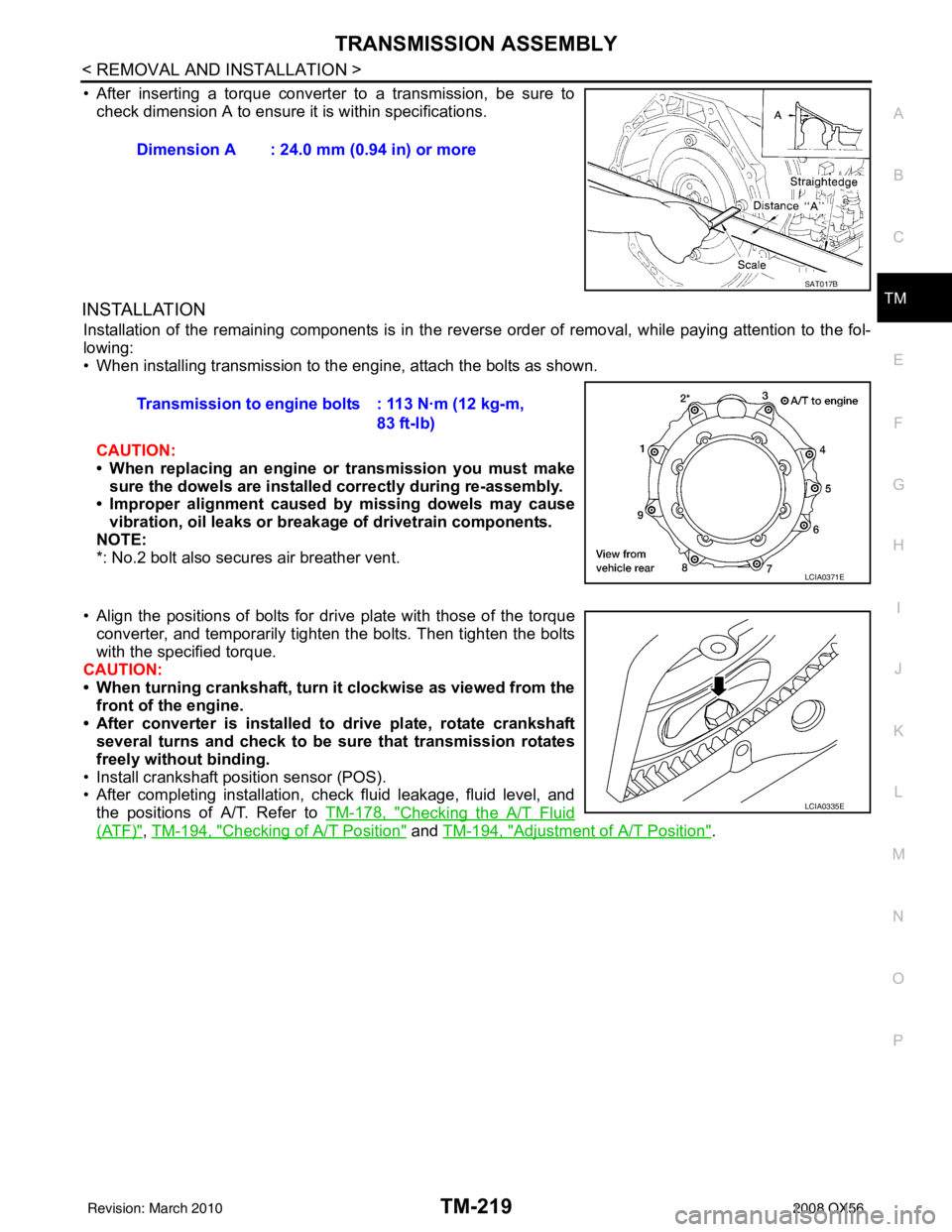
• After inserting a torque converter to a transmission, be sure to check dimension A to ensure it is within specifications.
INSTALLATION
Installation of the remaining components is in the revers e order of removal, while paying attention to the fol-
lowing:
• When installing transmission to the engine, attach the bolts as shown.
CAUTION:
• When replacing an engine or transmission you must make sure the dowels are installed correctly during re-assembly.
• Improper alignment caused by missing dowels may cause
vibration, oil leaks or breakage of drivetrain components.
NOTE:
*: No.2 bolt also secures air breather vent.
• Align the positions of bolts for dr ive plate with those of the torque
converter, and temporarily tighten the bolts. Then tighten the bolts
with the specified torque.
CAUTION:
• When turning crankshaft, turn it clockwise as viewed from the
front of the engine.
• After converter is installed to drive plate, rotate crankshaft several turns and check to be sure that transmission rotates
freely without binding.
• Install crankshaft position sensor (POS).
• After completing installation, check fluid leakage, fluid level, and the positions of A/T. Refer to TM-178, "
Checking the A/T Fluid
(ATF)", TM-194, "Checking of A/T Position" and TM-194, "Adjustment of A/T Position".
Dimension A : 24.0 mm (0.94 in) or more
SAT017B
Transmission to engine bolts : 113 N·m (12 kg-m,
83 ft-lb)
LCIA0371E
LCIA0335E
Revision: March 2010 2008 QX56