2008 INFINITI QX56 stop start
[x] Cancel search: stop startPage 3739 of 4083
TM-192
< ON-VEHICLE MAINTENANCE >
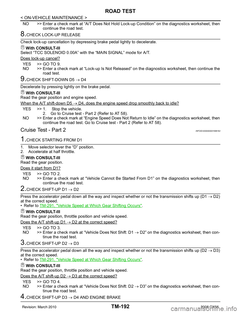
ROAD TEST
NO >> Enter a check mark at “A/T Does Not Hold Lock-up Condition” on the diagnostics worksheet, thencontinue the road test.
8.CHECK LOCK-UP RELEASE
Check lock-up cancellation by depressing brake pedal lightly to decelerate. With CONSULT-III
Select “TCC SOLENOID 0.00A” with the “MAIN SIGNAL” mode for A/T.
Does lock-up cancel?
YES >> GO TO 9.
NO >> Enter a check mark at “Lock-up Is Not Released” on the diagnostics worksheet, then continue the road test.
9.CHECK SHIFT-DOWN D5 → D4
Decelerate by pressing lightly on the brake pedal. With CONSULT-III
Read the gear position and engine speed.
When the A/T shift-down D5
→ D4, does the engine speed drop smoothly back to idle?
YES >> 1. Stop the vehicle. 2. Go to Cruise test - Part 2 (Refer to AT 58).
NO >> Enter a check mark at “Engine Speed Does Not Return to Idle” on the diagnostics worksheet, then continue the road test. Go to Cruise test - Part 2 (Refer to AT 58).
Cruise Test - Part 2INFOID:0000000001696162
1.CHECK STARTING FROM D1
1. Move selector lever the “D” position.
2. Accelerate at half throttle. With CONSULT-III
Read the gear position.
Does it start from D1?
YES >> GO TO 2.
NO >> Enter a check mark at “Vehicle Cannot Be Started From D1” on the diagnostics worksheet, then continue the road test.
2.CHECK SHIFT-UP D1 → D2
Press the accelerator pedal down all the way and ins pect whether or not the transmission shifts up (D1 → D2)
at the correct speed.
• Refer to TM-291, "
Vehicle Speed at Which Gear Shifting Occurs".
With CONSULT-III
Read the gear position, throttle position and vehicle speed.
Does the A/T shift-up D1
→ D2 at the correct speed?
YES >> GO TO 3.
NO >> Enter a check mark at “Vehicle Does Not Shift: D1 → D2” on the diagnostics worksheet, then con-
tinue the road test.
3.CHECK SHIFT-UP D2 → D3
Press the accelerator pedal down all the way and ins pect whether or not the transmission shifts up (D2 → D3)
at the correct speed.
• Refer to TM-291, "
Vehicle Speed at Which Gear Shifting Occurs".
With CONSULT-III
Read the gear position, throttle position and vehicle speed.
Does the A/T shift-up D2
→ D3 at the correct speed?
YES >> GO TO 4.
NO >> Enter a check mark at “Vehicle Does Not Shift: D2 → D3” on the diagnostics worksheet, then con-
tinue the road test.
4.CHECK SHIFT-UP D3 → D4 AND ENGINE BRAKE
Revision: March 2010 2008 QX56
Page 3741 of 4083
TM-194
< ON-VEHICLE MAINTENANCE >
A/T POSITION
A/T POSITION
Checking of A/T PositionINFOID:0000000004917429
With the shift selector in the “P” position, turn the ignition switch to the ON position with the engine OFF.
Confirm that the following conditions apply.
• The shift selector can be shifted from the “P ” position only when the brake pedal is depressed.
• The shift selector stops at each position with the feel of engagement when it is moved through all the posi-
tions.
• There is no excessive effort, sticking, noise or rattle.
• The actual position of the shift selector matches the position shown by the shift position indicator and the A/
T body.
• The back-up lamps illuminate only when the shift selector is placed in the “R” position.
• The back-up lamps do not illuminate when the shift selector is pushed against the “R” position when in the
“P” or “N” position.
• The engine can only be started with the shift selector in the “P” and “N” positions.
• The A/T is locked completely when in the “P” position.
Adjustment of A/T PositionINFOID:0000000004917428
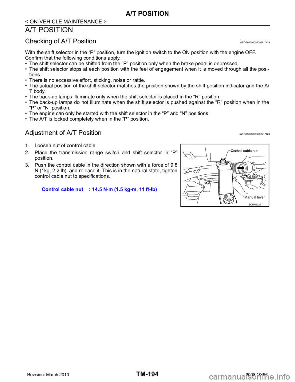
1. Loosen nut of control cable.
2. Place the transmission range switch and shift selector in “P”
position.
3. Push the control cable in the di rection shown with a force of 9.8
N (1kg, 2.2 lb), and release it. This is in the natural state, tighten
control cable nut to specifications.
Control cable nut : 14.5 N·m (1.5 kg-m, 11 ft-lb)
SCIA6532E
Revision: March 2010 2008 QX56
Page 3743 of 4083
TM-196
< ON-VEHICLE REPAIR >
SHIFT CONTROL SYSTEM
Checking of A/T Position
INFOID:0000000004917432
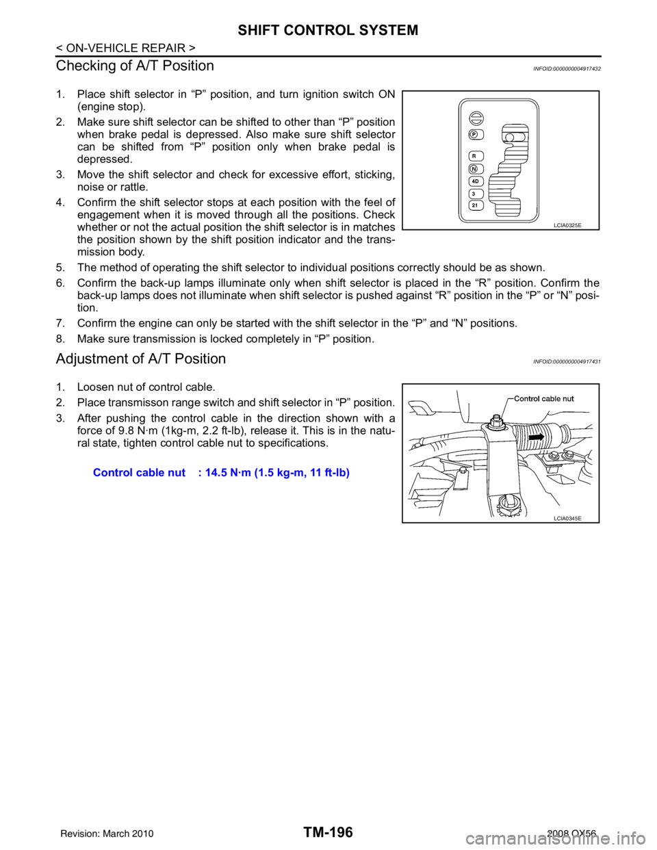
1. Place shift selector in “P” position, and turn ignition switch ON (engine stop).
2. Make sure shift selector can be shifted to other than “P” position when brake pedal is depressed. Also make sure shift selector
can be shifted from “P” position only when brake pedal is
depressed.
3. Move the shift selector and check for excessive effort, sticking, noise or rattle.
4. Confirm the shift selector stop s at each position with the feel of
engagement when it is moved through all the positions. Check
whether or not the actual position the shift selector is in matches
the position shown by the shift position indicator and the trans-
mission body.
5. The method of operating the shift selector to individual positions correctly should be as shown.
6. Confirm the back-up lamps illuminate only when shift sele ctor is placed in the “R” position. Confirm the
back-up lamps does not illuminate when shift selector is pushed against “R” position in the “P” or “N” posi-
tion.
7. Confirm the engine can only be started with the shift selector in the “P” and “N” positions.
8. Make sure transmission is locked completely in “P” position.
Adjustment of A/T PositionINFOID:0000000004917431
1. Loosen nut of control cable.
2. Place transmisson range switch and shift selector in “P” position.
3. After pushing the control cable in the direction shown with a force of 9.8 N·m (1kg-m, 2.2 ft-lb), release it. This is in the natu-
ral state, tighten control cable nut to specifications.
LCIA0325E
Control cable nut : 14.5 N·m (1.5 kg-m, 11 ft-lb)
LCIA0345E
Revision: March 2010 2008 QX56
Page 3906 of 4083
WCS
COMBINATION METERWCS-29
< ECU DIAGNOSIS >
C
DE
F
G H
I
J
K L
M B A
O P
ECU DIAGNOSIS
COMBINATION METER
Reference ValueINFOID:0000000004871168
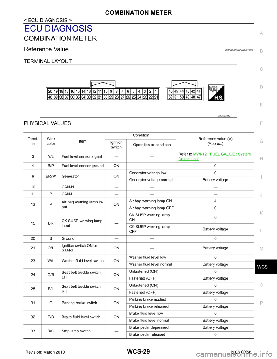
TERMINAL LAYOUT
PHYSICAL VALUES
WKIA5724E
Te r m i - nal Wire
color Item Condition
Reference value (V)
(Approx.)
Ignition
switch Operation or condition
3 Y/L Fuel level sensor signal — —Refer to
MWI-12, "
FUEL GAUGE : System
Description".
4 B/P Fuel level sensor ground ON —0
6 BR/W Generator ONGenerator voltage low
0
Generator voltage normal Battery voltage
10 L CAN-H —— —
11 P C A N - L —— —
13 P Air bag warning lamp in-
put ONAir bag warning lamp ON
4
Air bag warning lamp OFF 0
15 BR CK SUSP warning lamp
input —CK SUSP warning lamp
ON
0
CK SUSP warning lamp
OFF Battery voltage
20 B Ground —— 0
21 O/L Ignition switch ON or
START ON
— Battery voltage
23 W/L Washer fluid level switch ON Washer fluid level low
0
Washer fluid level normal Battery voltage
24 O/B Seat belt buckle switch
LH ONUnfastened (ON)
0
Fastened (OFF) Battery voltage
25 P/L Seat belt buckle switch
RH ONUnfastened (ON)
0
Fastened (OFF) Battery voltage
31 G Parking brake switch ON Parking brake applied
0
Parking brake released Battery voltage
32 P/B Brake fluid level switch ON Brake fluid level low
0
Brake fluid level normal Battery voltage
33 R/G Stop lamp switch —Brake pedal depressed
Battery voltage
Brake pedal released 0
Revision: March 2010 2008 QX56
Page 4005 of 4083
WW-8
< FUNCTION DIAGNOSIS >
REAR WIPER AND WASHER SYSTEM
REAR WIPER AND WASHER SYSTEM
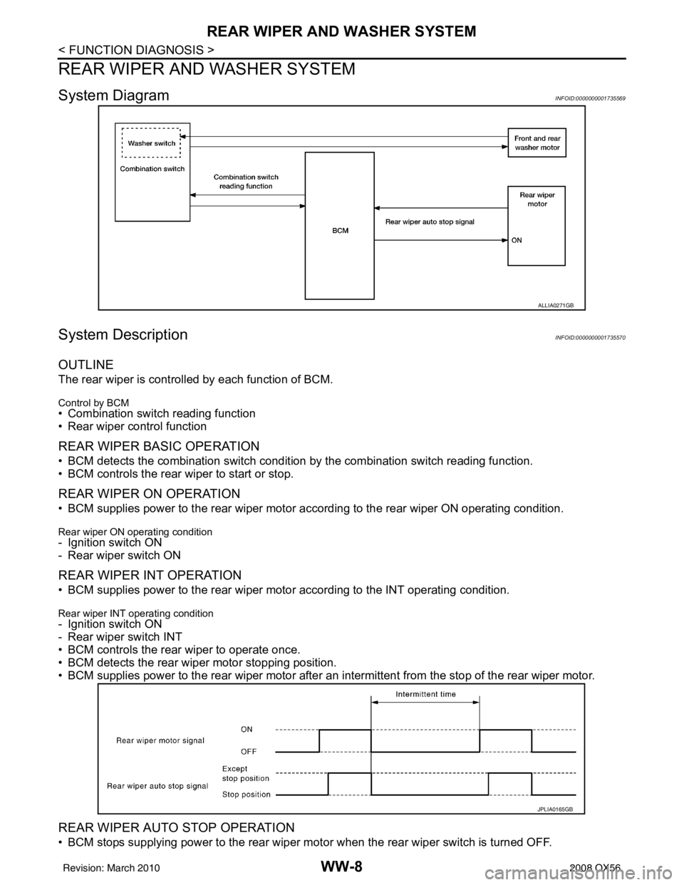
System DiagramINFOID:0000000001735569
System DescriptionINFOID:0000000001735570
OUTLINE
The rear wiper is controlled by each function of BCM.
Control by BCM• Combination switch reading function
• Rear wiper control function
REAR WIPER BASIC OPERATION
• BCM detects the combination switch condition by the combination switch reading function.
• BCM controls the rear wiper to start or stop.
REAR WIPER ON OPERATION
• BCM supplies power to the rear wiper motor ac cording to the rear wiper ON operating condition.
Rear wiper ON operating condition
- Ignition switch ON
- Rear wiper switch ON
REAR WIPER INT OPERATION
• BCM supplies power to the rear wiper motor according to the INT operating condition.
Rear wiper INT operating condition- Ignition switch ON
- Rear wiper switch INT
• BCM controls the rear wiper to operate once.
• BCM detects the rear wiper motor stopping position.
• BCM supplies power to the rear wiper motor after an intermittent from the stop of the rear wiper motor.
REAR WIPER AUTO STOP OPERATION
• BCM stops supplying power to the rear wiper motor when the rear wiper switch is turned OFF.
ALLIA0271GB
JPLIA0165GB
Revision: March 2010 2008 QX56
Page 4013 of 4083
![INFINITI QX56 2008 Factory Service Manual WW-16
< FUNCTION DIAGNOSIS >
DIAGNOSIS SYSTEM (IPDM E/R)
ACTIVE TEST
Te s t i t e m
Monitor Item[Unit] MAIN SIG-
NALS Description
MOTOR FAN REQ
[1/2/3/4] ×Displays the status of the cooling fan spee INFINITI QX56 2008 Factory Service Manual WW-16
< FUNCTION DIAGNOSIS >
DIAGNOSIS SYSTEM (IPDM E/R)
ACTIVE TEST
Te s t i t e m
Monitor Item[Unit] MAIN SIG-
NALS Description
MOTOR FAN REQ
[1/2/3/4] ×Displays the status of the cooling fan spee](/manual-img/42/57030/w960_57030-4012.png)
WW-16
< FUNCTION DIAGNOSIS >
DIAGNOSIS SYSTEM (IPDM E/R)
ACTIVE TEST
Te s t i t e m
Monitor Item[Unit] MAIN SIG-
NALS Description
MOTOR FAN REQ
[1/2/3/4] ×Displays the status of the cooling fan speed request signal received from ECM via
CAN communication.
A/C COMP REQ
[OFF/ON] ×Displays the status of the A/C request signal received from AV control unit via
CAN communication.
TA I L & C L R R E Q
[OFF/ON] ×
Displays the status of the position light request signal received from BCM via CAN
communication.
HL LO REQ
[OFF/ON] ×Displays the status of the low beam request signal received from BCM via CAN
communication.
HL HI REQ
[OFF/ON] ×Displays the status of the high beam request signal received from BCM via CAN
communication.
FR FOG REQ
[OFF/ON] ×
Displays the status of the front fog lamp request signal received from BCM via
CAN communication.
HL WASHER REQ
[OFF/ON] NOTE:
This item is displayed, but cannot be monitored.
FR WIP REQ
[STOP/1LOW/LOW/HI] ×Displays the status of the front wiper request signal received from BCM via CAN
communication.
WIP AUTO STOP
[STOP P/ACT P] ×
Displays the status of the front wiper auto stop signal judged by IPDM E/R.
WIP PROT
[OFF/Block] ×
Displays the status of the front wiper fail-safe operation judged by IPDM E/R.
ST RLY REQ
[OFF/ON] Displays the status of the starter request signal received from ECM via CAN com-
munication.
IGN RLY
[OFF/ON] ×
Displays the status of the ignition relay judged by IPDM E/R.
RR DEF REQ
[OFF/ON] ×Displays the status of the rear defogger request signal received from AV control
unit via CAN communication.
OIL P SW
[OPEN/CLOSE] Displays the status of the oil pressure switch judged by IPDM E/R.
DTRL REQ
[OFF] Displays the status of the daytime light request signal received from BCM via CAN
communication.
HOOD SW
[OPEN/CLOSE] Displays the status of the hood switch judged by IPDM E/R.
THFT HRN REQ
[OFF/ON] Displays the status of the theft warning horn request signal received from BCM
via CAN communication.
HORN CHIRP
[OFF/ON] Displays the status of the horn reminder signal received from BCM via CAN com-
munication.
Test item
Operation Description
REAR DEFOGGER OFF
OFF
ON Operates rear window defogger relay.
FRONT WIPER OFF
OFF
LO Operates the front wiper relay.
HI Operates the front wiper relay and front wiper high relay.
MOTOR FAN 1O
FF
2O FF
3 Operates the cooling fan relay.
4 Operates the cooling fan relay.
Revision: March 2010 2008 QX56
Page 4016 of 4083
FRONT WIPER MOTOR LO CIRCUITWW-19
< COMPONENT DIAGNOSIS >
C
DE
F
G H
I
J
K
M A
B
WW
N
O P
FRONT WIPER MOTOR LO CIRCUIT
Component Function CheckINFOID:0000000001735579
1. CHECK FRONT WIPER LO OPERATION
IPDM E/R AUTO ACTIVE TEST
1. Start IPDM E/R auto active test. Refer to PCS-12, "
Diagnosis Description".
2. Check that the front wiper operates at the LO operation.
CONSULT-III ACTIVE TEST
1. Select "FRONT WIPER" of IPDM E/R active test item.
2. While operating the test item, check front wiper operation.
Is front wiper (LO) operation normal?
YES >> Front wiper motor LO circuit is normal.
NO >> Refer to WW-19, "
Diagnosis Procedure".
Diagnosis ProcedureINFOID:0000000001735580
1. CHECK FRONT WIPER MOTOR FUSE
1. Turn the ignition switch OFF.
2. Check that the following fuse is not blown.
Is the fuse blown?
YES >> GO TO 2
NO >> GO TO 3
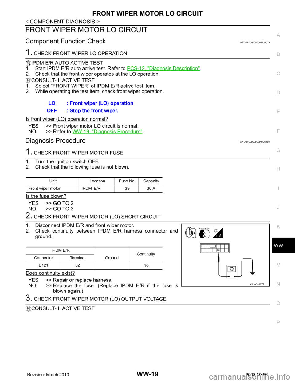
2. CHECK FRONT WIPER MOTOR (LO) SHORT CIRCUIT
1. Disconnect IPDM E/R and front wiper motor.
2. Check continuity between IPDM E/R harness connector and ground.
Does continuity exist?
YES >> Repair or replace harness.
NO >> Replace the fuse. (Replace IPDM E/R if the fuse is blown again.)
3. CHECK FRONT WIPER MOTOR (LO) OUTPUT VOLTAGE
CONSULT-III ACTIVE TEST LO : Front wiper (LO) operation
OFF : Stop the front wiper.
Unit Location Fuse No. Capacity
Front wiper motor IPDM E/R39 30 A
IPDM E/R
GroundContinuity
Connector Terminal
E121 32 No
ALLIA0447ZZ
Revision: March 2010 2008 QX56
Page 4018 of 4083
FRONT WIPER MOTOR HI CIRCUITWW-21
< COMPONENT DIAGNOSIS >
C
DE
F
G H
I
J
K
M A
B
WW
N
O P
FRONT WIPER MOTOR HI CIRCUIT
Component Function CheckINFOID:0000000001735581
1. CHECK FRONT WIPER HI OPERATION
IPDM E/R AUTO ACTIVE TEST
1. Start IPDM E/R auto active test. Refer to PCS-12, "
Diagnosis Description".
2. Check that the front wiper operates at the HI operation.
CONSULT-III ACTIVE TEST
1. Select "FRONT WIPER" of IPDM E/R active test item.
2. While operating the test item, check front wiper operation.
Is front wiper (HI) operation normal?
YES >> Front wiper motor HI circuit is normal.
NO >> Refer to WW-21, "
Diagnosis Procedure".
Diagnosis ProcedureINFOID:0000000001735582
1. CHECK FRONT WIPER MOTOR FUSE
1. Turn the ignition switch OFF.
2. Check that the following fuse is not blown.
Is the fuse blown?
YES >> GO TO 2
NO >> GO TO 3
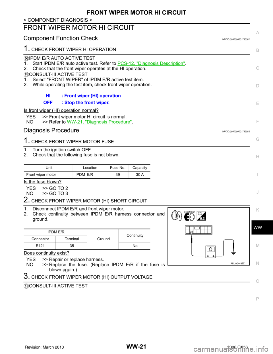
2. CHECK FRONT WIPER MOTOR (HI) SHORT CIRCUIT
1. Disconnect IPDM E/R and front wiper motor.
2. Check continuity between IPDM E/R harness connector and ground.
Does continuity exist?
YES >> Repair or replace harness.
NO >> Replace the fuse. (Replace IPDM E/R if the fuse is blown again.)
3. CHECK FRONT WIPER MOTOR (HI) OUTPUT VOLTAGE
CONSULT-III ACTIVE TEST HI : Front wiper (HI) operation
OFF : Stop the front wiper.
Unit Location Fuse No. Capacity
Front wiper motor IPDM E/R39 30 A
IPDM E/R
GroundContinuity
Connector Terminal
E121 35 No
ALLIA0448ZZ
Revision: March 2010 2008 QX56