2008 INFINITI QX56 stop start
[x] Cancel search: stop startPage 2594 of 4083

OIL COOLERLU-13
< ON-VEHICLE REPAIR >
C
DE
F
G H
I
J
K L
M A
LU
NP
O
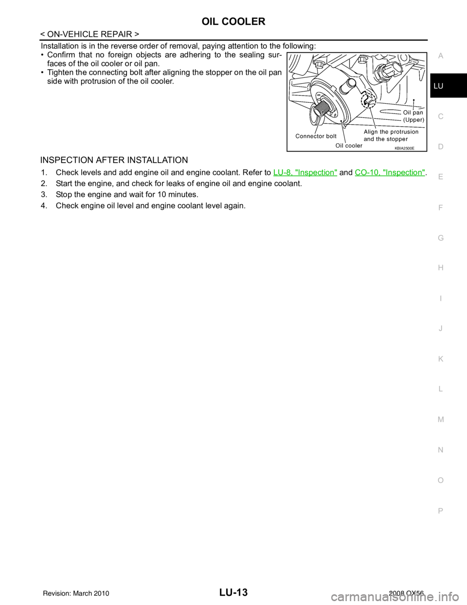
Installation is in the reverse order of removal, paying attention to the following:
• Confirm that no foreign objects are adhering to the sealing sur-
faces of the oil cooler or oil pan.
• Tighten the connecting bolt after aligning the stopper on the oil pan side with protrusion of the oil cooler.
INSPECTION AFTER INSTALLATION
1. Check levels and add engine oil and engine coolant. Refer to LU-8, "Inspection" and CO-10, "Inspection".
2. Start the engine, and check for leaks of engine oil and engine coolant.
3. Stop the engine and wait for 10 minutes.
4. Check engine oil level and engine coolant level again.
KBIA2500E
Revision: March 2010 2008 QX56
Page 2595 of 4083

LU-14
< ON-VEHICLE REPAIR >
OIL PUMP
OIL PUMP
Removal and InstallationINFOID:0000000001538848
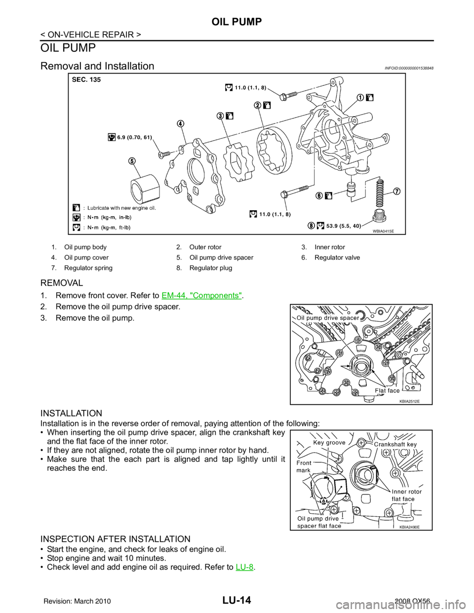
REMOVAL
1. Remove front cover. Refer to EM-44, "Components".
2. Remove the oil pump drive spacer.
3. Remove the oil pump.
INSTALLATION
Installation is in the reverse order of removal, paying attention of the following:
• When inserting the oil pump drive spacer, align the crankshaft key and the flat face of the inner rotor.
• If they are not aligned, rotate the oil pump inner rotor by hand.
• Make sure that the each part is aligned and tap lightly until it
reaches the end.
INSPECTION AFTER INSTALLATION
• Start the engine, and check for leaks of engine oil.
• Stop engine and wait 10 minutes.
• Check level and add engine oil as required. Refer to LU-8
.
WBIA0415E
1. Oil pump body2. Outer rotor 3. Inner rotor
4. Oil pump cover 5. Oil pump drive spacer 6. Regulator valve
7. Regulator spring 8. Regulator plug
KBIA2512E
KBIA2490E
Revision: March 2010 2008 QX56
Page 2617 of 4083

ENGINE MAINTENANCEMA-19
< ON-VEHICLE MAINTENANCE >
C
DE
F
G H
I
J
K L
M B
MA
N
O A
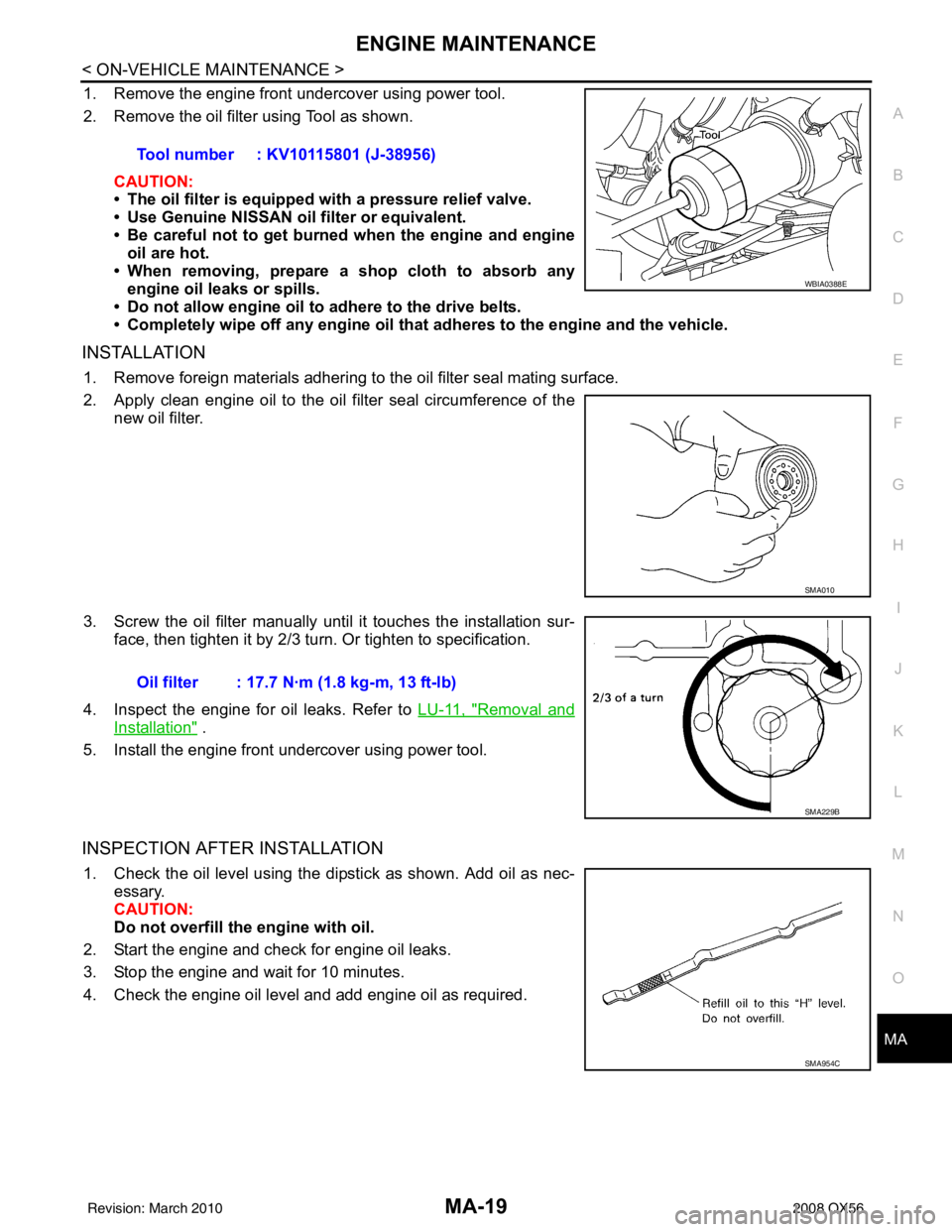
1. Remove the engine front undercover using power tool.
2. Remove the oil filter using Tool as shown.
CAUTION:
• The oil filter is equipped with a pressure relief valve.
• Use Genuine NISSAN oil filter or equivalent.
• Be careful not to get burned when the engine and engine
oil are hot.
• When removing, prepare a s hop cloth to absorb any
engine oil leaks or spills.
• Do not allow engine oil to adhere to the drive belts.
• Completely wipe off any engine oil that adheres to the engine and the vehicle.
INSTALLATION
1. Remove foreign materials adhering to the oil filter seal mating surface.
2. Apply clean engine oil to the oil filter seal circumference of the
new oil filter.
3. Screw the oil filter manually unt il it touches the installation sur-
face, then tighten it by 2/3 turn. Or tighten to specification.
4. Inspect the engine for oil leaks. Refer to LU-11, "
Removal and
Installation" .
5. Install the engine front undercover using power tool.
INSPECTION AFTER INSTALLATION
1. Check the oil level using the dipstick as shown. Add oil as nec- essary.
CAUTION:
Do not overfill th e engine with oil.
2. Start the engine and check for engine oil leaks.
3. Stop the engine and wait for 10 minutes.
4. Check the engine oil level and add engine oil as required. Tool number : KV10115801 (J-38956)
WBIA0388E
SMA010
Oil filter : 17.7 N·m (1.8 kg-m, 13 ft-lb)
SMA229B
SMA954C
Revision: March 2010
2008 QX56
Page 2687 of 4083

MWI-42
< ECU DIAGNOSIS >
COMBINATION METER
ECU DIAGNOSIS
COMBINATION METER
Reference ValueINFOID:0000000001691309
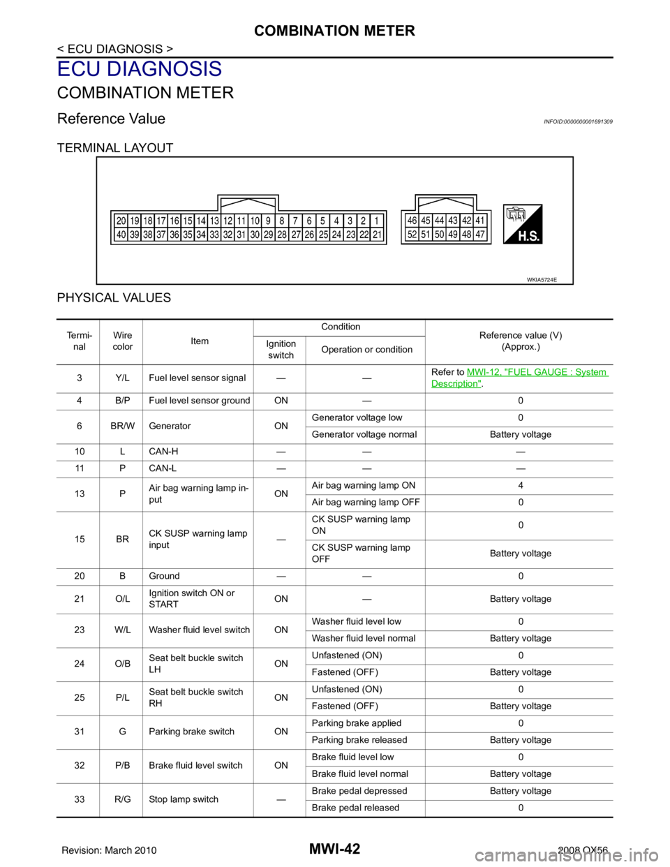
TERMINAL LAYOUT
PHYSICAL VALUES
WKIA5724E
Te r m i -nal Wire
color Item Condition
Reference value (V)
(Approx.)
Ignition
switch Operation or condition
3 Y/L Fuel level sensor signal — —Refer to MWI-12, "
FUEL GAUGE : System
Description".
4 B/P Fuel level sensor ground ON —0
6 BR/W Generator ONGenerator voltage low
0
Generator voltage normal Battery voltage
10 L CAN-H —— —
11 P C A N - L —— —
13 P Air bag warning lamp in-
put ONAir bag warning lamp ON
4
Air bag warning lamp OFF 0
15 BR CK SUSP warning lamp
input —CK SUSP warning lamp
ON
0
CK SUSP warning lamp
OFF Battery voltage
20 B Ground —— 0
21 O/L Ignition switch ON or
START ON
— Battery voltage
23 W/L Washer fluid level switch ON Washer fluid level low
0
Washer fluid level normal Battery voltage
24 O/B Seat belt buckle switch
LH ONUnfastened (ON)
0
Fastened (OFF) Battery voltage
25 P/L Seat belt buckle switch
RH ONUnfastened (ON)
0
Fastened (OFF) Battery voltage
31 G Parking brake switch ON Parking brake applied
0
Parking brake released Battery voltage
32 P/B Brake fluid level switch ON Brake fluid level low
0
Brake fluid level normal Battery voltage
33 R/G Stop lamp switch —Brake pedal depressed
Battery voltage
Brake pedal released 0
Revision: March 2010 2008 QX56
Page 2743 of 4083
![INFINITI QX56 2008 Factory Service Manual PCS-10
< FUNCTION DIAGNOSIS >[IPDM E/R]
POWER CONSUMPTION CONTROL SYSTEM
POWER CONSUMPTIO
N CONTROL SYSTEM
System DiagramINFOID:0000000001696487
System DescriptionINFOID:0000000001696488
OUTLINE
• I INFINITI QX56 2008 Factory Service Manual PCS-10
< FUNCTION DIAGNOSIS >[IPDM E/R]
POWER CONSUMPTION CONTROL SYSTEM
POWER CONSUMPTIO
N CONTROL SYSTEM
System DiagramINFOID:0000000001696487
System DescriptionINFOID:0000000001696488
OUTLINE
• I](/manual-img/42/57030/w960_57030-2742.png)
PCS-10
< FUNCTION DIAGNOSIS >[IPDM E/R]
POWER CONSUMPTION CONTROL SYSTEM
POWER CONSUMPTIO
N CONTROL SYSTEM
System DiagramINFOID:0000000001696487
System DescriptionINFOID:0000000001696488
OUTLINE
• IPDM E/R incorporates a power consumption control function that reduces the power consumption accord-
ing to the vehicle status.
• IPDM E/R changes its status (control mode) with the sleep wake up signal received from BCM via CAN com-
munication.
Normal mode (wake-up)- CAN communication is normally performed with other control units.
- Individual unit control by IPDM E/R is normally performed.
Low power consumption mode (sleep)- Low power consumption control is active.
- CAN transmission is stopped.
SLEEP MODE ACTIVATION
• IPDM E/R judges that the sleep-ready conditions are fulfilled when the ignition switch is OFF and none of theconditions below are present. Then it transmits a sleep-ready signal (ready) to BCM via CAN communica-
tion.
- Front wiper fail-safe operation
- Outputting signals to actuators
- Switches or relays operating
- Auto active test is starting
- Emergency OFF
- Output requests are being received from control units via CAN communication.
• IPDM E/R stops CAN communication and enters the low power consumption mode when it receives a sleep
wake up signal (sleep) from BCM and the sleep-ready conditions are fulfilled.
WAKE-UP OPERATION
• IPDM E/R changes from the low power consumption mode to the normal mode when it receives a sleep
wake-up signal (wake up) from BCM or any of the following conditions is fulfilled. In addition, it transmits a
sleep-ready signal (not-ready) to BCM via CAN communication to report the CAN communication start.
- Ignition switch ON
- An output request is received from a control unit via CAN communication.
AWMIA0082GB
Revision: March 2010 2008 QX56
Page 2748 of 4083
![INFINITI QX56 2008 Factory Service Manual PCS
DIAGNOSIS SYSTEM (IPDM E/R)PCS-15
< FUNCTION DIAGNOSIS > [IPDM E/R]
C
D
E
F
G H
I
J
K L
B A
O P
N
ACTIVE TEST
Te s t i t e m
Monitor Item
[Unit] MAIN SIG-
NALS Description
MOTOR FAN REQ
[1/2/3/4] INFINITI QX56 2008 Factory Service Manual PCS
DIAGNOSIS SYSTEM (IPDM E/R)PCS-15
< FUNCTION DIAGNOSIS > [IPDM E/R]
C
D
E
F
G H
I
J
K L
B A
O P
N
ACTIVE TEST
Te s t i t e m
Monitor Item
[Unit] MAIN SIG-
NALS Description
MOTOR FAN REQ
[1/2/3/4]](/manual-img/42/57030/w960_57030-2747.png)
PCS
DIAGNOSIS SYSTEM (IPDM E/R)PCS-15
< FUNCTION DIAGNOSIS > [IPDM E/R]
C
D
E
F
G H
I
J
K L
B A
O P
N
ACTIVE TEST
Te s t i t e m
Monitor Item
[Unit] MAIN SIG-
NALS Description
MOTOR FAN REQ
[1/2/3/4] ×Displays the status of the cooling fan speed request signal received from ECM via
CAN communication.
A/C COMP REQ
[OFF/ON] ×Displays the status of the A/C request signal received from AV control unit via
CAN communication.
TAIL&CLR REQ
[OFF/ON] ×
Displays the status of the position light request signal received from BCM via CAN
communication.
HL LO REQ
[OFF/ON] ×Displays the status of the low beam request signal received from BCM via CAN
communication.
HL HI REQ
[OFF/ON] ×Displays the status of the high beam request signal received from BCM via CAN
communication.
FR FOG REQ
[OFF/ON] ×
Displays the status of the front fog lamp request signal received from BCM via
CAN communication.
HL WASHER REQ
[OFF/ON] NOTE:
This item is displayed, but cannot be monitored.
FR WIP REQ
[STOP/1LOW/LOW/HI] ×Displays the status of the front wiper request signal received from BCM via CAN
communication.
WIP AUTO STOP
[STOP P/ACT P] ×
Displays the status of the front wiper auto stop signal judged by IPDM E/R.
WIP PROT
[OFF/Block] ×
Displays the status of the front wiper fail-safe operation judged by IPDM E/R.
ST RLY REQ
[OFF/ON] Displays the status of the starter request signal received from ECM via CAN com-
munication.
IGN RLY
[OFF/ON] ×
Displays the status of the ignition relay judged by IPDM E/R.
RR DEF REQ
[OFF/ON] ×Displays the status of the rear defogger request signal received from AV control
unit via CAN communication.
OIL P SW
[OPEN/CLOSE] Displays the status of the oil pressure switch judged by IPDM E/R.
DTRL REQ
[OFF] Displays the status of the daytime light request signal received from BCM via CAN
communication.
HOOD SW
[OPEN/CLOSE] Displays the status of the hood switch judged by IPDM E/R.
THFT HRN REQ
[OFF/ON] Displays the status of the theft warning horn request signal received from BCM
via CAN communication.
HORN CHIRP
[OFF/ON] Displays the status of the horn reminder signal received from BCM via CAN com-
munication.
Test item
Operation Description
REAR DEFOGGER OFF
OFF
ON Operates rear window defogger relay.
FRONT WIPER OFF
OFF
LO Operates the front wiper relay.
HI Operates the front wiper relay and front wiper high relay.
MOTOR FAN 1O
FF
2O FF
3 Operates the cooling fan relay.
4 Operates the cooling fan relay.
Revision: March 2010 2008 QX56
Page 2752 of 4083
![INFINITI QX56 2008 Factory Service Manual PCS
IPDM E/R (INTELLIGENT POWER DISTRIBUTION MODULE ENGINE ROOM)
PCS-19
< ECU DIAGNOSIS > [IPDM E/R]
C
D
E
F
G H
I
J
K L
B A
O P
N
ECU DIAGNOSIS
IPDM E/R (INTELLIGENT POWER
DISTRIBUTION MODULE ENGINE INFINITI QX56 2008 Factory Service Manual PCS
IPDM E/R (INTELLIGENT POWER DISTRIBUTION MODULE ENGINE ROOM)
PCS-19
< ECU DIAGNOSIS > [IPDM E/R]
C
D
E
F
G H
I
J
K L
B A
O P
N
ECU DIAGNOSIS
IPDM E/R (INTELLIGENT POWER
DISTRIBUTION MODULE ENGINE](/manual-img/42/57030/w960_57030-2751.png)
PCS
IPDM E/R (INTELLIGENT POWER DISTRIBUTION MODULE ENGINE ROOM)
PCS-19
< ECU DIAGNOSIS > [IPDM E/R]
C
D
E
F
G H
I
J
K L
B A
O P
N
ECU DIAGNOSIS
IPDM E/R (INTELLIGENT POWER
DISTRIBUTION MODULE ENGINE
ROOM)
Reference ValueINFOID:0000000001696496
VALUES ON THE DIAGNOSIS TOOL
Monitor Item ConditionValue/Status
MOTOR FAN REQ Engine idle speed Changes depending on engine
coolant temperature, air conditioner
operation status, vehicle speed,
etc.0 - 100 %
A/C COMP REQ A/C switch OFF
OFF
A/C switch ON ON
TA I L & C L R R E Q Lighting switch OFF
OFF
Lighting switch 1ST, 2ND, HI or AUTO (Light is illuminated) ON
HL LO REQ Lighting switch OFF
OFF
Lighting switch 2ND HI or AUTO (Light is illuminated) ON
HL HI REQ Lighting switch OFF
OFF
Lighting switch HI ON
FR FOG REQ Lighting switch 2ND or AUTO (Light
is illuminated) Front fog lamp switch OFF OFF
• Front fog lamp switch ON
• Daytime light activated (Canada
only) ON
HL WASHER REQ NOTE:
This item is displayed, but cannot be monitored. OFF
FR WIP REQ Ignition switch ON Front wiper switch OFF
STOP
Front wiper switch INT 1LOW
Front wiper switch LO LOW
Front wiper switch HI HI
WIP AUTO STOP Ignition switch ON Front wiper stop position
STOP P
Any position other than front wiper
stop position ACT P
WIP PROT Ignition switch ON Front wiper operates normally OFF
Front wiper stops at fail-safe opera-
tion
BLOCK
ST RLY REQ Ignition switch OFF or ACC
OFF
Ignition switch START ON
IGN RLY Ignition switch OFF or ACC
OFF
Ignition switch ON ON
RR DEF REQ Rear defogger switch OFF
OFF
Rear defogger switch ON ON
OIL P SW Ignition switch OFF, ACC or engine running
OPEN
Ignition switch ON CLOSE
DTRL REQ Daytime light system requested OFF with CONSULT-III.
OFF
Daytime light system reques ted ON with CONSULT-III. ON
Revision: March 2010 2008 QX56
Page 2757 of 4083
![INFINITI QX56 2008 Factory Service Manual PCS-24
< ECU DIAGNOSIS >[IPDM E/R]
IPDM E/R (INTELLIGENT POWER DI
STRIBUTION MODULE ENGINE ROOM)
41 Y/B Hood switch Input —Hood closed OFF
0V
Hood open ON Battery voltage
42 GR Oil pressure switch I INFINITI QX56 2008 Factory Service Manual PCS-24
< ECU DIAGNOSIS >[IPDM E/R]
IPDM E/R (INTELLIGENT POWER DI
STRIBUTION MODULE ENGINE ROOM)
41 Y/B Hood switch Input —Hood closed OFF
0V
Hood open ON Battery voltage
42 GR Oil pressure switch I](/manual-img/42/57030/w960_57030-2756.png)
PCS-24
< ECU DIAGNOSIS >[IPDM E/R]
IPDM E/R (INTELLIGENT POWER DI
STRIBUTION MODULE ENGINE ROOM)
41 Y/B Hood switch Input —Hood closed OFF
0V
Hood open ON Battery voltage
42 GR Oil pressure switch Input — Engine running
Battery voltage
Engine stopped 0V
43 L/Y Wiper auto stop signal Input ON or
START Wiper switch OFF, LO, INT Battery voltage
44 BR Daytime light relay
control Input ONDaytime light system active
0V
Daytime light system inactive Battery voltage
45 G/W Horn relay control Input ON When door locks are operated
using keyfob or Intelligent Key
(OFF
→ ON)* Battery voltage
→ 0V
46 GR Fuel pump relay con-
trol
Input —Ignition switch ON or START
0V
Ignition switch OFF or ACC Battery voltage
47 O Throttle control motor
relay control
Input —Ignition switch ON or START
0V
Ignition switch OFF or ACC Battery voltage
48 B/R Starter relay (trans-
mission range switch) Input
ON or
START A/T shift selector lever in "P"
or "N"
0V
A/T shift selector lever any
other position Battery voltage
49 R/L Trailer tow relay Output ON Lighting
switch must
be in the 1st
positionOFF
0V
ON Battery voltage
50 W/R Front fog lamp (LH) Output ON or
START Lighting
switch must
be in the 2nd
position
(LOW beam
is ON) and
the front fog
lamp switch OFF
0V
ON Battery voltage
51 W/R Front fog lamp (RH) Output ON or
START Lighting
switch must
be in the 2nd
position
(LOW beam
is ON) and
the front fog
lamp switch OFF
0V
ON Battery voltage
52 L LH low beam head-
lamp Output — Lighting switch in 2nd position Battery voltage
54 R/Y RH low beam head-
lamp
Output — Lighting switch in 2nd position Battery voltage
55 G LH high beam head-
lamp
Output —Lighting switch in 2nd position
and placed in HIGH or PASS
position
Battery voltage
56 L/W RH high beam head-
lamp Output —Lighting switch in 2nd position
and placed in HIGH or PASS
position Battery voltage
Te r m i n a l
Wire
co lor Si
gn
al nameSignal
input/
output Measuring condition
Reference value(Approx.)
Igni-
tion
switch Operation or condition
Revision: March 2010
2008 QX56