2008 INFINITI QX56 check oil
[x] Cancel search: check oilPage 1895 of 4083
EM-92
< DISASSEMBLY AND ASSEMBLY >
ENGINE UNIT
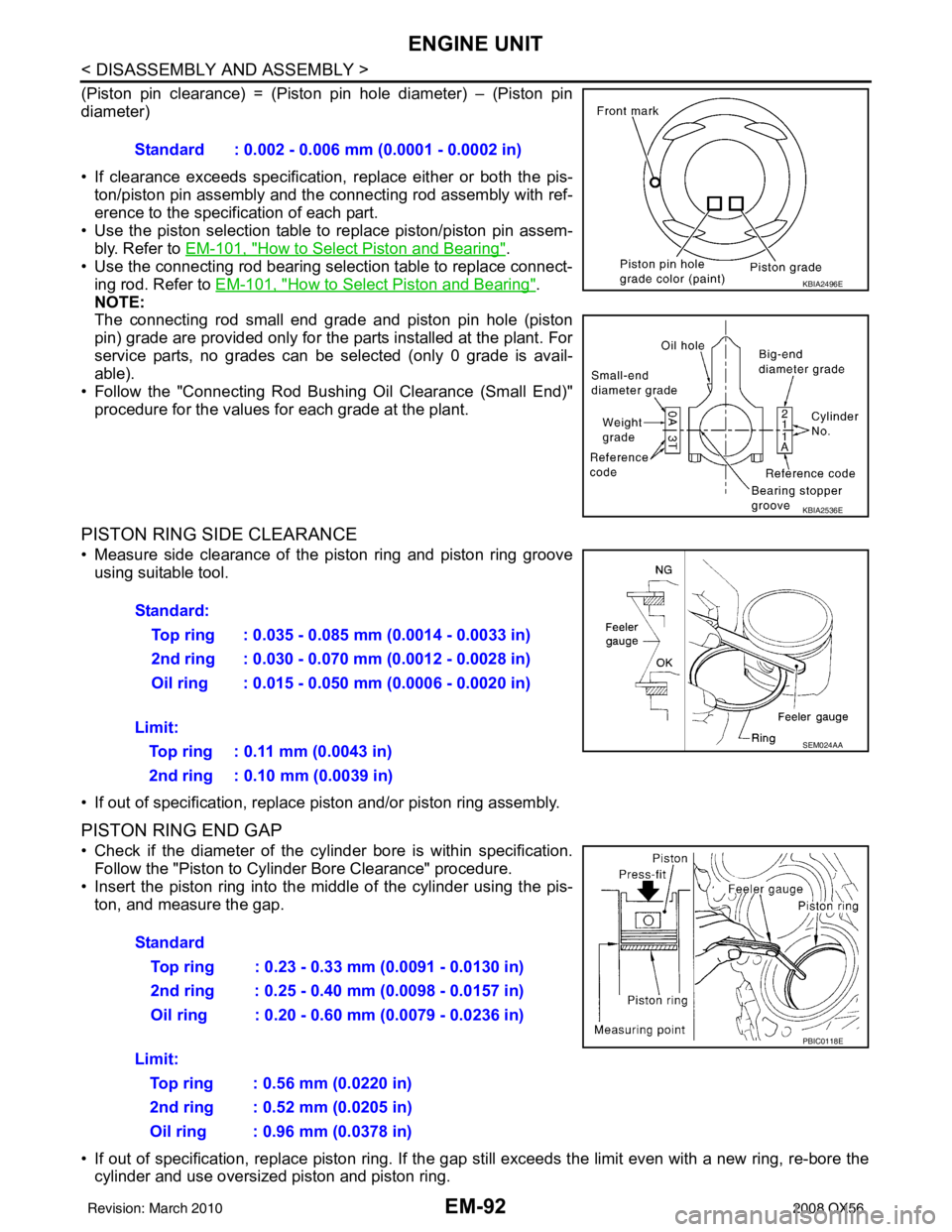
(Piston pin clearance) = (Piston pin hole diameter) – (Piston pin
diameter)
• If clearance exceeds specification, replace either or both the pis-
ton/piston pin assembly and the connecting rod assembly with ref-
erence to the specification of each part.
• Use the piston selection table to replace piston/piston pin assem-
bly. Refer to EM-101, "
How to Select Piston and Bearing".
• Use the connecting rod bearing selection table to replace connect- ing rod. Refer to EM-101, "
How to Select Piston and Bearing".
NOTE:
The connecting rod small end grade and piston pin hole (piston
pin) grade are provided only for the parts installed at the plant. For
service parts, no grades can be selected (only 0 grade is avail-
able).
• Follow the "Connecting Rod Bushing Oil Clearance (Small End)" procedure for the values for each grade at the plant.
PISTON RING SIDE CLEARANCE
• Measure side clearance of the piston ring and piston ring grooveusing suitable tool.
• If out of specification, replac e piston and/or piston ring assembly.
PISTON RING END GAP
• Check if the diameter of the cyli nder bore is within specification.
Follow the "Piston to Cylinder Bore Clearance" procedure.
• Insert the piston ring into the middle of the cylinder using the pis- ton, and measure the gap.
• If out of specification, replace pi ston ring. If the gap still exceeds the li mit even with a new ring, re-bore the
cylinder and use oversized piston and piston ring. Standard : 0.002 - 0.006 mm (0.0001 - 0.0002 in)
KBIA2496E
KBIA2536E
Standard:
Top ring : 0.035 - 0.085 mm (0.0014 - 0.0033 in)
2nd ring : 0.030 - 0.070 mm (0.0012 - 0.0028 in)
Oil ring : 0.015 - 0.050 mm (0.0006 - 0.0020 in)
Limit: Top ring : 0.11 mm (0.0043 in)
2nd ring : 0.10 mm (0.0039 in)
SEM024AA
Standard Top ring : 0.23 - 0.33 mm (0.0091 - 0.0130 in)
2nd ring : 0.25 - 0.40 mm (0.0098 - 0.0157 in)
Oil ring : 0.20 - 0.60 mm (0.0079 - 0.0236 in)
Limit: Top ring : 0.56 mm (0.0220 in)
2nd ring : 0.52 mm (0.0205 in)
Oil ring : 0.96 mm (0.0378 in)
PBIC0118E
Revision: March 2010 2008 QX56
Page 1896 of 4083
ENGINE UNITEM-93
< DISASSEMBLY AND ASSEMBLY >
C
DE
F
G H
I
J
K L
M A
EM
NP
O
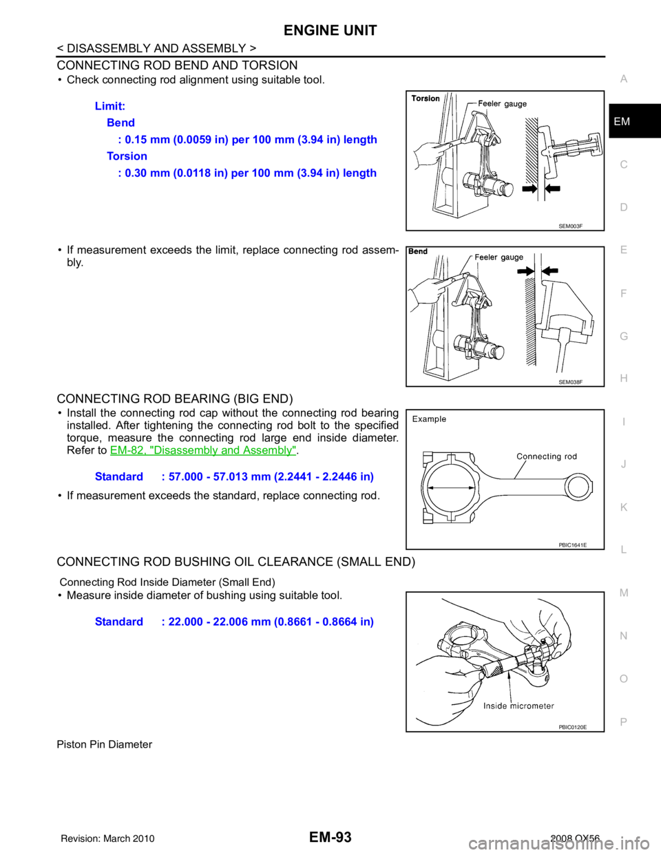
CONNECTING ROD BEND AND TORSION
• Check connecting rod alignment using suitable tool.
• If measurement exceeds the limi
t, replace connecting rod assem-
bly.
CONNECTING ROD BEARING (BIG END)
• Install the connecting rod cap without the connecting rod bearing installed. After tightening the connecting rod bolt to the specified
torque, measure the connecting rod large end inside diameter.
Refer to EM-82, "
Disassembly and Assembly".
• If measurement exceeds the standard, replace connecting rod.
CONNECTING ROD BUSHING OIL CLEARANCE (SMALL END)
Connecting Rod Inside Diameter (Small End)
• Measure inside diameter of bushing using suitable tool.
Piston Pin Diameter
Limit: Bend: 0.15 mm (0.0059 in) per 100 mm (3.94 in) length
To r s i o n : 0.30 mm (0.0118 in) per 100 mm (3.94 in) length
SEM003F
SEM038F
Standard : 57.000 - 57.013 mm (2.2441 - 2.2446 in)
PBIC1641E
Standard : 22.000 - 22.006 mm (0.8661 - 0.8664 in)
PBIC0120E
Revision: March 2010 2008 QX56
Page 1910 of 4083
HOW TO SELECT PISTON AND BEARINGEM-107
< DISASSEMBLY AND ASSEMBLY >
C
DE
F
G H
I
J
K L
M A
EM
NP
O
*: Always check with the Parts Department for the latest parts information.
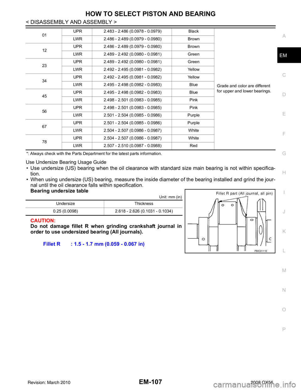
Use Undersize Bearing Usage Guide
• Use undersize (US) bearing when the oil clearance with
standard size main bearing is not within specifica-
tion.
• When using undersize (US) bearing, measure the inside di ameter of the bearing installed and grind the jour-
nal until the oil clearance falls within specification.
Bearing undersize table
Unit: mm (in)
CAUTION:
Do not damage fillet R when grinding crankshaft journal in
order to use undersized bearing (All journals).
01 UPR
2.483 - 2.486 (0.0978 - 0.0979) Black
Grade and color are different
for upper and lower bearings.
LWR
2.486 - 2.489 (0.0979 - 0.0980) Brown
12 UPR
2.486 - 2.489 (0.0979 - 0.0980) Brown
LWR 2.489 - 2.492 (0.0980 - 0.0981) Green
23 UPR
2.489 - 2.492 (0.0980 - 0.0981) Green
LWR 2.492 - 2.495 (0.0981 - 0.0982) Yellow
34 UPR
2.492 - 2.495 (0.0981 - 0.0982) Yellow
LWR 2.495 - 2.498 (0.0982 - 0.0983) Blue
45 UPR
2.495 - 2.498 (0.0982 - 0.0983) Blue
LWR 2.498 - 2.501 (0.0983 - 0.0985) Pink
56 UPR
2.498 - 2.501 (0.0983 - 0.0985) Pink
LWR 2.501 - 2.504 (0.0985 - 0.0986) Purple
67 UPR
2.501 - 2.504 (0.0985 - 0.0986) Purple
LWR 2.504 - 2.507 (0.0986 - 0.0987) White
78 UPR
2.504 - 2.507 (0.0986 - 0.0987) White
LWR 2.507 - 2.510 (0.0987 - 0.0988) Red
UndersizeThickness
0.25 (0.0098) 2.618 - 2.626 (0.1031 - 0.1034)
Fillet R : 1.5 - 1.7 mm (0.059 - 0.067 in)
PBIC0111E
Revision: March 2010 2008 QX56
Page 1920 of 4083
SERVICE DATA AND SPECIFICATIONS (SDS)EM-117
< SERVICE DATA AND SPECIFICATIONS (SDS)
C
DE
F
G H
I
J
K L
M A
EM
NP
O
*: Always check with the Parts Department for the latest parts information.
Undersize
Unit: mm (in)
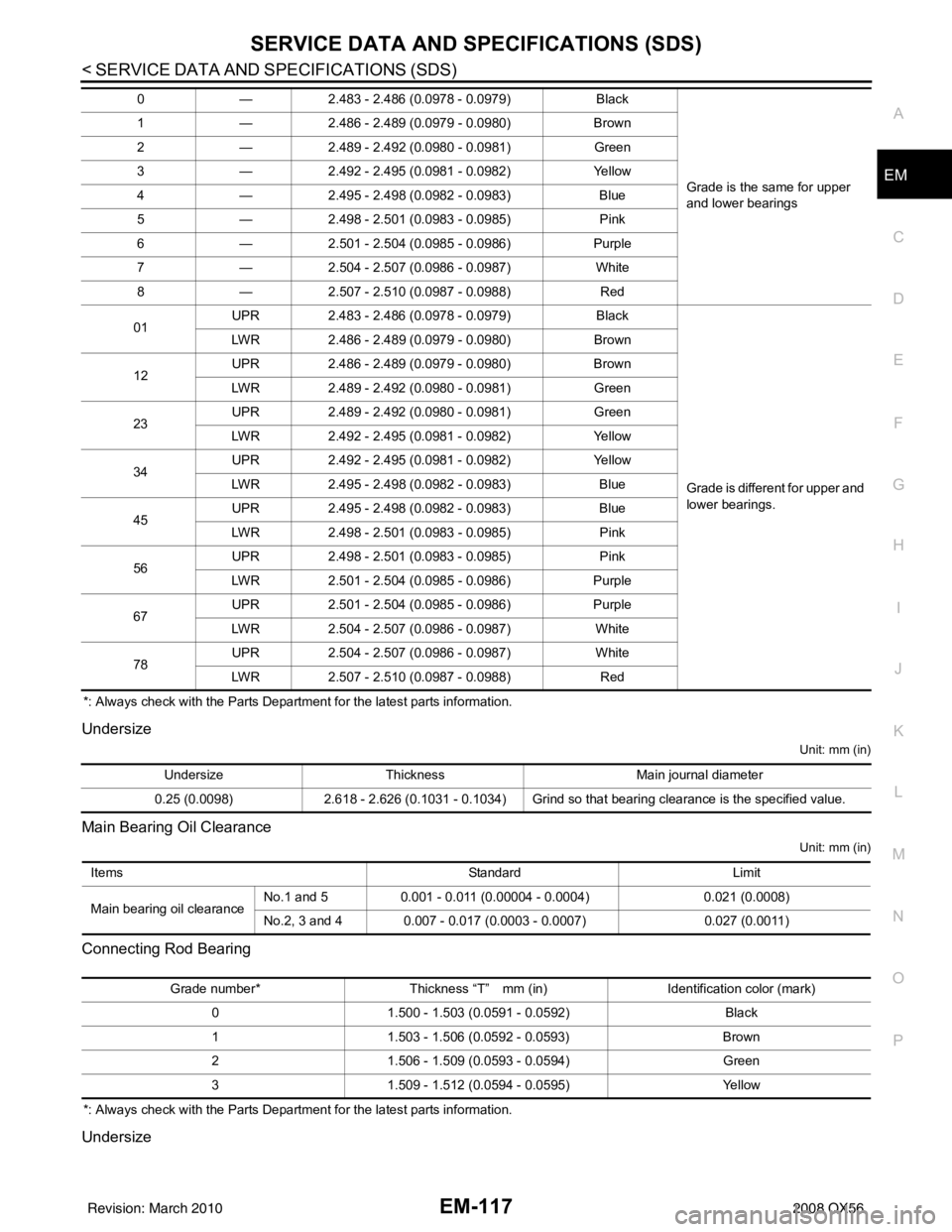
Main Bearing Oil Clearance
Unit: mm (in)
Connecting Rod Bearing
*: Always check with the Parts Department for the latest parts information.
Undersize
0
—2.483 - 2.486 (0.0978 - 0.0979) Black
Grade is the same for upper
and lower bearings
1
—2.486 - 2.489 (0.0979 - 0.0980) Brown
2 —2.489 - 2.492 (0.0980 - 0.0981) Green
3 —2.492 - 2.495 (0.0981 - 0.0982) Yellow
4 —2.495 - 2.498 (0.0982 - 0.0983) Blue
5 —2.498 - 2.501 (0.0983 - 0.0985) Pink
6 —2.501 - 2.504 (0.0985 - 0.0986) Purple
7 —2.504 - 2.507 (0.0986 - 0.0987) White
8 —2.507 - 2.510 (0.0987 - 0.0988) Red
01 UPR
2.483 - 2.486 (0.0978 - 0.0979) Black
Grade is different for upper and
lower bearings.
LWR
2.486 - 2.489 (0.0979 - 0.0980) Brown
12 UPR
2.486 - 2.489 (0.0979 - 0.0980) Brown
LWR 2.489 - 2.492 (0.0980 - 0.0981) Green
23 UPR
2.489 - 2.492 (0.0980 - 0.0981) Green
LWR 2.492 - 2.495 (0.0981 - 0.0982) Yellow
34 UPR
2.492 - 2.495 (0.0981 - 0.0982) Yellow
LWR 2.495 - 2.498 (0.0982 - 0.0983) Blue
45 UPR
2.495 - 2.498 (0.0982 - 0.0983) Blue
LWR 2.498 - 2.501 (0.0983 - 0.0985) Pink
56 UPR
2.498 - 2.501 (0.0983 - 0.0985) Pink
LWR 2.501 - 2.504 (0.0985 - 0.0986) Purple
67 UPR
2.501 - 2.504 (0.0985 - 0.0986) Purple
LWR 2.504 - 2.507 (0.0986 - 0.0987) White
78 UPR
2.504 - 2.507 (0.0986 - 0.0987) White
LWR 2.507 - 2.510 (0.0987 - 0.0988) Red
UndersizeThickness Main journal diameter
0.25 (0.0098) 2.618 - 2.626 (0.1031 - 0.1034) Grind so that bearing clearance is the specified value.
Items StandardLimit
Main bearing oil clearance No.1 and 5
0.001 - 0.011 (0.00004 - 0.0004) 0.021 (0.0008)
No.2, 3 and 4 0.007 - 0.017 (0.0003 - 0.0007) 0.027 (0.0011)
Grade number*Thickness “T” mm (in) Identification color (mark)
0 1.500 - 1.503 (0.0591 - 0.0592) Black
1 1.503 - 1.506 (0.0592 - 0.0593) Brown
2 1.506 - 1.509 (0.0593 - 0.0594) Green
3 1.509 - 1.512 (0.0594 - 0.0595) Yellow
Revision: March 2010 2008 QX56
Page 1924 of 4083
PRECAUTIONSEX-3
< PRECAUTION >
C
DE
F
G H
I
J
K L
M A
EX
NP
O
5. When the repair work is completed, return the ignition switch to the
″LOCK ″ position before connecting
the battery cables. (At this time, the steering lock mechanism will engage.)
6. Perform a self-diagnosis check of al l control units using CONSULT-III.
Precaution for Liquid GasketINFOID:0000000001538868
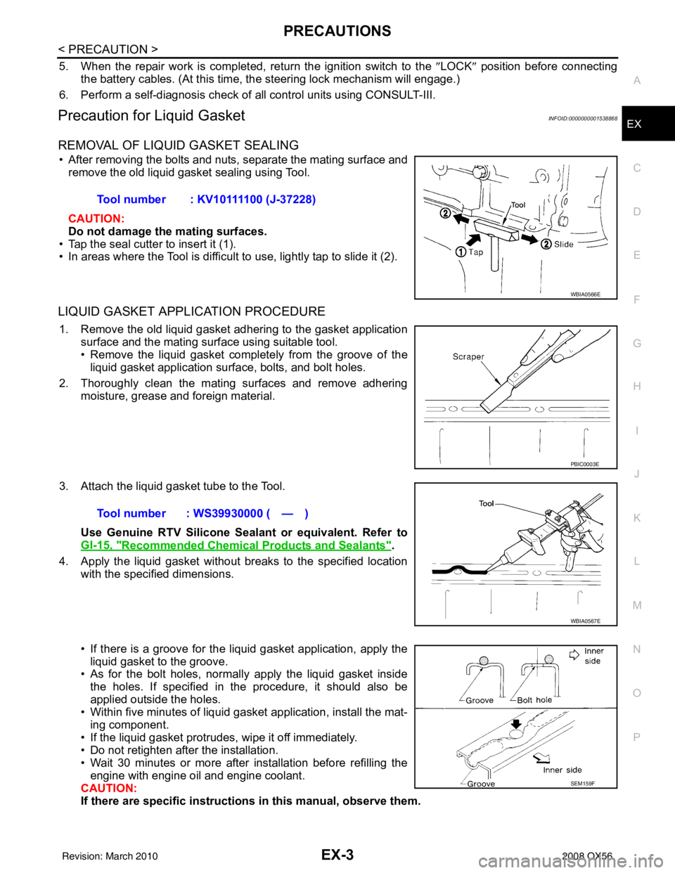
REMOVAL OF LIQUID GASKET SEALING
• After removing the bolts and nuts, separate the mating surface and
remove the old liquid gasket sealing using Tool.
CAUTION:
Do not damage the mating surfaces.
• Tap the seal cutter to insert it (1).
• In areas where the Tool is difficult to use, lightly tap to slide it (2).
LIQUID GASKET APPLICATION PROCEDURE
1. Remove the old liquid gasket adhering to the gasket application surface and the mating surface using suitable tool.
• Remove the liquid gasket completely from the groove of the
liquid gasket application surface, bolts, and bolt holes.
2. Thoroughly clean the mating surfaces and remove adhering moisture, grease and foreign material.
3. Attach the liquid gasket tube to the Tool. Use Genuine RTV Silicone Sealant or equivalent. Refer to
GI-15, "
Recommended Chemical Products and Sealants".
4. Apply the liquid gasket without breaks to the specified location with the specified dimensions.
• If there is a groove for the liquid gasket application, apply theliquid gasket to the groove.
• As for the bolt holes, normally apply the liquid gasket inside
the holes. If specified in the procedure, it should also be
applied outside the holes.
• Within five minutes of liquid gasket application, install the mat-
ing component.
• If the liquid gasket protrudes, wipe it off immediately.
• Do not retighten after the installation.
• Wait 30 minutes or more after installation before refilling the engine with engine oil and engine coolant.
CAUTION:
If there are specific instructions in this manual, observe them.
Tool number : KV10111100 (J-37228)
WBIA0566E
PBIC0003E
Tool number : WS39930000 ( — )
WBIA0567E
SEM159F
Revision: March 2010
2008 QX56
Page 2038 of 4083
EXL-110
< ON-VEHICLE REPAIR >
ADJUSTMENT AND INSPECTION
ON-VEHICLE REPAIR
ADJUSTMENT AND INSPECTION
HEADLAMP
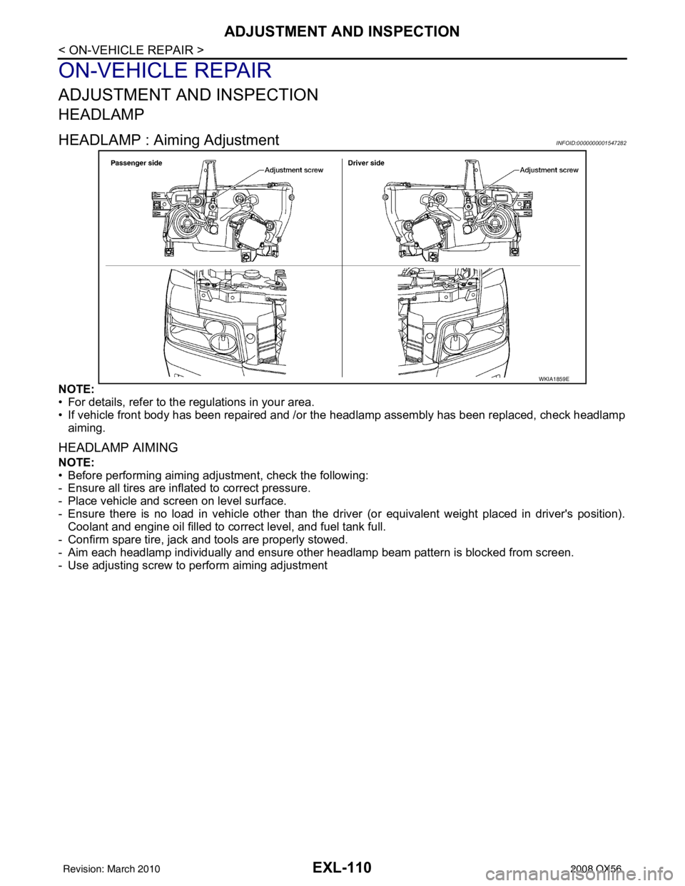
HEADLAMP : Aiming AdjustmentINFOID:0000000001547282
NOTE:
• For details, refer to the regulations in your area.
• If vehicle front body has been repaired and /or the headlamp assembly has been replaced, check headlamp
aiming.
HEADLAMP AIMING
NOTE:
• Before performing aiming adjustment, check the following:
- Ensure all tires are inflated to correct pressure.
- Place vehicle and screen on level surface.
- Ensure there is no load in vehicle other than the driver (or equivalent weight placed in driver's position).
Coolant and engine oil filled to correct level, and fuel tank full.
- Confirm spare tire, jack and tools are properly stowed.
- Aim each headlamp individually and ensure other headlamp beam pattern is blocked from screen.
- Use adjusting screw to perform aiming adjustment
WKIA1859E
Revision: March 2010 2008 QX56
Page 2056 of 4083
PRECAUTIONSEXT-3
< SERVICE INFORMATION >
C
DE
F
G H
I
J
L
M A
B
EXT
N
O P
5. When the repair work is completed, return the ignition switch to the ″LOCK ″ position before connecting
the battery cables. (At this time, the steering lock mechanism will engage.)
6. Perform a self-diagnosis check of al l control units using CONSULT-III.
Service NoticeINFOID:0000000001609843
• When removing or installing various parts, place a cloth or padding on the vehicle body to prevent scratches.
• Handle trim, molding, instruments, grille, etc. carefully during removing or installing. Be careful not to soil or
damage them.
• Apply sealing compound where necessary when installing parts.
• When applying sealing compound, be careful that the sealing compound does not protrude from parts.
• When replacing any metal parts (for example body outer panel, members, etc.), be sure to take rust preven-
tion measures.
Revision: March 2010 2008 QX56
Page 2093 of 4083
DRIVE SHAFTFAX-9
< REMOVAL AND INSTALLATION >
CEF
G H
I
J
K L
M A
B
FA X
N
O P
DRIVE SHAFT
Removal and InstallationINFOID:0000000001534458
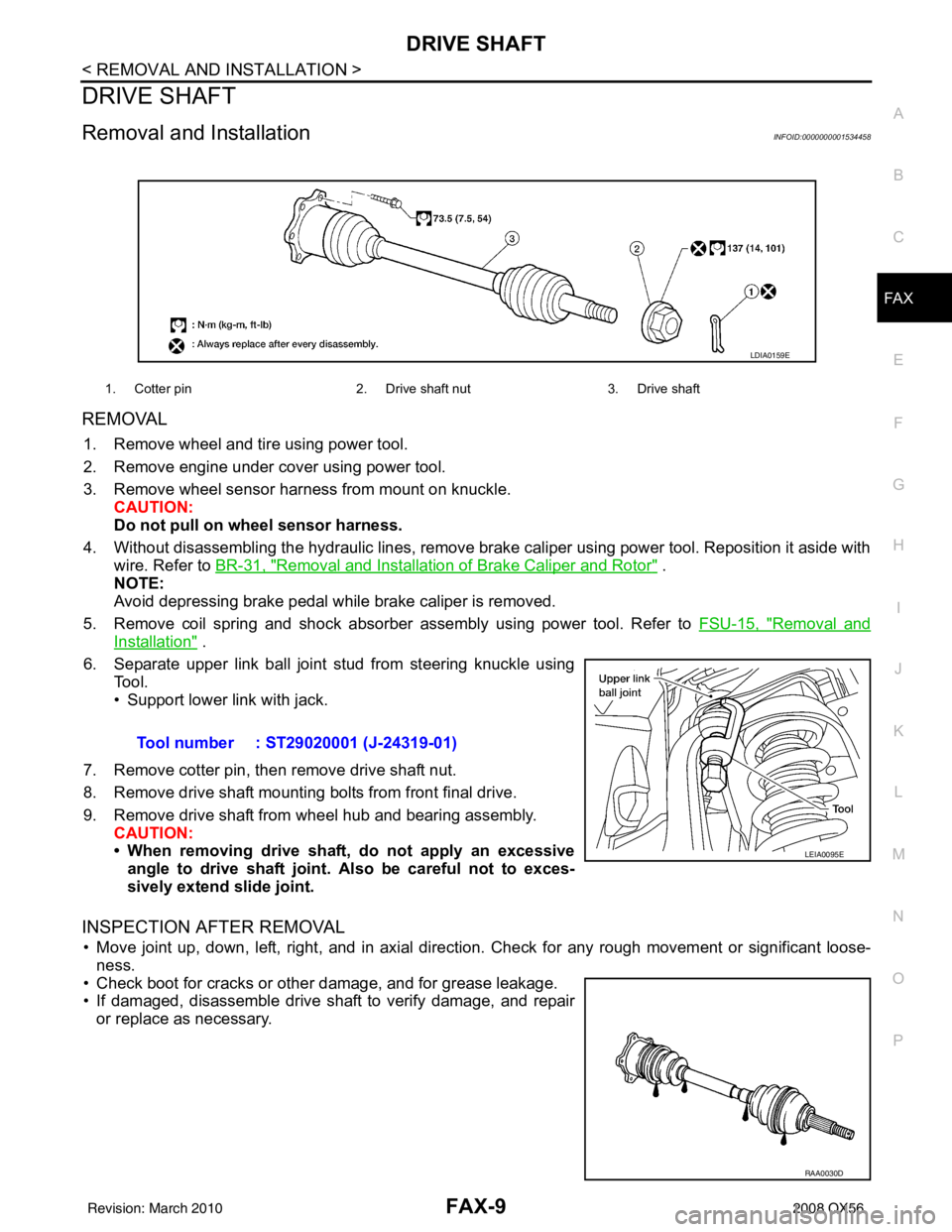
REMOVAL
1. Remove wheel and tire using power tool.
2. Remove engine under cover using power tool.
3. Remove wheel sensor harness from mount on knuckle. CAUTION:
Do not pull on wheel sensor harness.
4. Without disassembling the hydraulic lines, remove brake caliper using power tool. Reposition it aside with wire. Refer to BR-31, "
Removal and Installation of Brake Caliper and Rotor" .
NOTE:
Avoid depressing brake pedal while brake caliper is removed.
5. Remove coil spring and shock absorber assembly using power tool. Refer to FSU-15, "
Removal and
Installation" .
6. Separate upper link ball joint stud from steering knuckle using Tool.
• Support lower link with jack.
7. Remove cotter pin, then remove drive shaft nut.
8. Remove drive shaft mounting bolts from front final drive.
9. Remove drive shaft from wheel hub and bearing assembly. CAUTION:
• When removing drive shaf t, do not apply an excessive
angle to drive shaft joint. Also be careful not to exces-
sively extend slide joint.
INSPECTION AFTER REMOVAL
• Move joint up, down, left, right, and in axial directi on. Check for any rough movement or significant loose-
ness.
• Check boot for cracks or other damage, and for grease leakage.
• If damaged, disassemble drive shaft to verify damage, and repair or replace as necessary.
1. Cotter pin 2. Drive shaft nut3. Drive shaft
LDIA0159E
Tool number : ST29020001 (J-24319-01)
LEIA0095E
RAA0030D
Revision: March 2010 2008 QX56