Page 2245 of 4083
HA-40
< ON-VEHICLE REPAIR >
HIGH-PRESSURE FLEXIBLE HOSE
HIGH-PRESSURE FLEXIBLE HOSE
Removal and Installation for High-Pressure Flexible HoseINFOID:0000000001516656
REMOVAL
1. Remove the engine under cover.
2. Remove the front LH fender protector. Refer to EXT-23, "
Removal and Installation".
3. Remove the engine air cleaner and air ducts. Refer to EM-25, "
Removal and Installation".
4. Discharge the refrigerant. Refer to HA-20, "
HFC-134a (R-134a) Service Procedure".
5. Remove the high-pressure flexible hose. CAUTION:
Cap or wrap the joint of the pipe with suitable mate rial such as vinyl tape to avoid the entry of air.
INSTALLATION
Installation is in the reverse order of removal.
Refer to HA-29, "
Component".
CAUTION:
• Replace the O-ring of the high-pressure flexible hose with a new one, then apply compressor oil to it
when installing it.
• After charging refrigerant, check for leaks.
Revision: March 2010 2008 QX56
Page 2246 of 4083

HIGH-PRESSURE PIPEHA-41
< ON-VEHICLE REPAIR >
C
DE
F
G H
J
K L
M A
B
HA
N
O P
HIGH-PRESSURE PIPE
Removal and Installation for High-Pressure PipeINFOID:0000000001516657
REMOVAL
1. Remove the cowl top extension. Refer to EXT-18, "Removal and Installation".
2. Disconnect the battery negative terminal and positive battery terminal.
3. Reposition the IPDM E/R aside.
4. Remove the front right wheel and tire assembly. Refer to WT-48, "
Rotation".
5. Remove front right fender protector. Refer to EXT-23, "
Removal and Installation"
6. Position aside the front floor insulator.
7. Discharge the refrigerant. Refer to HA-20, "
HFC-134a (R-134a) Service Procedure".
8. Remove the low pressure pipe. Refer to HA-37, "
Removal and Installation for Low-Pressure Pipe".
9. Remove the high-pressure pipe. CAUTION:
Cap or wrap the joint of the pipe with suitable mate rial such as vinyl tape to avoid the entry of air.
INSTALLATION
Installation is in the reverse order of removal.
Refer to HA-29, "
Component".
CAUTION:
• Replace the O-ring of the high-pressure pipe with a new one, then apply compressor oil to it when
installing it.
• After charging refrigerant, check for leaks.
Removal and Installation for Rear High- and Low-Pressure A/C and Heater Core Pipes
INFOID:0000000002975448
REMOVAL
1. Discharge the refrigerant from the A/C system. Refer to HA-20, "HFC-134a (R-134a) Service Procedure".
2. Drain the coolant from the engine cooling system. Refer to CO-11, "
Changing Engine Coolant".
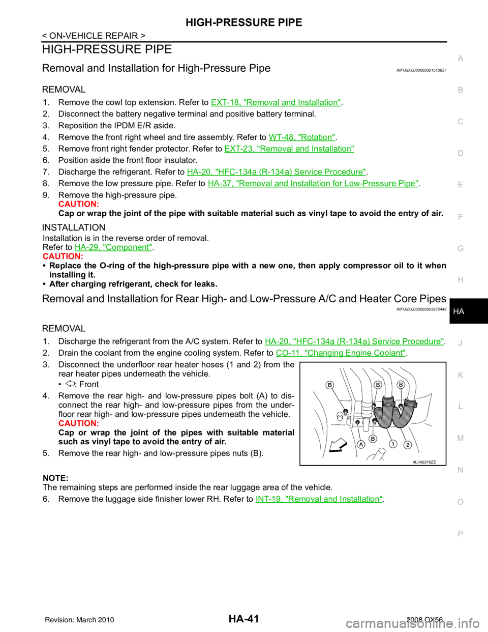
3. Disconnect the underfloor rear heater hoses (1 and 2) from the rear heater pipes underneath the vehicle.
• : Front
4. Remove the rear high- and low-pressure pipes bolt (A) to dis- connect the rear high- and low-pressure pipes from the under-
floor rear high- and low-pressure pipes underneath the vehicle.
CAUTION:
Cap or wrap the joint of the pipes with suitable material
such as vinyl tape to avo id the entry of air.
5. Remove the rear high- and low-pressure pipes nuts (B).
NOTE:
The remaining steps are performed inside the rear luggage area of the vehicle.
6. Remove the luggage side finisher lower RH. Refer to INT-19, "
Removal and Installation".
ALIIA0216ZZ
Revision: March 2010 2008 QX56
Page 2248 of 4083

HIGH-PRESSURE PIPEHA-43
< ON-VEHICLE REPAIR >
C
DE
F
G H
J
K L
M A
B
HA
N
O P
• Replace the O-rings on the rear high- and low-pr essure A/C pipes with a new ones, then apply com-
pressor oil to them for installation.
• After charging the refrigerant, check for leaks.
Removal and Installation for Underfloor Rear High- and Lo w-Pressure A/C and Heater
Core Pipes
INFOID:0000000002975449
REMOVAL
1. Drain the engine coolant. Refer to CO-11, "Changing Engine Coolant".
2. Disconnect the battery negative terminal.
3. Disconnect the generator harness.
4. Discharge the refrigerant. Refer to HA-20, "
HFC-134a (R-134a) Service Procedure".
5. Remove the front and rear bumper fascia. Refer to EXT-13, "
Removal and Installation" (front), EXT-15,
"Removal and Installation" (rear).
6. Reposition the front fender protector out of the way. Refer to EXT-23, "
Removal and Installation".
7. Disconnect the chassis harness connector.
8. Remove the spare wheel and tire.
9. Remove the tailpipe and tailpipe hanger bracket. Refer to EX-6, "
Removal and Installation".
10. Remove the seatbelt latch anchor. Refer to EX-6, "
Removal and Installation".
11. Remove the front floor heat shield.
12. Disconnect each end of the underfloor rear high- and low-pressure A/C and heater core pipes. Refer to HA-29, "
Component".
CAUTION:
Cap or wrap the joint of the pipes with suitable material such as viny l tape to avoid the entry of air.
13. Set two suitable jacks at the RH body mount points to support the vehicle body when it is separated from the RH side of the frame.
14. Remove the RH body mount bolts. Refer to BRM-2, "
Body Mounting".
15. Use the vehicle hoist to lower the RH side of the frame from the RH side of the body [approximately 305 mm (12 in)] until there is sufficient clearance to remove the underfloor rear high- and low-pressure A/C
and heater core pipes from between the body and the frame.
16. Remove the underfloor rear high- and low-pressure A/C and heater core pipes from the back of the vehi- cle.
INSTALLATION
Installation is in the reverse order of removal.
CAUTION:
• Replace the O-rings of the underfloor rear high - and low-pressure A/C and heater core pipes with
new ones, then apply compressor oil to them for installation.
• After charging refrigerant, check for leaks.
Revision: March 2010 2008 QX56
Page 2249 of 4083

HA-44
< ON-VEHICLE REPAIR >
CONDENSER
CONDENSER
Removal and Installation for CondenserINFOID:0000000001516658
REMOVAL
1. Discharge the refrigerant. Refer to HA-20, "HFC-134a (R-134a) Service Procedure".
2. Remove the radiator. Refer to CO-15, "
Removal and Installation".
CAUTION:
Be careful not to damage the core su rface of the condenser and the radiator.
3. Disconnect the high-pressure flexible hose and the high-pressure pipe from the condenser. CAUTION:
Cap or wrap the joint of the pipe with suitable ma terial such as vinyl tape to avoid the entry of air.
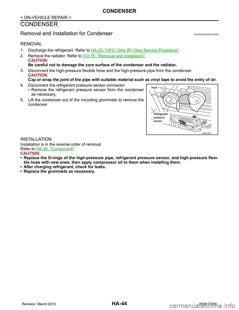
4. Disconnect the refrigerant pressure sensor connector. • Remove the refrigerant pressure sensor from the condenseras necessary.
5. Lift the condenser out of the mounting grommets to remove the condenser.
INSTALLATION
Installation is in the reverse order of removal.
Refer to HA-29, "
Component".
CAUTION:
• Replace the O-rings of the high-pressure pipe, refrigerant pressure sensor, and high-pressure flexi- ble hose with new ones, then apply compr essor oil to them when installing them.
• After charging refrigerant, check for leaks.
• Replace the grommets as necessary.
LJIA0145E
Revision: March 2010 2008 QX56
Page 2251 of 4083
HA-46
< ON-VEHICLE REPAIR >
REFRIGERANT PRESSURE SENSOR
REFRIGERANT PRESSURE SENSOR
Removal and Installation for Refrigerant Pressure SensorINFOID:0000000001516660
REMOVAL
1. Discharge the refrigerant. Refer to HA-20, "HFC-134a (R-134a) Service Procedure".
2. Disconnect the refrigerant pressure sensor electrical connector and remove the refrigerant pressure sensor from the condenser.
CAUTION:
Be careful not to damage the condenser fins.
INSTALLATION
Installation is in the reverse order of removal.
Refer to HA-29, "
Component".
CAUTION:
• Be careful not to damage the condenser fins.
• Replace the O-ring of the refriger ant pressure sensor with a new one, then apply compressor oil to it
when installing it.
• After charging refrigerant, check for leaks.
LJIA0145E
Revision: March 2010 2008 QX56
Page 2252 of 4083
EXPANSION VALVEHA-47
< ON-VEHICLE REPAIR >
C
DE
F
G H
J
K L
M A
B
HA
N
O P
EXPANSION VALVE
Removal and Installation for Front Expansion ValveINFOID:0000000001516661
REMOVAL
1. Discharge the refrigerant. Refer to HA-20, "HFC-134a (R-134a) Service Procedure".
2. Remove the front evaporator. Refer to VTL-35, "
Removal and Installation for Front Evaporator".
3. Remove the cooler grommet.
4. Remove the expansion valve.
INSTALLATION
Installation is in the reverse order of removal.
CAUTION:
• Replace the O-rings on the A/C refrigerant pipes with new ones, th en apply compressor oil to them
when installing them.
• After charging refrigerant, check for leaks.
WJIA0582E
Expansion valve bolts : 4 N·m (0.41 kg-m, 35 in-lb)
A/C refrigerant pipe to expansion valve bolt : Refer to HA-29, "
Component".
Revision: March 2010 2008 QX56
Page 2305 of 4083
![INFINITI QX56 2008 Factory Service Manual HAC-52
< COMPONENT DIAGNOSIS >[AUTOMATIC AIR CONDITIONER]
BLOWER MOTOR CONTROL SYSTEM
Check 20A fuses [No. 24 and 27 (Located in the fuse and fusible link box)]. For fuse layout. Refer to
PG-70,
"Ter INFINITI QX56 2008 Factory Service Manual HAC-52
< COMPONENT DIAGNOSIS >[AUTOMATIC AIR CONDITIONER]
BLOWER MOTOR CONTROL SYSTEM
Check 20A fuses [No. 24 and 27 (Located in the fuse and fusible link box)]. For fuse layout. Refer to
PG-70,
"Ter](/manual-img/42/57030/w960_57030-2304.png)
HAC-52
< COMPONENT DIAGNOSIS >[AUTOMATIC AIR CONDITIONER]
BLOWER MOTOR CONTROL SYSTEM
Check 20A fuses [No. 24 and 27 (Located in the fuse and fusible link box)]. For fuse layout. Refer to
PG-70,
"Terminal Arrangement".
Is the inspection result normal?
YES >> GO TO 2.
NO >> GO TO 7.
2.CHECK FRONT BLOWER MOTOR POWER SUPPLY CIRCUIT
1. Turn ignition switch OFF.
2. Disconnect front blower motor connector.
3. Turn ignition switch ON.
4. Press the A/C switch.
5. Press the front blower control "+" switch to maximum speed.
6. Check voltage between front blower motor harness connector M62 terminal 2 and ground.
Is the inspection result normal?
YES >> GO TO 10.
NO >> GO TO 3.
3.CHECK FRONT BLOWER MOTOR RELAY (S WITCH SIDE) POWER SUPPLY CIRCUIT
1. Turn ignition switch OFF.
2. Disconnect front blower motor relay.
3. Check voltage between front blower motor relay harness con- nector M107 terminal 5 and ground.
Is the inspection result normal?
YES >> GO TO 4.
NO >> Repair harness or connector.
4.CHECK FRONT BLOWER MOTOR RELAY
Turn ignition switch OFF.
Check front blower motor relay. Refer to HAC-54, "
Front Blower Motor Component Inspection".
Is the inspection result normal?
YES >> GO TO 5.
NO >> Replace front blower motor relay.
5.CHECK FRONT BLOWER MOTOR RELA Y (SWITCH SIDE) CIRCUIT FOR OPEN
Check continuity between front blower motor relay harness connec-
tor M107 terminal 3 and front blower motor harness connector M62
terminal 2.
Is the inspection result normal?
YES >> GO TO 6.
NO >> Repair harness or connector.
6.CHECK FRONT BLOWER MOTOR RE LAY (COIL SIDE) POWER SUPPLY
Fuses are good.
2 - Ground
: Battery voltage
WJIA1331E
5 - Ground: Battery voltage
WJIA1886E
3 - 2 : Continuity should exist.
WJIA1360E
Revision: March 2010 2008 QX56
Page 2308 of 4083
BLOWER MOTOR CONTROL SYSTEMHAC-55
< COMPONENT DIAGNOSIS > [AUTOMATIC AIR CONDITIONER]
C
D
E
F
G H
J
K L
M A
B
HAC
N
O P
Check continuity between terminals by supplying 12 volts and
ground to coil side terminals of relay.
Front Blower Motor
Confirm smooth rotation of the blower motor.
• Ensure that there are no foreign particles inside the blower unit.
• Apply 12 volts to terminal 2 and ground to terminal 1 and verify that the motor operates freely and quietly.
Rear Blower Motor DescriptionINFOID:0000000001679799
SYSTEM DESCRIPTION
Component Parts
Rear blower speed control system components are:
• A/C auto amp.
• A/C and AV switch assembly
• Rear air control (front)
• Rear air control (rear)
• Variable blower control (rear)
• Rear blower motor
• Rear blower motor relay
WJIA1401E
WJIA1508E
Revision: March 2010 2008 QX56