2008 INFINITI QX56 blower motor rear
[x] Cancel search: blower motor rearPage 2213 of 4083

HA-8
< PRECAUTION >
PRECAUTIONS
Rear A/C
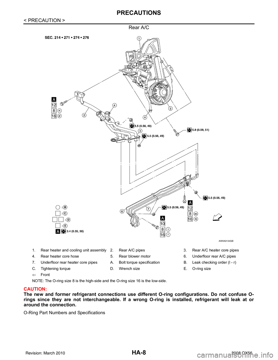
CAUTION:
The new and former refrigerant connections use different O-ring configurations. Do not confuse O-
rings since they are not interchangeable. If a wrong O-ring is installed, refrigerant will leak at or
around the connection.
O-Ring Part Numbers and Specifications
AWIIA0134GB
1. Rear heater and cooling unit assembly 2. Rear A/C pipes 3. Rear A/C heater core pipes
4. Rear heater core hose 5. Rear blower motor6. Underfloor rear A/C pipes
7. Underfloor rear heater core pipes A. Bolt torque specification B. Leak checking order (l - r)
C. Tightening torque D. Wrench sizeE. O-ring size
⇐ Front
NOTE: The O-ring size 8 is the high-side and the O-ring size 16 is the low-side.
Revision: March 2010 2008 QX56
Page 2235 of 4083

HA-30
< ON-VEHICLE REPAIR >
REFRIGERATION SYSTEM
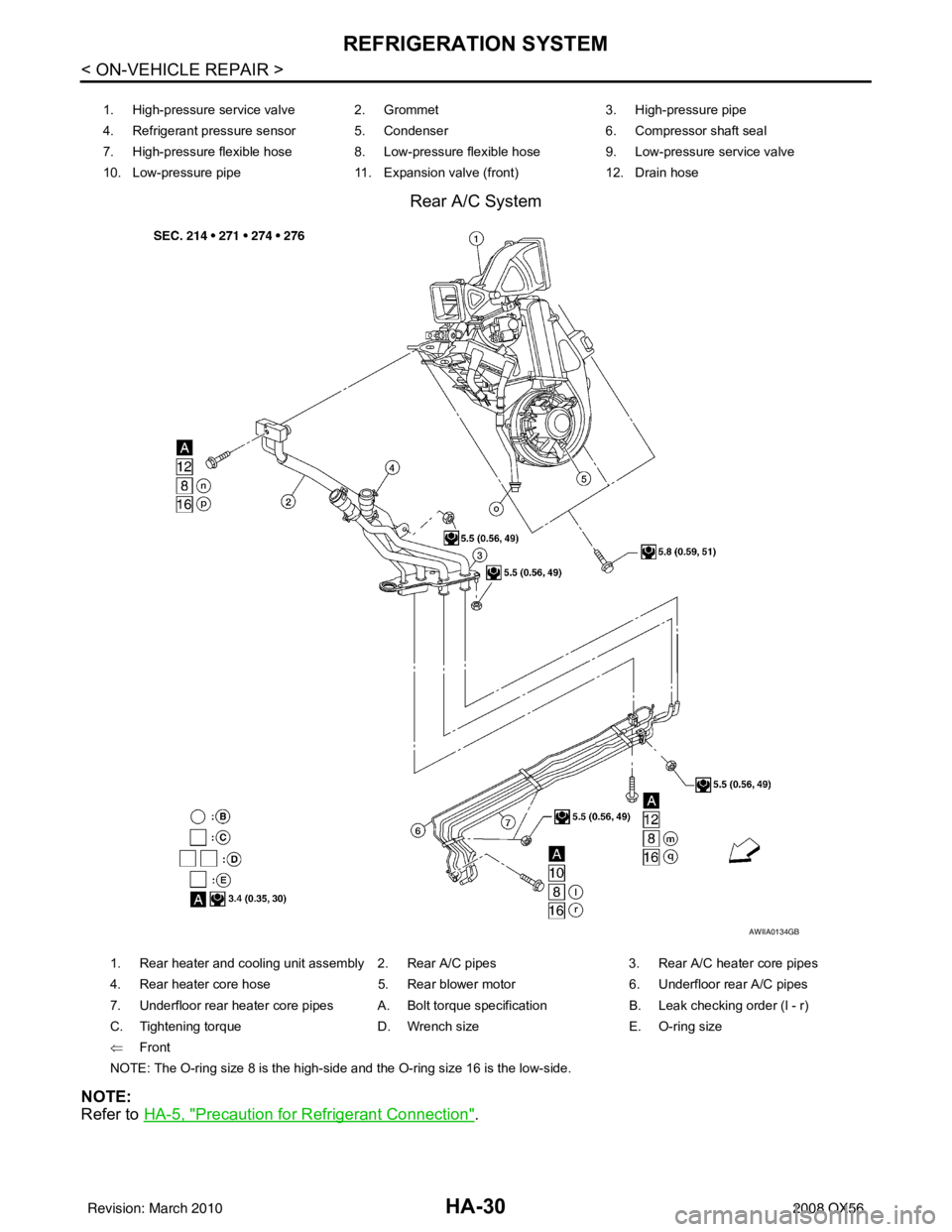
Rear A/C System
NOTE:
Refer to HA-5, "
Precaution for Refrigerant Connection".
1. High-pressure service valve 2. Grommet 3. High-pressure pipe
4. Refrigerant pressure sensor 5. Condenser 6. Compressor shaft seal
7. High-pressure flexible hose 8. Low-pressure flexible hose 9. Low-pressure service valve
10. Low-pressure pipe 11. Expansion valve (front)12. Drain hose
AWIIA0134GB
1. Rear heater and cooling unit assembly 2. Rear A/C pipes 3. Rear A/C heater core pipes
4. Rear heater core hose 5. Rear blower motor6. Underfloor rear A/C pipes
7. Underfloor rear heater core pipes A. Bolt torque specification B. Leak checking order (l - r)
C. Tightening torque D. Wrench sizeE. O-ring size
⇐ Front
NOTE: The O-ring size 8 is the high-side and the O-ring size 16 is the low-side.
Revision: March 2010 2008 QX56
Page 2243 of 4083

HA-38
< ON-VEHICLE REPAIR >
LOW-PRESSURE PIPE
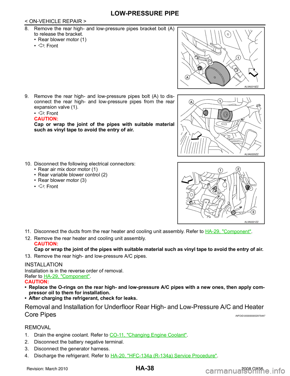
8. Remove the rear high- and low-pressure pipes bracket bolt (A)to release the bracket.
• Rear blower motor (1)
• : Front
9. Remove the rear high- and low-pressure pipes bolt (A) to dis- connect the rear high- and low-pressure pipes from the rear
expansion valve (1).
• : Front
CAUTION:
Cap or wrap the joint of the pipes with suitable material
such as vinyl tape to avoid the entry of air.
10. Disconnect the following electrical connectors: • Rear air mix door motor (1)
• Rear variable blower control (2)
• Rear blower motor (3)
• : Front
11. Disconnect the ducts from the rear heater and cooling unit assembly. Refer to HA-29, "
Component".
12. Remove the rear heater and cooling unit assembly. CAUTION:
Cap or wrap the joint of the pipes with suitable material such as viny l tape to avoid the entry of air.
13. Remove the rear high- and low-pressure A/C pipes.
INSTALLATION
Installation is in the reverse order of removal.
Refer to HA-29, "
Component".
CAUTION:
• Replace the O-rings on the rear high- and low-pr essure A/C pipes with a new ones, then apply com-
pressor oil to them for installation.
• After charging the refrigerant, check for leaks.
Removal and Installati on for Underfloor Rear High- and Low-Pressure A/C and Heater
Core Pipes
INFOID:0000000002975447
REMOVAL
1. Drain the engine coolant. Refer to CO-11, "Changing Engine Coolant".
2. Disconnect the battery negative terminal.
3. Disconnect the generator harness.
4. Discharge the refrigerant. Refer to HA-20, "
HFC-134a (R-134a) Service Procedure".
ALIIA0219ZZ
ALIIA0220ZZ
ALIIA0221ZZ
Revision: March 2010 2008 QX56
Page 2247 of 4083

HA-42
< ON-VEHICLE REPAIR >
HIGH-PRESSURE PIPE
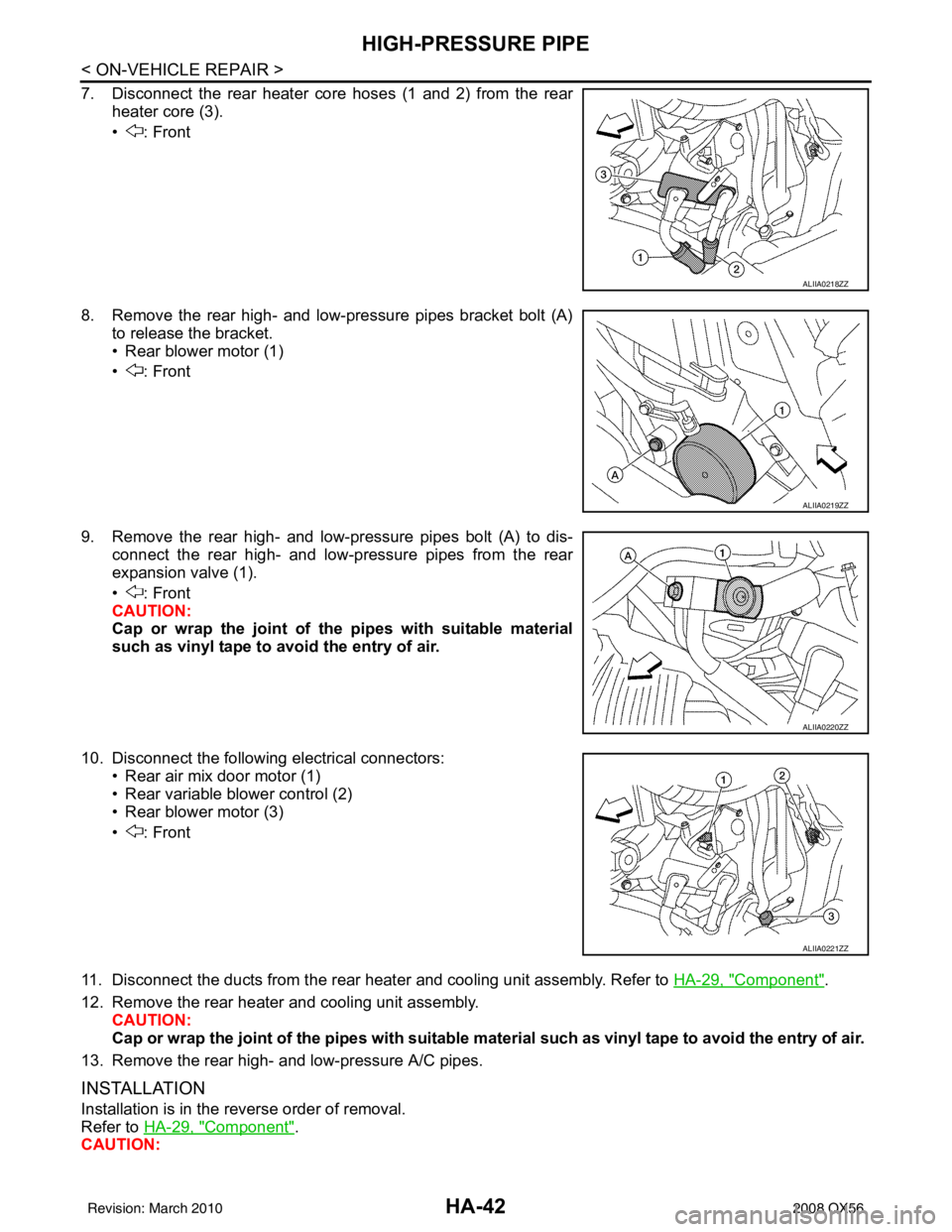
7. Disconnect the rear heater core hoses (1 and 2) from the rearheater core (3).
• : Front
8. Remove the rear high- and low-pressure pipes bracket bolt (A) to release the bracket.
• Rear blower motor (1)
• : Front
9. Remove the rear high- and low-pressure pipes bolt (A) to dis- connect the rear high- and low-pressure pipes from the rear
expansion valve (1).
• : Front
CAUTION:
Cap or wrap the joint of the pipes with suitable material
such as vinyl tape to avoid the entry of air.
10. Disconnect the following electrical connectors: • Rear air mix door motor (1)
• Rear variable blower control (2)
• Rear blower motor (3)
• : Front
11. Disconnect the ducts from the rear heater and cooling unit assembly. Refer to HA-29, "
Component".
12. Remove the rear heater and cooling unit assembly. CAUTION:
Cap or wrap the joint of the pipes with suitable material such as viny l tape to avoid the entry of air.
13. Remove the rear high- and low-pressure A/C pipes.
INSTALLATION
Installation is in the reverse order of removal.
Refer to HA-29, "
Component".
CAUTION:
ALIIA0218ZZ
ALIIA0219ZZ
ALIIA0220ZZ
ALIIA0221ZZ
Revision: March 2010 2008 QX56
Page 2254 of 4083

HAC-1
VENTILATION, HEATER & AIR CONDITIONER
C
DE
F
G H
J
K L
M
SECTION HAC
A
B
HAC
N
O P
CONTENTS
HEATER & AIR CONDITIONING CONTROL SYSTEM
AUTOMATIC AIR CONDITIONER
BASIC INSPECTION ....... .............................
3
DIAGNOSIS AND REPAIR WORKFLOW ..... .....3
How to Perform Trouble Diagnosis For Quick And
Accurate Repair ........................................................
3
INSPECTION AND ADJUSTMENT ................ .....4
Operational Check (Front) ................................... ......4
Operational Check (Rear) .........................................5
FUNCTION DIAGNOSIS ...............................7
FUNCTION INFORMATION ........................... .....7
Component Part Location ................................... ......7
Symptom Table .........................................................9
REFRIGERATION SYSTEM ..............................11
Refrigerant Cycle ................................................ ....11
Refrigerant System Protection ................................11
AUTOMATIC AIR CONDITIONER SYSTEM . ....12
Control System Diagram ..................................... ....12
Control System Description .....................................12
Discharge Air Flow (Front) ......................................15
Discharge Air Flow (Rear) .......................................15
Switches And Their Control Function (Front) ..........17
Switches And Their Control Function (Rear) ...........18
CAN COMMUNICATION SYSTEM ....................19
System Description ............................................. ....19
DIAGNOSIS SYSTEM (HVAC) ..........................20
CONSULT-III Function (HVAC) ........................... ....20
DIAGNOSIS SYSTEM (BCM) ............................21
CONSULT-III Function (BCM) ............................. ....21
SELF-DIAGNOSIS FUNCTION ..........................22
A/C Auto Amp. Self-Diagnosis ................................22
A/C and AV Switch Asse mbly Self-Diagnosis .........22
A/C System Self-Diagnosis Code Chart .............. ....23
COMPONENT DIAGNOSIS .........................24
MODE DOOR MOTOR ......................................24
System Description .............................................. ....24
Mode Door Motor (Front) Component Function
Check ......................................................................
25
Mode Door Motor (Front) Diagnosis Procedure ......26
AIR MIX DOOR MOTOR ...................................30
System Description ..................................................30
Air Mix Door Motor Component Function Check .....31
Air Mix Door Motor (Driver) Diagnosis Procedure ....32
Air Mix Door Motor (Passenger) Diagnosis Proce-
dure .........................................................................
35
INTAKE DOOR MOTOR ...................................40
System Description ..................................................40
Intake Door Motor Component Function Check ......41
Intake Door Motor Diagnosis Procedure .................42
DEFROSTER DOOR MOTOR CIRCUIT ...........44
System Description ..................................................44
Defroster Door Motor Component Function Check
....
45
Defroster Door Motor Diagnosis Procedure ............45
BLOWER MOTOR CONTROL SYSTEM ..........49
System Description ..................................................49
Front Blower Motor Component Function Check ....50
Front Blower Motor Diagnosis Procedure ................51
Front Blower Motor Component Inspection .............54
Rear Blower Motor Description ................................55
Rear Blower Motor Component Function Check .....56
Rear Air Control (Front) Diagnosis Procedure #1 ....57
Rear Air Control (Rear) Diagnosis Procedure #2 ....58
Rear Blower Motor Component Inspection ..............59
REAR AIR CONTROL SYSTEM .......................61
Rear Air Control System Description .......................61
Rear Air Control Component Function Check .........61
Air Mix Door Motor (Rear) Diagnosis Procedure .....62
Mode Door Motor (Rear) Diagnosis Procedure .......66
Revision: March 2010 2008 QX56
Page 2258 of 4083
![INFINITI QX56 2008 Factory Service Manual INSPECTION AND ADJUSTMENTHAC-5
< BASIC INSPECTION > [AUTOMATIC AIR CONDITIONER]
C
D
E
F
G H
J
K L
M A
B
HAC
N
O P
If NG, listen for sound of air mix door motor operat ion. If OK, go to trouble diagnos INFINITI QX56 2008 Factory Service Manual INSPECTION AND ADJUSTMENTHAC-5
< BASIC INSPECTION > [AUTOMATIC AIR CONDITIONER]
C
D
E
F
G H
J
K L
M A
B
HAC
N
O P
If NG, listen for sound of air mix door motor operat ion. If OK, go to trouble diagnos](/manual-img/42/57030/w960_57030-2257.png)
INSPECTION AND ADJUSTMENTHAC-5
< BASIC INSPECTION > [AUTOMATIC AIR CONDITIONER]
C
D
E
F
G H
J
K L
M A
B
HAC
N
O P
If NG, listen for sound of air mix door motor operat ion. If OK, go to trouble diagnosis procedure for HAC-109,
"Component Function Check". If air mix door motor appears to be malfunctioning, go to HAC-31, "Air Mix Door
Motor Component Function Check".
If OK, continue the check.
CHECKING TEMPERATURE INCREASE
1. Rotate temperature control dial clockwise (drive or passenger) until 32 °C (90° F) is displayed.
2. Check for hot air at appropriate discharge air outlets.
If NG, listen for sound of air mix door motor operat ion. If OK, go to trouble diagnosis procedure for HAC-117,
"Component Function Check". If air mix door motor appears to be malfunctioning, go to HAC-31, "Air Mix Door
Motor Component Function Check".
If OK, continue with next check.
CHECK A/C SWITCH
1. Press A/C switch when AUTO switch is ON, or in manual mode.
2. A/C switch indicator will turn ON. • Confirm that the compressor clutch engages (sound or visual inspection).
NOTE:
If current mode setting is DEF or D/F, compre ssor clutch will already be engaged and cannot be turned off.
If NG, go to trouble diagnosis procedure for HAC-72, "
Magnet Clutch Diagnosis Procedure".
If OK, continue with next check.
CHECKING AUTO MODE
1. Press AUTO switch.
2. Display should indicate AUTO.
• If ambient temperature is warm, and selected temperat ure is cool, confirm that the compressor clutch
engages (sound or visual inspection). (Discharge air and blower speed will depend on ambient, in-vehi-
cle, and set temperatures.)
If NG, go to trouble diagnosis procedure for HAC-89, "
A/C Auto Amp Power and Ground Diagnosis Proce-
dure", then if necessary, trouble diagnosis procedure for HAC-72, "Magnet Clutch Diagnosis Procedure".
If all operational checks are OK (symptom cannot be duplicated), go to malfunction Simulation Tests in HAC-
3, "How to Perform Trouble Diagnosis For Quick And Accurate Repair" and perform tests as outlined to simu-
late driving conditions environment. If symptom appears. Refer to HAC-108, "
SymptomMatrixChart", and
perform applicable troubl e diagnosis procedures.
Operational Check (Rear)INFOID:0000000001679765
The purpose of the operational check is to confirm that the system operates properly.
CHECKING REAR BLOWER MOTOR
1. Turn the ignition switch ON.
2. Rotate rear air control (front) blower control dial to low speed.
3. Rotate the blower control dial clockwise and continue checking blower speed until all speeds are checked.
4. Leave blower on maximum speed.
5. Press the REAR CTRL switch from the rear air control (front).
6. Rotate rear air control (rear) blower control dial to low speed.
7. Rotate the blower control dial clockwise and continue checking blower speed until all speeds are checked.
8. Leave blower on maximum speed.
If NG, go to trouble diagnosis procedure for HAC-56, "
Rear Blower Motor Component Function Check".
If OK, continue with next check.
CHECKING REAR DISCHARGE AIR
Conditions : Engine running and at normal operating temperature
Revision: March 2010 2008 QX56
Page 2262 of 4083
![INFINITI QX56 2008 Factory Service Manual FUNCTION INFORMATIONHAC-9
< FUNCTION DIAGNOSIS > [AUTOMATIC AIR CONDITIONER]
C
D
E
F
G H
J
K L
M A
B
HAC
N
O P
REAR PASSENGER COMPARTMENT
Symptom TableINFOID:0000000001679767
1. Rear blower control (r INFINITI QX56 2008 Factory Service Manual FUNCTION INFORMATIONHAC-9
< FUNCTION DIAGNOSIS > [AUTOMATIC AIR CONDITIONER]
C
D
E
F
G H
J
K L
M A
B
HAC
N
O P
REAR PASSENGER COMPARTMENT
Symptom TableINFOID:0000000001679767
1. Rear blower control (r](/manual-img/42/57030/w960_57030-2261.png)
FUNCTION INFORMATIONHAC-9
< FUNCTION DIAGNOSIS > [AUTOMATIC AIR CONDITIONER]
C
D
E
F
G H
J
K L
M A
B
HAC
N
O P
REAR PASSENGER COMPARTMENT
Symptom TableINFOID:0000000001679767
1. Rear blower control (rear) 2. Rear mode switch (rear)3. Rear temperature control (rear)
4. Rear blower motor B134 5. Variable blower control (rear) B133 6. Air mix door motor (rear) B155
7. Mode door motor (rear) B156 ⇐: Front
AWIIA0080ZZ
Symptom Reference Page
A/C system does not come on. Go to Trouble Diagnosis Procedure for A/C System. HAC-88
A/C system display is malfunctioning. Go to Navigation System. AV- 6 4
A/C system cannot be controlled.Go to Self-diagnosis Function. HAC-22
Air outlet does not change.
Go to Trouble Diagnosis Procedure for Mode Door Motor. HAC-25
Mode door motor is malfunctioning.
Discharge air temperature does not change.
Go to Trouble Diagnosis Procedure for Air Mix Door Motor. HAC-31
Air mix door motor is malfunctioning.
Intake door does not change.
Go to Trouble Diagnosis Procedure for Intake Door Motor. HAC-41
Intake door motor is malfunctioning.
Revision: March 2010 2008 QX56
Page 2263 of 4083
![INFINITI QX56 2008 Factory Service Manual HAC-10
< FUNCTION DIAGNOSIS >[AUTOMATIC AIR CONDITIONER]
FUNCTION INFORMATION
Defroster door motor is malfunctioning. Go to Trouble Diagnosis Procedure for Defroster Door Motor.
HAC-45
Front blower mo INFINITI QX56 2008 Factory Service Manual HAC-10
< FUNCTION DIAGNOSIS >[AUTOMATIC AIR CONDITIONER]
FUNCTION INFORMATION
Defroster door motor is malfunctioning. Go to Trouble Diagnosis Procedure for Defroster Door Motor.
HAC-45
Front blower mo](/manual-img/42/57030/w960_57030-2262.png)
HAC-10
< FUNCTION DIAGNOSIS >[AUTOMATIC AIR CONDITIONER]
FUNCTION INFORMATION
Defroster door motor is malfunctioning. Go to Trouble Diagnosis Procedure for Defroster Door Motor.
HAC-45
Front blower motor operation is malfunction-
ing.Go to Trouble Diagnosis Procedure for Front Blower Motor.
HAC-50
Rear blower motor operation is malfunction-
ing.Go to Trouble Diagnosis Procedure for Rear Blower Motor.
HAC-56
Rear air discharge outlet does not change. Go to Trouble Diagnosis Procedure for Mode Door Motor (rear). HAC-61
Rear air temperature does not change. Go to Trouble Diagnosis Procedure for Air Mix Door Motor (rear).HAC-61
Magnet clutch does not engage.Go to Trouble Diagnosis Procedure for Magnet Clutch. HAC-71
Insufficient coolingGo to Trouble Diagnosis Procedure for Insufficient Cooling. HAC-109
Insufficient heatingGo to Trouble Diagnosis Procedure for Insufficient Heating. HAC-117
NoiseGo to Trouble Diagnosis Procedure for Noise. HAC-119
Self-diagnosis cannot be performed. Go to Trouble Diagnosis Procedure for Self-diagnosis. HAC-88
Memory function does not operate.Go to Trouble Diagnosis Procedure for Memory Function. HAC-121
SymptomReference Page
Revision: March 2010 2008 QX56