Page 1174 of 3924
DI-48
< SERVICE INFORMATION >
A/T INDICATOR
Wiring Diagram - AT/IND -
INFOID:0000000001328471
TKWM4354E
3AA93ABC3ACD3AC03ACA3AC03AC63AC53A913A773A893A873A873A8E3A773A983AC73AC93AC03AC3
3A893A873A873A8F3A773A9D3AAF3A8A3A8C3A863A9D3AAF3A8B3A8C
Page 1181 of 3924
WARNING CHIMEDI-55
< SERVICE INFORMATION >
C
DE
F
G H
I
J
L
M A
B
DI
N
O P
Wiring Diagram - CHIME -INFOID:0000000001328476
TKWM4357E
3AA93ABC3ACD3AC03ACA3AC03AC63AC53A913A773A893A873A873A8E3A773A983AC73AC93AC03AC3
3A893A873A873A8F3A773A9D3AAF3A8A3A8C3A863A9D3AAF3A8B3A8C
Page 1196 of 3924
DI-70
< SERVICE INFORMATION >
LANE DEPARTURE WARNING SYSTEM
- The LDW switch must be pushed to turn on the system.
To the change modes- Push and hold LDW switch for more than 4 seconds, when LDW system ON indicator is off.
- Then LDW chime sounds and blinking of LDW system ON indicator informs that the mode change is com-
pleted.
Temporary disabled status at high temperature
- If the vehicle is parked in direct sunlight under high temperature conditions [approximately over 104 °F
(40 °C)] and then started, the LDW system may sound a ch ime and cancel automatically. Then LDW system
ON indicator will blink.
- When the interior temperature is reduced, the system will resume to operate automatically and the LDW sys-
tem ON indicator illuminates.
Warning Function
System Diagram
Components Description
SKIB1783E
SKIB1784E
3AA93ABC3ACD3AC03ACA3AC03AC63AC53A913A773A893A873A873A8E3A773A983AC73AC93AC03AC3
3A893A873A873A8F3A773A9D3AAF3A8A3A8C3A863A9D3AAF3A8B3A8C
Page 1204 of 3924
DI-78
< SERVICE INFORMATION >
LANE DEPARTURE WARNING SYSTEM
Wiring Diagram - LDW -
INFOID:0000000001328498
TKWM4367E
3AA93ABC3ACD3AC03ACA3AC03AC63AC53A913A773A893A873A873A8E3A773A983AC73AC93AC03AC3
3A893A873A873A8F3A773A9D3AAF3A8A3A8C3A863A9D3AAF3A8B3A8C
Page 1223 of 3924
COMPASSDI-97
< SERVICE INFORMATION >
C
DE
F
G H
I
J
L
M A
B
DI
N
O P
Wiring Diagram - COMPAS -INFOID:0000000001328525
Removal and Installation of CompassINFOID:0000000001328526
Refer to GW-58, "Removal and Installation".
TKWM4344E
3AA93ABC3ACD3AC03ACA3AC03AC63AC53A913A773A893A873A873A8E3A773A983AC73AC93AC03AC3
3A893A873A873A8F3A773A9D3AAF3A8A3A8C3A863A9D3AAF3A8B3A8C
Page 1224 of 3924
DI-98
< SERVICE INFORMATION >
CLOCK
CLOCK
Wiring Diagram - CLOCK -INFOID:0000000001328527
Removal and Installation of ClockINFOID:0000000001328528
REMOVAL
1. Remove A/T selecter lever knob. Refer to IP-11, "Removal and Installation".
TKWM4360E
3AA93ABC3ACD3AC03ACA3AC03AC63AC53A913A773A893A873A873A8E3A773A983AC73AC93AC03AC3
3A893A873A873A8F3A773A9D3AAF3A8A3A8C3A863A9D3AAF3A8B3A8C
Page 1229 of 3924
REAR VIEW MONITORDI-103
< SERVICE INFORMATION >
C
DE
F
G H
I
J
L
M A
B
DI
N
O P
Wiring Diagram - R/VIEW -INFOID:0000000001328532
TKWM4362E
3AA93ABC3ACD3AC03ACA3AC03AC63AC53A913A773A893A873A873A8E3A773A983AC73AC93AC03AC3
3A893A873A873A8F3A773A9D3AAF3A8A3A8C3A863A9D3AAF3A8B3A8C
Page 1235 of 3924

REAR VIEW MONITORDI-109
< SERVICE INFORMATION >
C
DE
F
G H
I
J
L
M A
B
DI
N
O P
YES >> GO TO 2.
NO >> Check back-up lamp system. Refer to LT-116, "
Wiring Diagram - BACK/L -" in LT section.
2.CHECK REVERSE POSITION INPUT SIGNAL
With CONSULT-III
1. Select “Data Monitor” of “REARVIEW CAMERA”.
2. Operate ignition switch with “R POSI SIG” of “Data Monitor” and check operate status.
Without CONSULT-III
1. Turn ignition switch OFF.
2. Disconnect rear view camera control unit connector.
3. Turn ignition switch ON.
4. Shift A/T selector lever to R position.
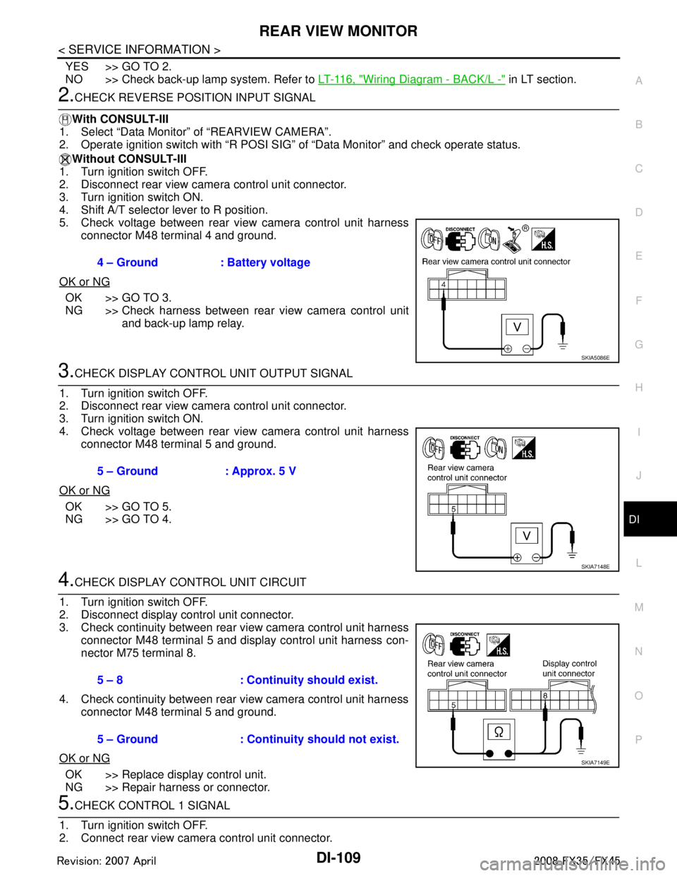
5. Check voltage between rear view camera control unit harness
connector M48 terminal 4 and ground.
OK or NG
OK >> GO TO 3.
NG >> Check harness between rear view camera control unit and back-up lamp relay.
3.CHECK DISPLAY CONTROL UNIT OUTPUT SIGNAL
1. Turn ignition switch OFF.
2. Disconnect rear view camera control unit connector.
3. Turn ignition switch ON.
4. Check voltage between rear view camera control unit harness connector M48 terminal 5 and ground.
OK or NG
OK >> GO TO 5.
NG >> GO TO 4.
4.CHECK DISPLAY CO NTROL UNIT CIRCUIT
1. Turn ignition switch OFF.
2. Disconnect display control unit connector.
3. Check continuity between rear view camera control unit harness connector M48 terminal 5 and display control unit harness con-
nector M75 terminal 8.
4. Check continuity between rear view camera control unit harness connector M48 terminal 5 and ground.
OK or NG
OK >> Replace display control unit.
NG >> Repair harness or connector.
5.CHECK CONTROL 1 SIGNAL
1. Turn ignition switch OFF.
2. Connect rear view camera control unit connector. 4 – Ground : Battery voltage
SKIA5086E
5 – Ground : Approx. 5 V
SKIA7148E
5 – 8 : Continuity should exist.
5 – Ground : Continuity should not exist.
SKIA7149E
3AA93ABC3ACD3AC03ACA3AC03AC63AC53A913A773A893A873A873A8E3A773A983AC73AC93AC03AC3
3A893A873A873A8F3A773A9D3AAF3A8A3A8C3A863A9D3AAF3A8B3A8C