2008 INFINITI FX35 hot
[x] Cancel search: hotPage 2679 of 3924
![INFINITI FX35 2008 Service Manual
FUEL INJECTOR AND FUEL TUBEEM-195
< SERVICE INFORMATION > [VK45DE]
C
D
E
F
G H
I
J
K L
M A
EM
NP
O
2. Start engine. With engine speed increased, check again for fuel leakage at connection points.
CAU INFINITI FX35 2008 Service Manual
FUEL INJECTOR AND FUEL TUBEEM-195
< SERVICE INFORMATION > [VK45DE]
C
D
E
F
G H
I
J
K L
M A
EM
NP
O
2. Start engine. With engine speed increased, check again for fuel leakage at connection points.
CAU](/manual-img/42/57017/w960_57017-2678.png)
FUEL INJECTOR AND FUEL TUBEEM-195
< SERVICE INFORMATION > [VK45DE]
C
D
E
F
G H
I
J
K L
M A
EM
NP
O
2. Start engine. With engine speed increased, check again for fuel leakage at connection points.
CAUTION:
Do not touch engine immediately after st opped, as engine becomes extremely hot.
3AA93ABC3ACD3AC03ACA3AC03AC63AC53A913A773A893A873A873A8E3A773A983AC73AC93AC03AC3
3A893A873A873A8F3A773A9D3AAF3A8A3A8C3A863A9D3AAF3A8B3A8C
Page 2703 of 3924
![INFINITI FX35 2008 Service Manual
CAMSHAFTEM-219
< SERVICE INFORMATION > [VK45DE]
C
D
E
F
G H
I
J
K L
M A
EM
NP
O
b. Use feeler gauge, measure the clearance between valve lifter
and camshaft.
Valve clearance:
Unit: mm (in)
*:Approxi INFINITI FX35 2008 Service Manual
CAMSHAFTEM-219
< SERVICE INFORMATION > [VK45DE]
C
D
E
F
G H
I
J
K L
M A
EM
NP
O
b. Use feeler gauge, measure the clearance between valve lifter
and camshaft.
Valve clearance:
Unit: mm (in)
*:Approxi](/manual-img/42/57017/w960_57017-2702.png)
CAMSHAFTEM-219
< SERVICE INFORMATION > [VK45DE]
C
D
E
F
G H
I
J
K L
M A
EM
NP
O
b. Use feeler gauge, measure the clearance between valve lifter
and camshaft.
Valve clearance:
Unit: mm (in)
*:Approximately 80°C (176 °F)
By referring to the figure, measure the valve clearances at
locations marked “ ×” as shown in the table below (locations
indicated with black arrow in figure).
NOTE:
Firing order 1-8-7-3-6-5-4-2
No. 1 cylinder at compression TDC
c. Rotate crankshaft pulley clockwise (when view from engine front) by 270 degrees from the pos ition of No. 1 cylinder com-
pression TDC to align No. 3 cylinder at TDC of its compression
stroke.
NOTE:
Crankshaft pulley mounting bolt flange has a angle mark every
90 degrees. They can be used as a guide to rotation angle.
SEM139D
Cold Hot * (reference data)
Intake 0.26 - 0.34 (0.010 - 0.013) 0.304 - 0.416 (0.012 - 0.016)
Exhaust 0.29 - 0.37 (0.011 - 0.015) 0.308 - 0.432 (0.012 - 0.017)
Measuring position (right bank) No. 2
CYL. No. 4
CYL. No. 6
CYL. No. 8
CYL.
No. 1 cylinder at com-
pression TDC EXH
×
INT ××
Measuring position (left bank) No. 1
CYL. No. 3
CYL. No. 5
CYL. No. 7
CYL.
No. 1 cylinder at com-
pression TDC INT
××
EXH ××
PBIC2358E
PBIC2346E
3AA93ABC3ACD3AC03ACA3AC03AC63AC53A913A773A893A873A873A8E3A773A983AC73AC93AC03AC3
3A893A873A873A8F3A773A9D3AAF3A8A3A8C3A863A9D3AAF3A8B3A8C
Page 2751 of 3924
![INFINITI FX35 2008 Service Manual
SERVICE DATA AND SPECIFICATIONS (SDS)
EM-267
< SERVICE INFORMATION > [VK45DE]
C
D
E
F
G H
I
J
K L
M A
EM
NP
O
Unit: mm (in)
SPARK PLUG
CAMSHAFT AND CAMSHAFT BEARING
Unit: mm (in)
*: Total indicator r INFINITI FX35 2008 Service Manual
SERVICE DATA AND SPECIFICATIONS (SDS)
EM-267
< SERVICE INFORMATION > [VK45DE]
C
D
E
F
G H
I
J
K L
M A
EM
NP
O
Unit: mm (in)
SPARK PLUG
CAMSHAFT AND CAMSHAFT BEARING
Unit: mm (in)
*: Total indicator r](/manual-img/42/57017/w960_57017-2750.png)
SERVICE DATA AND SPECIFICATIONS (SDS)
EM-267
< SERVICE INFORMATION > [VK45DE]
C
D
E
F
G H
I
J
K L
M A
EM
NP
O
Unit: mm (in)
SPARK PLUG
CAMSHAFT AND CAMSHAFT BEARING
Unit: mm (in)
*: Total indicator reading
Valve Lifter
Unit: mm (in)
Valve Clearance
Unit: mm (in)
Items Limit
Surface distortion Intake manifold (upper) 0.1 (0.004)
Intake manifold (lower) 0.1 (0.004)
Exhaust manifold 0.3 (0.012)
Make
NGK
Standard type PLFR5A-11
Hot type PLFR4A-11
Cold type PLFR6A-11
Gap (Nominal) 1.1 mm (0.043 in)
Items Standard Limit
Camshaft journal clearance No. 1 0.045 - 0.083 (0.0018 - 0.0033) —
No. 2, 3, 4, 5 0.030 - 0.068 (0.0012 - 0.0027) —
Camshaft journal diameter No. 1 25.938 - 25.955 (1.0212 - 1.0218) —
No. 2, 3, 4, 5 25.953 - 25.970 (1.0218 - 1.0224) —
Camshaft bracket inner diameter 26.000 - 26.021 (1.0236 - 1.0244) —
Camshaft end play 0.115 - 0.188 (0.0045 - 0.0074) —
Cam height “A” Intake 44.865 - 45.055 (1.7663 - 1.7738) 0.2 (0.008)
Exhaust 43.925 - 44.115 (1.7293 - 1.7368) 0.2 (0.008)
Camshaft runout (TIR*) — 0.02 (0.001)
Camshaft sprocket runout (TIR*) — 0.15 (0.059)
SEM671
Items Standard
Valve lifter outer diameter 33.977 - 33.987 (1.3377 - 1.3381)
Valve lifter hole diameter 34.000 - 34.016 (1.3386 - 1.3392)
Valve lifter clearance 0.013 - 0.039 (0.0005 - 0.0015)
Items Cold Hot* (reference data)
3AA93ABC3ACD3AC03ACA3AC03AC63AC53A913A773A893A873A873A8E3A773A983AC73AC93AC03AC3
3A893A873A873A8F3A773A9D3AAF3A8A3A8C3A863A9D3AAF3A8B3A8C
Page 2763 of 3924
EXHAUST SYSTEMEX-3
< SERVICE INFORMATION >
C
DE
F
G H
I
J
K L
M A
EX
NP
O
EXHAUST SYSTEM
Checking Exhaust SystemINFOID:0000000001327114
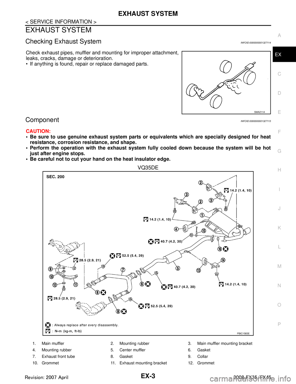
Check exhaust pipes, muffler and mounting for improper attachment,
leaks, cracks, damage or deterioration.
• If anything is found, repair or replace damaged parts.
ComponentINFOID:0000000001327115
CAUTION:
• Be sure to use genuine exhaust system parts or
equivalents which are specially designed for heat
resistance, corrosion resistance, and shape.
Perform the operation with the exhaust system full y cooled down because the system will be hot
just after engine stops.
Be careful not to cut your hand on the heat insulator edge.
VQ35DE
SMA211A
PBIC1583E
1. Main muffler 2. Mounting rubber 3. Main muffler mounting bracket
4. Mounting rubber 5. Center muffler 6. Gasket
7. Exhaust front tube 8. Gasket 9. Collar
10. Grommet 11. Exhaust mounting bracket 12. Grommet
3AA93ABC3ACD3AC03ACA3AC03AC63AC53A913A773A893A873A873A8E3A773A983AC73AC93AC03AC3
3A893A873A873A8F3A773A9D3AAF3A8A3A8C3A863A9D3AAF3A8B3A8C
Page 2866 of 3924
GI-4
< SERVICE INFORMATION >
PRECAUTIONS
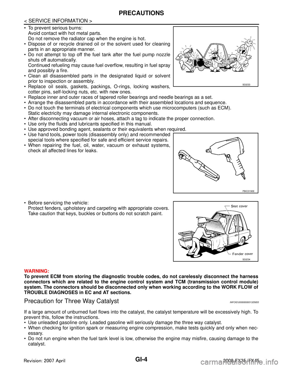
To prevent serious burns:Avoid contact with hot metal parts.
Do not remove the radiator cap when the engine is hot.
Dispose of or recycle drained oil or the solvent used for cleaning parts in an appropriate manner.
Do not attempt to top off the fuel tank after the fuel pump nozzle
shuts off automatically.
Continued refueling may cause fuel overflow, resulting in fuel spray
and possibly a fire.
Clean all disassembled parts in the designated liquid or solvent prior to inspection or assembly.
Replace oil seals, gaskets, packings, O-rings, locking washers, cotter pins, self-locking nuts, etc. with new ones.
Replace inner and outer races of tapered roller bearings and needle bearings as a set.
Arrange the disassembled parts in accordance with their assembled locations and sequence.
Do not touch the terminals of electrical com ponents which use microcomputers (such as ECM).
Static electricity may damage internal electronic components.
After disconnecting vacuum or air hoses, atta ch a tag to indicate the proper connection.
Use only the fluids and lubricants specified in this manual.
Use approved bonding agent, sealants or their equivalents when required.
Use hand tools, power tools (disassembly only) and recommended special tools where specified for safe and efficient service repairs.
When repairing the fuel, oil, water, vacuum or exhaust systems,
check all affected lines for leaks.
Before servicing the vehicle: Protect fenders, upholstery and carpeting with appropriate covers.
Take caution that keys, buckles or buttons do not scratch paint.
WARNING:
To prevent ECM from storing the diagnostic tro uble codes, do not carelessly disconnect the harness
connectors which are related to the engine cont rol system and TCM (transmission control module)
system. The connectors should be disconnected on ly when working according to the WORK FLOW of
TROUBLE DIAGNOSES in EC and AT sections.
Precaution for Three Way CatalystINFOID:0000000001325655
If a large amount of unburned fuel flows into the catalyst , the catalyst temperature will be excessively high. To
prevent this, follow the instructions.
Use unleaded gasoline only. Leaded gasoline will seriously damage the three way catalyst.
When checking for ignition spark or measuring engine compression, make tests quickly and only when nec- essary.
Do not run engine when the fuel tank level is low, otherwise the engine may misfire, causing damage to the
catalyst.
SGI233
PBIC0190E
SGI234
3AA93ABC3ACD3AC03ACA3AC03AC63AC53A913A773A893A873A873A8E3A773A983AC73AC93AC03AC3
3A893A873A873A8F3A773A9D3AAF3A8A3A8C3A863A9D3AAF3A8B3A8C
Page 2888 of 3924
GI-26
< SERVICE INFORMATION >
SERVICE INFORMATION FOR ELECTRICAL INCIDENT
Cold or hot start up
Get a thorough description of the incident from the customer. It is important for simulating the conditions of the
problem.
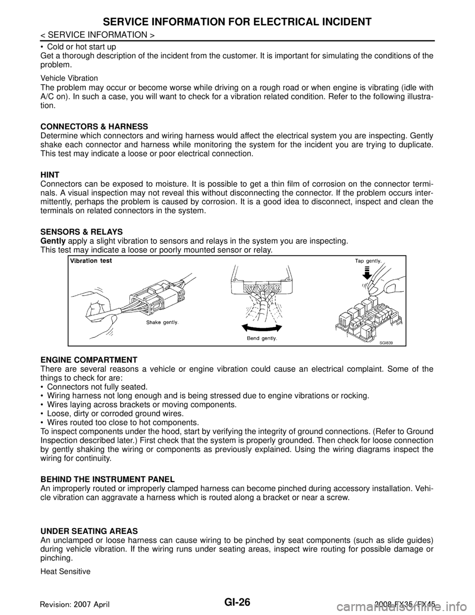
Vehicle Vibration
The problem may occur or become worse while drivi ng on a rough road or when engine is vibrating (idle with
A/C on). In such a case, you will want to check for a vi bration related condition. Refer to the following illustra-
tion.
CONNECTORS & HARNESS
Determine which connectors and wiring harness would affect the electrical system you are inspecting. Gently
shake each connector and harness while monitoring the sy stem for the incident you are trying to duplicate.
This test may indicate a loose or poor electrical connection.
HINT
Connectors can be exposed to moisture. It is possible to get a thin film of corrosion on the connector termi-
nals. A visual inspection may not reveal this without disconnecting the connector. If the problem occurs inter-
mittently, perhaps the problem is caused by corrosion. It is a good idea to disconnect, inspect and clean the
terminals on related connectors in the system.
SENSORS & RELAYS
Gently apply a slight vibration to sensors and relays in the system you are inspecting.
This test may indicate a loose or poorly mounted sensor or relay.
ENGINE COMPARTMENT
There are several reasons a vehicle or engine vibration could cause an e\
lectrical complaint. Some of the
things to check for are:
Connectors not fully seated.
Wiring harness not long enough and is being stressed due to engine vibrations or rocking.
Wires laying across brackets or moving components.
Loose, dirty or corroded ground wires.
Wires routed too close to hot components.
To inspect components under the hood, start by verifyi ng the integrity of ground connections. (Refer to Ground
Inspection described later.) First check that the system is properly grounded. Then check for loose connection
by gently shaking the wiring or components as previous ly explained. Using the wiring diagrams inspect the
wiring for continuity.
BEHIND THE INSTRUMENT PANEL
An improperly routed or improperly clamped harness can become pinched during accessory installation. Vehi-
cle vibration can aggravate a harness which is routed along a bracket or near a screw.
UNDER SEATING AREAS
An unclamped or loose harness can cause wiring to be pinched by seat components (such as slide guides)
during vehicle vibration. If the wiring runs under s eating areas, inspect wire routing for possible damage or
pinching.
Heat Sensitive
SGI839
3AA93ABC3ACD3AC03ACA3AC03AC63AC53A913A773A893A873A873A8E3A773A983AC73AC93AC03AC3
3A893A873A873A8F3A773A9D3AAF3A8A3A8C3A863A9D3AAF3A8B3A8C
Page 2889 of 3924
SERVICE INFORMATION FOR ELECTRICAL INCIDENTGI-27
< SERVICE INFORMATION >
C
DE
F
G H
I
J
K L
M B
GI
N
O P
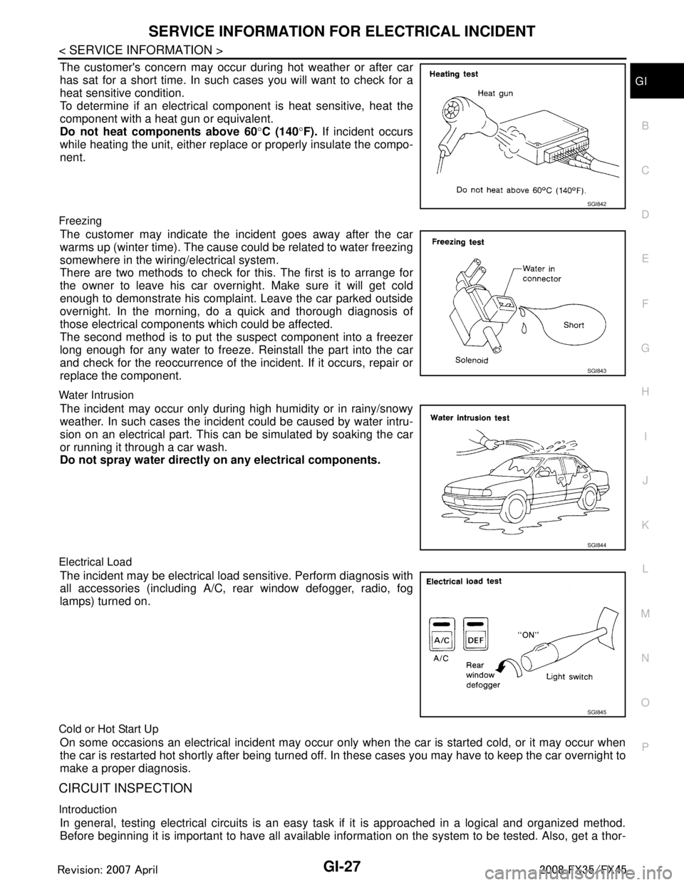
The customer's concern may occur during hot weather or after car
has sat for a short time. In such cases you will want to check for a
heat sensitive condition.
To determine if an electrical com ponent is heat sensitive, heat the
component with a heat gun or equivalent.
Do not heat components above 60 °C (140 °F). If incident occurs
while heating the unit, either replac e or properly insulate the compo-
nent.
Freezing
The customer may indicate the incident goes away after the car
warms up (winter time). The cause could be related to water freezing
somewhere in the wiring/electrical system.
There are two methods to check for this. The first is to arrange for
the owner to leave his car overnight. Make sure it will get cold
enough to demonstrate his complaint. Leave the car parked outside
overnight. In the morning, do a quick and thorough diagnosis of
those electrical components which could be affected.
The second method is to put the suspect component into a freezer
long enough for any water to freeze. Reinstall the part into the car
and check for the reoccurrence of the incident. If it occurs, repair or
replace the component.
Water Intrusion
The incident may occur only during high humidity or in rainy/snowy
weather. In such cases the incident could be caused by water intru-
sion on an electrical part. This c an be simulated by soaking the car
or running it through a car wash.
Do not spray water directly on any electrical components.
Electrical Load
The incident may be electrical load sensitive. Perform diagnosis with
all accessories (including A/C, rear window defogger, radio, fog
lamps) turned on.
Cold or Hot Start Up
On some occasions an electrical incident may occur only when the car is started cold, or it may occur when
the car is restarted hot shortly after being turned off. In these cases you may have to keep the car overnight to
make a proper diagnosis.
CIRCUIT INSPECTION
Introduction
In general, testing electrical circuits is an easy ta sk if it is approached in a logical and organized method.
Before beginning it is important to have all available in formation on the system to be tested. Also, get a thor-
SGI842
SGI843
SGI844
SGI845
3AA93ABC3ACD3AC03ACA3AC03AC63AC53A913A773A893A873A873A8E3A773A983AC73AC93AC03AC3
3A893A873A873A8F3A773A9D3AAF3A8A3A8C3A863A9D3AAF3A8B3A8C
Page 2991 of 3924
GW-78
< SERVICE INFORMATION >
REAR WINDOW DEFOGGER
Conductive silver composition (Dupont No. 4817 or equivalent)
Ruler 30 cm (11.8 in) long
Drawing pen
Heat gun
Alcohol
Cloth
REPAIRING PROCEDURE
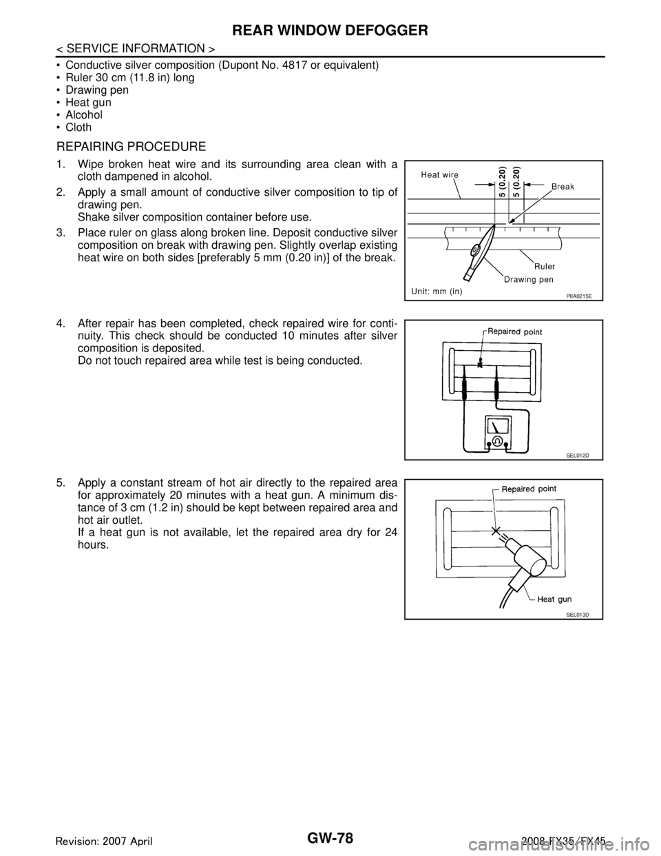
1. Wipe broken heat wire and its surrounding area clean with acloth dampened in alcohol.
2. Apply a small amount of conductive silver composition to tip of
drawing pen.
Shake silver composition container before use.
3. Place ruler on glass along broken line. Deposit conductive silver composition on break with drawing pen. Slightly overlap existing
heat wire on both sides [preferably 5 mm (0.20 in)] of the break.
4. After repair has been completed, check repaired wire for conti- nuity. This check should be conducted 10 minutes after silver
composition is deposited.
Do not touch repaired area while test is being conducted.
5. Apply a constant stream of hot air directly to the repaired area for approximately 20 minutes with a heat gun. A minimum dis-
tance of 3 cm (1.2 in) should be kept between repaired area and
hot air outlet.
If a heat gun is not available, let the repaired area dry for 24
hours.
PIIA0215E
SEL012D
SEL013D
3AA93ABC3ACD3AC03ACA3AC03AC63AC53A913A773A893A873A873A8E3A773A983AC73AC93AC03AC3
3A893A873A873A8F3A773A9D3AAF3A8A3A8C3A863A9D3AAF3A8B3A8C