2008 INFINITI FX35 selection pg
[x] Cancel search: selection pgPage 2739 of 3924
![INFINITI FX35 2008 Service Manual
CYLINDER BLOCKEM-255
< SERVICE INFORMATION > [VK45DE]
C
D
E
F
G H
I
J
K L
M A
EM
NP
O
Main Bearing Selection Table (No. 2, 3 and 4 Journal)
Main Bearing Grade Table (All Journals)
Unit: mm (in)
PBIC2 INFINITI FX35 2008 Service Manual
CYLINDER BLOCKEM-255
< SERVICE INFORMATION > [VK45DE]
C
D
E
F
G H
I
J
K L
M A
EM
NP
O
Main Bearing Selection Table (No. 2, 3 and 4 Journal)
Main Bearing Grade Table (All Journals)
Unit: mm (in)
PBIC2](/manual-img/42/57017/w960_57017-2738.png)
CYLINDER BLOCKEM-255
< SERVICE INFORMATION > [VK45DE]
C
D
E
F
G H
I
J
K L
M A
EM
NP
O
Main Bearing Selection Table (No. 2, 3 and 4 Journal)
Main Bearing Grade Table (All Journals)
Unit: mm (in)
PBIC2376E
Grade number Thickness Identification color Remarks
0 2.483 - 2.486 (0.0978 - 0.0979) Black
Grade and color are the same
for upper and lower bearings.
1 2.486 - 2.489 (0.0979 - 0.0980) Brown
2 2.489 - 2.492 (0.0980 - 0.0981) Green
3 2.492 - 2.495 (0.0981 - 0.0982) Yellow
4 2.495 - 2.498 (0.0982 - 0.0983) Blue
5 2.498 - 2.501 (0.0983 - 0.0985) Pink
6 2.501 - 2.504 (0.0985 - 0.0986) Purple
7 2.504 - 2.507 (0.0986 - 0.0987) White
8 2.507 - 2.510 (0.0987 - 0.0988) Red
3AA93ABC3ACD3AC03ACA3AC03AC63AC53A913A773A893A873A873A8E3A773A983AC73AC93AC03AC3
3A893A873A873A8F3A773A9D3AAF3A8A3A8C3A863A9D3AAF3A8B3A8C
Page 2819 of 3924
FFD-28
< SERVICE INFORMATION >
FRONT FINAL DRIVE ASSEMBLY
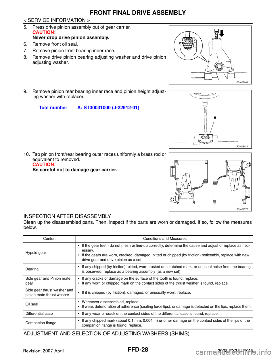
5. Press drive pinion assembly out of gear carrier.CAUTION:
Never drop drive pinion assembly.
6. Remove front oil seal.
7. Remove pinion front bearing inner race.
8. Remove drive pinion bearing adjusting washer and drive pinion adjusting washer.
9. Remove pinion rear bearing inner race and pinion height adjust- ing washer with replacer.
10. Tap pinion front/rear bearing outer races uniformly a brass rod or equivalent to removed.
CAUTION:
Be careful not to damage gear carrier.
INSPECTION AFTER DISASSEMBLY
Clean up the disassembled parts. Then, inspect if the parts are worn or damaged. If so, follow the measures
below.
ADJUSTMENT AND SELECTION OF ADJUSTING WASHERS (SHIMS)
PDIA0800J
Tool number A: ST30031000 (J-22912-01)
PDIA0801J
PDIA0677E
Content Conditions and Measures
Hypoid gear If the gear teeth do not mesh or line-up correctly, determine the cause and adjust or replace as nec-
essary.
If the gears are worn, cracked, damaged, pitted or chipped (by friction) noticeably, replace with new drive gear and drive pinion as a set.
Bearing If any chipped (by friction), pitted, worn, rusted or scratched mark, or unusual noise from the bearing
is observed, replace as a bearing assembly (as a new set).
Side gear and Pinion mate
gear If any cracks or damage on the surface of the tooth is found, replace.
If any worn or chipped mark on the contact sides of the thrust washer is found, replace.
Side gear thrust washer and
pinion mate thrust washer If it is chipped (by friction), damaged, or unusually worn, replace.
Oil seal Whenever disassembled, replace.
If wear, deterioration of adherence (sealing force lips), or damage is detected on the lips, replace them.
Differential case If any wear or crack on the contact sides of the differential case is found, replace.
Companion flange If any chipped mark (about 0.1 mm, 0.004 in) or other damage on the contact sides of the lips of the
companion flange is found, replace.
3AA93ABC3ACD3AC03ACA3AC03AC63AC53A913A773A893A873A873A8E3A773A983AC73AC93AC03AC3
3A893A873A873A8F3A773A9D3AAF3A8A3A8C3A863A9D3AAF3A8B3A8C
Page 2822 of 3924
FRONT FINAL DRIVE ASSEMBLYFFD-31
< SERVICE INFORMATION >
CEF
G H
I
J
K L
M A
B
FFD
N
O P
9. If the turning torque is outside the specification, use a thicker/ thinner side bearing adjusting shim to adjust. Refer to FFD-39,
"Inspection and Adjustment".
10. Record the total amount of shim thickness required for the cor- rect carrier side bearing preload.
Pinion Gear Height
If the hypoid gear set has been replaced, se lect the pinion height adjusting washer.
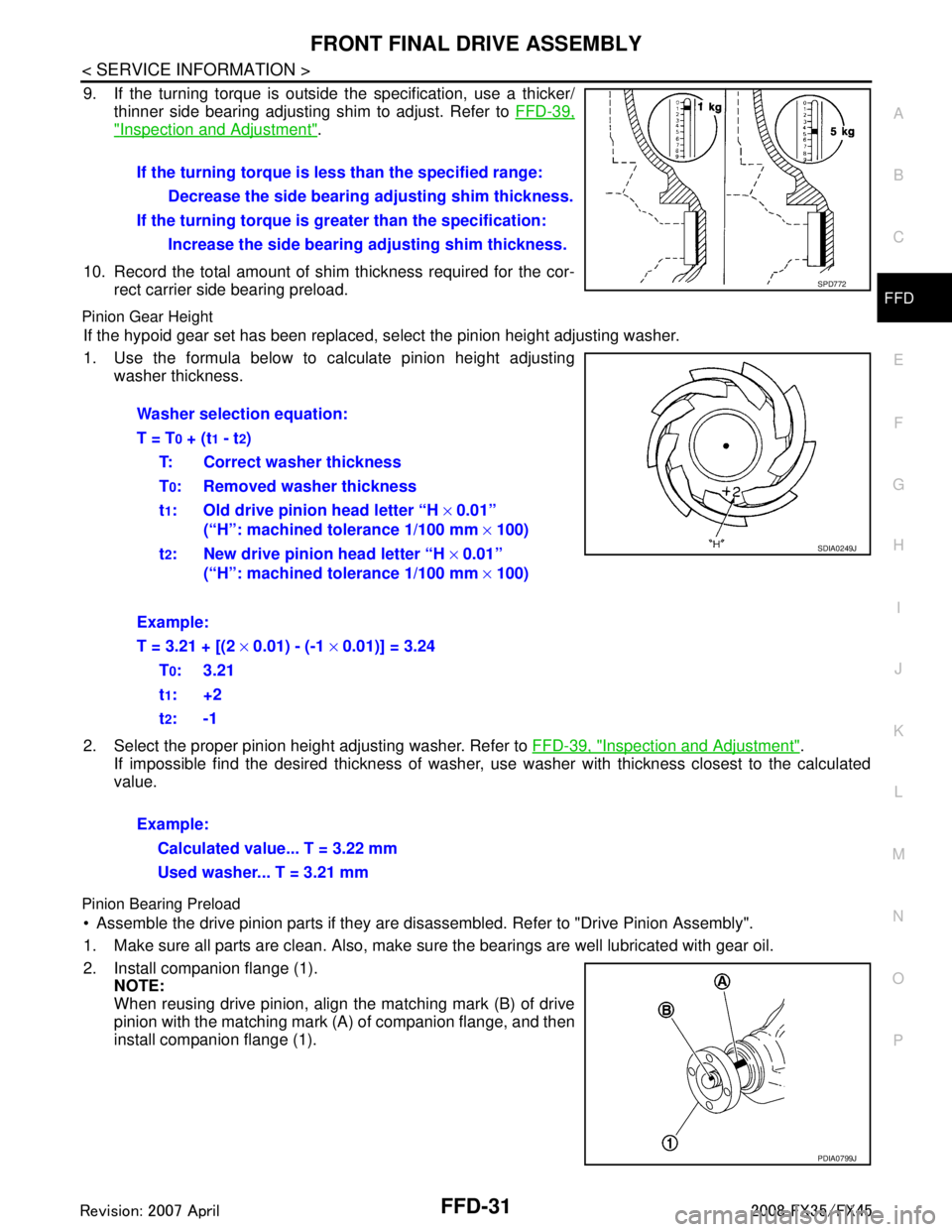
1. Use the formula below to calculate pinion height adjusting washer thickness.
2. Select the proper pinion height adjusting washer. Refer to FFD-39, "
Inspection and Adjustment".
If impossible find the desired thickness of washer, us e washer with thickness closest to the calculated
value.
Pinion Bearing Preload
Assemble the drive pinion parts if they are disassembled. Refer to "Drive Pinion Assembly".
1. Make sure all parts are clean. Also, make sure the bearings are well lubricated with gear oil.
2. Install companion flange (1). NOTE:
When reusing drive pinion, align the matching mark (B) of drive
pinion with the matching mark (A) of companion flange, and then
install companion flange (1).If the turning torque is l
ess than the specified range:
Decrease the side bearing adjusting shim thickness.
If the turning torque is gr eater than the specification:
Increase the side bearing adjusting shim thickness.
SPD772
Washer selection equation:
T = T
0 + (t1 - t2)
T: Correct washer thickness
T
0: Removed washer thickness
t
1: Old drive pinion head letter “H × 0.01”
(“H”: machined tolerance 1/100 mm × 100)
t
2: New drive pinion head letter “H × 0.01”
(“H”: machined tolerance 1/100 mm × 100)
Example:
T = 3.21 + [(2 × 0.01) - (-1 × 0.01)] = 3.24
T
0:3.21
t
1:+2
t
2:-1
Example: Calculated value... T = 3.22 mm
Used washer... T = 3.21 mm
SDIA0249J
PDIA0799J
3AA93ABC3ACD3AC03ACA3AC03AC63AC53A913A773A893A873A873A8E3A773A983AC73AC93AC03AC3
3A893A873A873A8F3A773A9D3AAF3A8A3A8C3A863A9D3AAF3A8B3A8C
Page 3119 of 3924
HEADLAMP - XENON TYPE -LT-17
< SERVICE INFORMATION >
C
DE
F
G H
I
J
L
M A
B
LT
N
O P
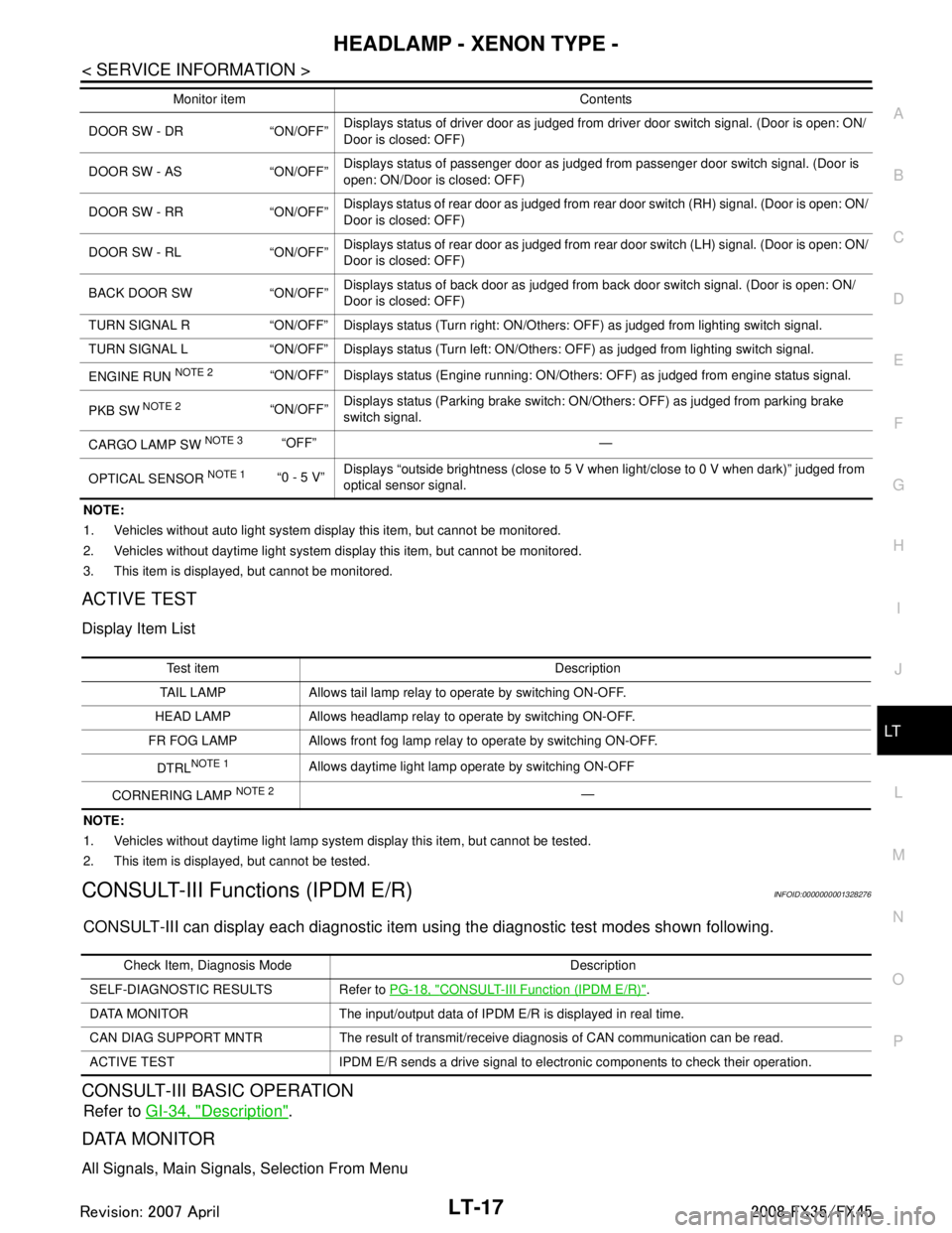
NOTE:
1. Vehicles without auto light system display this item, but cannot be monitored.
2. Vehicles without daytime light system display this item, but cannot be monitored.
3. This item is displayed, but cannot be monitored.
ACTIVE TEST
Display Item List
NOTE:
1. Vehicles without daytime light lamp system display this item, but cannot be tested.
2. This item is displayed, but cannot be tested.
CONSULT-III Functions (IPDM E/R)INFOID:0000000001328276
CONSULT-III can display each diagnostic item us ing the diagnostic test modes shown following.
CONSULT-III BASIC OPERATION
Refer to GI-34, "Description".
DATA MONITOR
All Signals, Main Signals, Selection From Menu
DOOR SW - DR “ON/OFF” Displays status of driver door as judged from driver door switch signal. (Door is open: ON/
Door is closed: OFF)
DOOR SW - AS “ON/OFF” Displays status of passenger door as judged from passenger door switch signal. (Door is
open: ON/Door is closed: OFF)
DOOR SW - RR “ON/OFF” Displays status of rear door as judged from rear door switch (RH) signal. (Door is open: ON/
Door is closed: OFF)
DOOR SW - RL “ON/OFF” Displays status of rear door as judged from rear door switch (LH) signal. (Door is open: ON/
Door is closed: OFF)
BACK DOOR SW “ON/OFF” Displays status of back door as judged from back door switch signal. (Door is open: ON/
Door is closed: OFF)
TURN SIGNAL R “ON/OFF” Display s status (Turn right: ON/Others: OFF) as judged from lighting switch signal.
TURN SIGNAL L “ON/OFF” Display s status (Turn left: ON/Others: OFF) as judged from lighting switch signal.
ENGINE RUN
NOTE 2“ON/OFF” Displays status (Engine running: ON/Others: OFF) as judged from engine status signal.
PKB SW
NOTE 2“ON/OFF” Displays status (Parking brake switch: ON/Others: OFF) as judged from parking brake
switch signal.
CARGO LAMP SW
NOTE 3 “OFF” —
OPTICAL SENSOR
NOTE 1 “0 - 5 V” Displays “outside brightness (close to 5 V when light/close to 0 V when dark)” judged from
optical sensor signal.
Monitor item Contents
Te s t i t e m D e s c r i p t i o n
TAIL LAMP Allows tail lamp relay to operate by switching ON-OFF.
HEAD LAMP Allows headlamp relay to operate by switching ON-OFF.
FR FOG LAMP Allows front fog lamp relay to operate by switching ON-OFF.
DTRL
NOTE 1Allows daytime light lamp operate by switching ON-OFF
CORNERING LAMP
NOTE 2—
Check Item, Diagnosis Mode Description
SELF-DIAGNOSTIC RESULTS Refer to PG-18, "
CONSULT-III Function (IPDM E/R)".
DATA MONITOR The input/output data of IPDM E/R is displayed in real time.
CAN DIAG SUPPORT MNTR The result of transmit/receive diagnosis of CAN communication can be read.
ACTIVE TEST IPDM E/R sends a drive signal to electronic components to check their operation.
3AA93ABC3ACD3AC03ACA3AC03AC63AC53A913A773A893A873A873A8E3A773A983AC73AC93AC03AC3
3A893A873A873A8F3A773A9D3AAF3A8A3A8C3A863A9D3AAF3A8B3A8C
Page 3120 of 3924
LT-18
< SERVICE INFORMATION >
HEADLAMP - XENON TYPE -
NOTE:
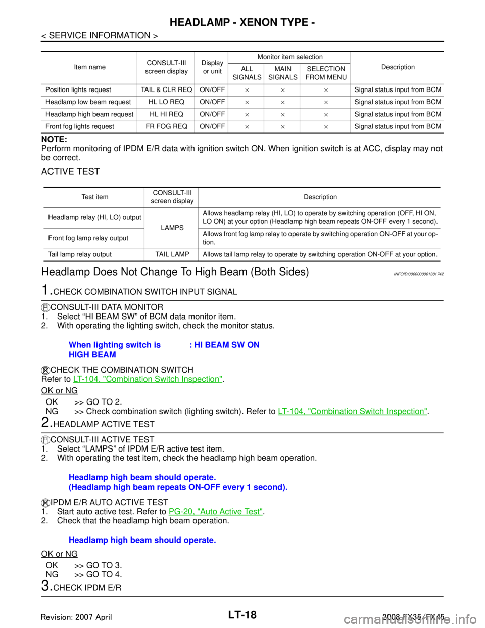
Perform monitoring of IPDM E/R data with ignition switch ON. When ignition switch is at ACC, display may not
be correct.
ACTIVE TEST
Headlamp Does Not Change To High Beam (Both Sides)INFOID:0000000001381742
1.CHECK COMBINATION SWITCH INPUT SIGNAL
CONSULT-III DATA MONITOR
1. Select “HI BEAM SW” of BCM data monitor item.
2. With operating the lighting switch, check the monitor status.
CHECK THE COMBINATION SWITCH
Refer to LT-104, "
Combination Switch Inspection".
OK or NG
OK >> GO TO 2.
NG >> Check combination switch (lighting switch). Refer to LT-104, "
Combination Switch Inspection".
2.HEADLAMP ACTIVE TEST
CONSULT-III ACTIVE TEST
1. Select “LAMPS” of IPDM E/R active test item.
2. With operating the test item, check the headlamp high beam operation.
IPDM E/R AUTO ACTIVE TEST
1. Start auto active test. Refer to PG-20, "
Auto Active Test".
2. Check that the headlamp high beam operation.
OK or NG
OK >> GO TO 3.
NG >> GO TO 4.
3.CHECK IPDM E/R
Item name CONSULT-III
screen display Display
or unit Monitor item selection
Description
ALL
SIGNALS MAIN
SIGNALS SELECTION
FROM MENU
Position lights request TAIL & CLR REQ ON/OFF ×× ×Signal status input from BCM
Headlamp low beam request HL LO REQ ON/OFF ×× ×Signal status input from BCM
Headlamp high beam request HL HI REQ ON/OFF ×× ×Signal status input from BCM
Front fog lights request FR FOG REQ ON/OFF ×× ×Signal status input from BCM
Te s t i t e mCONSULT-III
screen display Description
Headlamp relay (HI, LO) output
LAMPSAllows headlamp relay (HI, LO) to operate by switching operation (OFF, HI ON,
LO ON) at your option (Headlamp high beam repeats ON-OFF every 1 second).
Front fog lamp relay output Allows front fog lamp relay to operate by switching operation ON-OFF at your op-
tion.
Tail lamp relay output TAIL LAMP Allows tail lamp relay to operate by switching operation ON-OFF at your option.
When lighting switch is
HIGH BEAM : HI BEAM SW ON
Headlamp high beam should operate.
(Headlamp high beam repeats ON-OFF every 1 second).
Headlamp high beam should operate.
3AA93ABC3ACD3AC03ACA3AC03AC63AC53A913A773A893A873A873A8E3A773A983AC73AC93AC03AC3
3A893A873A873A8F3A773A9D3AAF3A8A3A8C3A863A9D3AAF3A8B3A8C
Page 3160 of 3924
LT-58
< SERVICE INFORMATION >
AUTO LIGHT SYSTEM
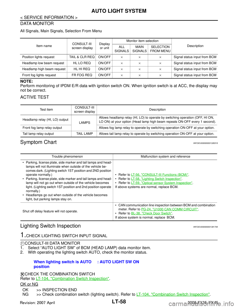
DATA MONITOR
All Signals, Main Signals, Selection From Menu
NOTE:
Perform monitoring of IPDM E/R data with ignition switch ON. When ignition switch is at ACC, the display may
not be correct.
ACTIVE TEST
Symptom ChartINFOID:0000000001328319
Lighting Switch InspectionINFOID:0000000001381749
1.CHECK LIGHTING SWITCH INPUT SIGNAL
CONSULT-III DATA MONITOR
1. Select “AUTO LIGHT SW” of BCM (HEAD LAMP) data monitor item.
2. With operating the lighting switch AUTO, check the monitor status.
CHECK THE COMBINATION SWITCH
Refer to LT-104, "
Combination Switch Inspection".
OK or NG
OK >> INSPECTION END
NG >> Check combination switch (lighting switch). Refer to LT-104, "
Combination Switch Inspection".
Item nameCONSULT-III
screen display Display
or unit Monitor item selection
Description
ALL
SIGNALS MAIN
SIGNALS SELECTION
FROM MENU
Position lights reques t TAIL & CLR REQ ON/OFF ×× ×Signal status input from BCM
Headlamp low beam request HL LO REQ ON/OFF ×× ×Signal status input from BCM
Headlamp high beam request HL HI REQ ON/OFF ×× ×Signal status input from BCM
Front fog lights request FR FOG REQ ON/OFF ×× ×Signal status input from BCM
Te s t i t e mCONSULT-III
screen display Description
Headlamp relay (HI, LO) output LAMPSAllows headlamp relay (HI, LO) to operate by switching operation (OFF, HI ON,
LO ON) at your option (Head lamp high beam repeats ON-OFF every 1 second).
Front fog lamp relay output Allows fog lamp relay to operate by switching operation ON-OFF at your option.
Tail lamp relay output TAIL LAMP Allows tail lamp relay to operate by switching operation ON-OFF at your option.
Trouble phenomenon Malfunction system and reference
Parking, license plate, side marker and tail lamps and head- lamps will not illuminate when outside of the vehicle be-
comes dark. (Lighting switch 1ST position and 2ND position
operate normally.)
Parking, license plate, side marker and tail lamps and head-
lamp will not go out when outside of the vehicle becomes
light. (Lighting switch 1ST position and 2nd position operate
normally.)
Headlamps go out when outside of the vehicle becomes light, but parking lamps stay on. Refer to
LT- 5 6 , "
CONSULT-III Functions (BCM)".
Refer to LT- 5 8 , "
Lighting Switch Inspection".
Refer to LT- 5 9 , "
Optical sensor System Inspection".
If above systems are normal, replace BCM.
Shut off delay feature will not operate. CAN communication line inspection between BCM and combination
meter. Refer to PG-24, "
U1000 CAN COMM CIRCUIT".
Refer to BL-38, "
Check Door Switch".
If above system is normal, replace BCM.
When lighting switch is AUTO
position : AUTO LIGHT SW ON
3AA93ABC3ACD3AC03ACA3AC03AC63AC53A913A773A893A873A873A8E3A773A983AC73AC93AC03AC3
3A893A873A873A8F3A773A9D3AAF3A8A3A8C3A863A9D3AAF3A8B3A8C
Page 3568 of 3924
RFD-26
< SERVICE INFORMATION >
REAR FINAL DRIVE ASSEMBLY
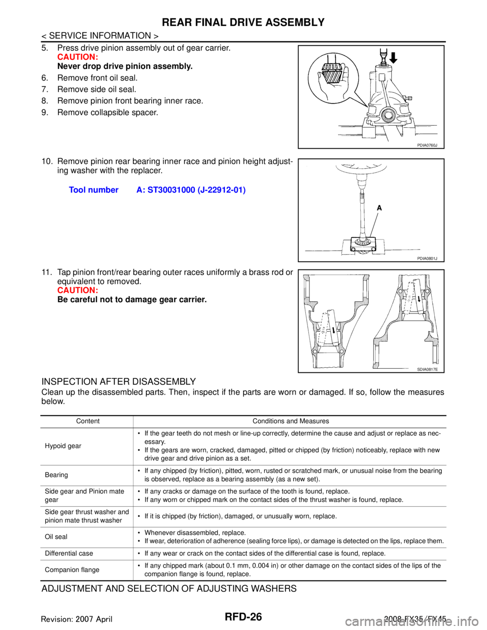
5. Press drive pinion assembly out of gear carrier.CAUTION:
Never drop drive pinion assembly.
6. Remove front oil seal.
7. Remove side oil seal.
8. Remove pinion front bearing inner race.
9. Remove collapsible spacer.
10. Remove pinion rear bearing inner race and pinion height adjust- ing washer with the replacer.
11. Tap pinion front/rear bearing outer races uniformly a brass rod or equivalent to removed.
CAUTION:
Be careful not to damage gear carrier.
INSPECTION AFTER DISASSEMBLY
Clean up the disassembled parts. Then, inspect if the parts are worn or damaged. If so, follow the measures
below.
ADJUSTMENT AND SELECTION OF ADJUSTING WASHERS
PDIA0760J
Tool number A: ST30031000 (J-22912-01)
PDIA0801J
SDIA0817E
Content Conditions and Measures
Hypoid gear If the gear teeth do not mesh or line-up correctly, determine the cause and adjust or replace as nec-
essary.
If the gears are worn, cracked, damaged, pitted or chipped (by friction) noticeably, replace with new drive gear and drive pinion as a set.
Bearing If any chipped (by friction), pitted, worn, rusted or scratched mark, or unusual noise from the bearing
is observed, replace as a bearing assembly (as a new set).
Side gear and Pinion mate
gear If any cracks or damage on the surface of the tooth is found, replace.
If any worn or chipped mark on the contact sides of the thrust washer is found, replace.
Side gear thrust washer and
pinion mate thrust washer If it is chipped (by friction), damaged, or unusually worn, replace.
Oil seal Whenever disassembled, replace.
If wear, deterioration of adherence (sealing force lips), or damage is detected on the lips, replace them.
Differential case If any wear or crack on the contact sides of the differential case is found, replace.
Companion flange If any chipped mark (about 0.1 mm, 0.004 in) or other damage on the contact sides of the lips of the
companion flange is found, replace.
3AA93ABC3ACD3AC03ACA3AC03AC63AC53A913A773A893A873A873A8E3A773A983AC73AC93AC03AC3
3A893A873A873A8F3A773A9D3AAF3A8A3A8C3A863A9D3AAF3A8B3A8C
Page 3679 of 3924
SE-40
< SERVICE INFORMATION >
AUTOMATIC DRIVE POSITIONER
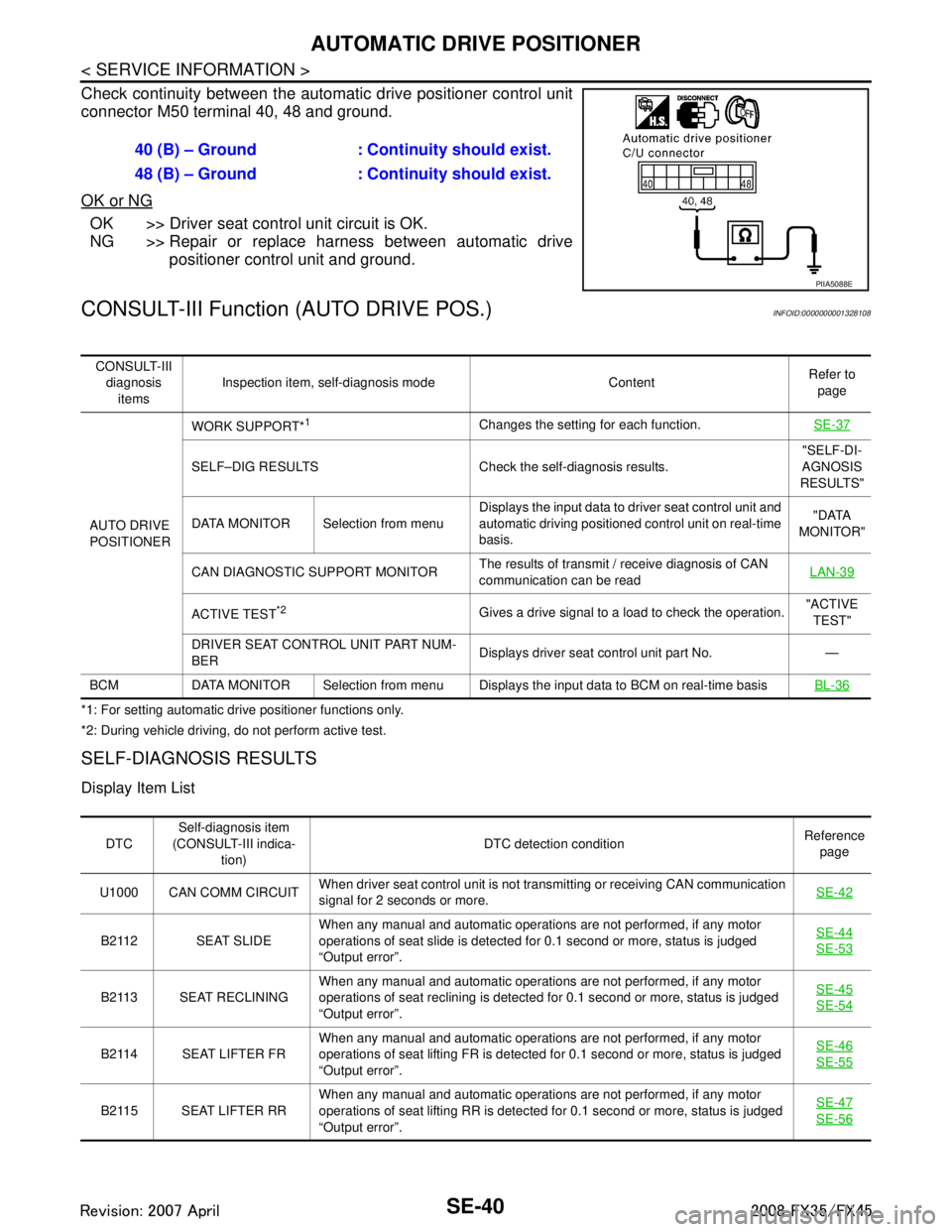
Check continuity between the automatic drive positioner control unit
connector M50 terminal 40, 48 and ground.
OK or NG
OK >> Driver seat control unit circuit is OK.
NG >> Repair or replace harness between automatic drive
positioner control unit and ground.
CONSULT-III Function (AUTO DRIVE POS.)INFOID:0000000001328108
*1: For setting automatic drive positioner functions only.
*2: During vehicle driving, do not perform active test.
SELF-DIAGNOSIS RESULTS
Display Item List
40 (B) – Ground : Continuity should exist.
48 (B) – Ground : Continuity should exist.
PIIA5088E
CONSULT-III
diagnosis items Inspection item, self-diagnosis mode Content
Refer to
page
AUTO DRIVE
POSITIONER WORK SUPPORT*
1Changes the setting for each function.
SE-37
SELF–DIG RESULTS Check the self-diagnosis results. "SELF-DI-
AGNOSIS
RESULTS"
DATA MONITOR Selection from menu Displays the input data to driver seat control unit and
automatic driving positioned control unit on real-time
basis. "DATA
MONITOR"
CAN DIAGNOSTIC SUPPORT MONITOR The results of transmit / receive diagnosis of CAN
communication can be read LAN-39
ACTIVE TEST*2Gives a drive signal to a load to check the operation.
"ACTIVE
TEST"
DRIVER SEAT CONTROL UNIT PART NUM-
BER Displays driver seat control unit part No. —
BCM DATA MONITOR Selection from menu Displays the input data to BCM on real-time basisBL-36
DTCSelf-diagnosis item
(CONSULT-III indica- tion) DTC detection condition
Reference
page
U1000 CAN COMM CIRCUIT When driver seat control unit is not transmitting or receiving CAN communication
signal for 2 seconds or more.
SE-42
B2112 SEAT SLIDEWhen any manual and automatic operations are not performed, if any motor
operations of seat slide is detected for 0.1 second or more, status is judged
“Output error”. SE-44SE-53
B2113 SEAT RECLINING
When any manual and automatic operations are not performed, if any motor
operations of seat reclining is detected for 0.1 second or more, status is judged
“Output error”. SE-45SE-54
B2114 SEAT LIFTER FR
When any manual and automatic operations are not performed, if any motor
operations of seat lifting FR is detected for 0.1 second or more, status is judged
“Output error”. SE-46SE-55
B2115 SEAT LIFTER RR
When any manual and automatic operations are not performed, if any motor
operations of seat lifting RR is detected for 0.1 second or more, status is judged
“Output error”. SE-47SE-56
3AA93ABC3ACD3AC03ACA3AC03AC63AC53A913A773A893A873A873A8E3A773A983AC73AC93AC03AC3
3A893A873A873A8F3A773A9D3AAF3A8A3A8C3A863A9D3AAF3A8B3A8C