2008 INFINITI FX35 wiring diagram
[x] Cancel search: wiring diagramPage 3723 of 3924

SE-84
< SERVICE INFORMATION >
POWER SEAT
POWER SEAT
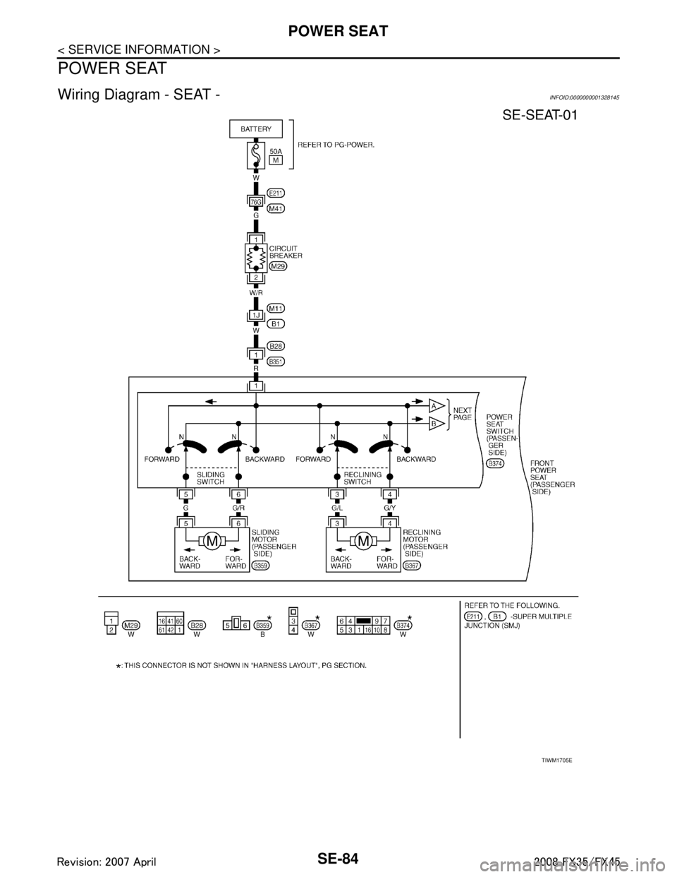
Wiring Diagram - SEAT -INFOID:0000000001328145
TIWM1705E
3AA93ABC3ACD3AC03ACA3AC03AC63AC53A913A773A893A873A873A8E3A773A983AC73AC93AC03AC3
3A893A873A873A8F3A773A9D3AAF3A8A3A8C3A863A9D3AAF3A8B3A8C
Page 3726 of 3924

HEATED SEATSE-87
< SERVICE INFORMATION >
C
DE
F
G H
J
K L
M A
B
SE
N
O P
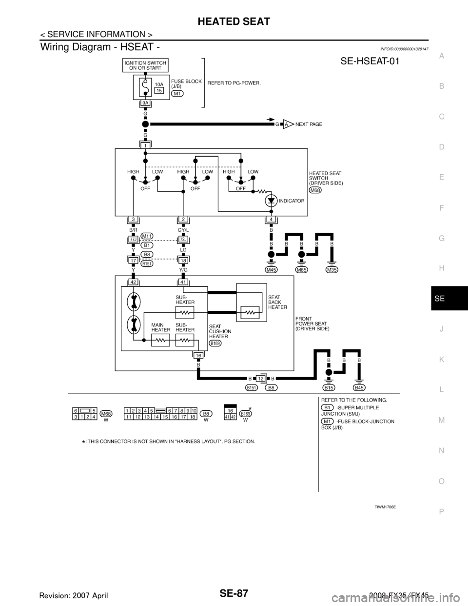
Wiring Diagram - HSEAT -INFOID:0000000001328147
TIWM1706E
3AA93ABC3ACD3AC03ACA3AC03AC63AC53A913A773A893A873A873A8E3A773A983AC73AC93AC03AC3
3A893A873A873A8F3A773A9D3AAF3A8A3A8C3A863A9D3AAF3A8B3A8C
Page 3738 of 3924

SRS-1
RESTRAINTS
C
DE
F
G
I
J
K L
M
SECTION SRS
A
B
SRS
N
O P
CONTENTS
SUPPLEMENTAL RESTRAINT SYSTEM (SRS)
SERVICE INFORMATION .. ..........................2
DTC INDEX ..................................................... .....2
B1001-B1015 ...................................................... ......2
B1017-B1035 ............................................................2
B1042-B1057 ............................................................3
B1058-B1073 ............................................................3
B1074-B1089 ............................................................4
B1106-B1120 ............................................................4
B1122-B1137 ............................................................5
B1138-B1153 ............................................................5
B1202-B1210 ............................................................5
PRECAUTIONS ...................................................7
Precaution for Supplemental Restraint System
(SRS) "AIR BAG" and "SEAT BELT PRE-TEN-
SIONER" ............................................................. ......
7
Precaution for SRS "AIR BAG" and "SEAT BELT
PRE-TENSIONER" Service ......................................
7
Occupant Classification System Precaution .............7
PREPARATION ...................................................8
Commercial Service Tool .................................... ......8
SUPPLEMENTAL RESTRAINT SYSTEM
(SRS) ...................................................................
9
SRS Configuration .............................................. ......9
Front Seat Belt Pre-tensioner with Load Limiter .....10
Front Side Air Bag ...................................................10
Side Curtain Air Bag ................................................10
Occupant Classification System (OCS) ..................10
Passenger Air Bag Status Condition .......................11
Component Parts of Occupant Classification Sys-
tem ..........................................................................
11
TROUBLE DIAGNOSIS .....................................12
Trouble Diagnosis Introduction ........................... ....12
Component Parts Location ......................................14
Schematic ...............................................................15
Wiring Diagram - SRS - ...........................................16
CONSULT-III Function ........................................
....21
Self-Diagnosis Function (Without CONSULT-III) .....22
SRS Operation Check .............................................23
Trouble Diagnosis with CONSULT-III ......................24
Trouble Diagnosis without CONSULT-III .................28
Trouble Diagnosis: "AIR BAG" Warning Lamp
Does Not Turn OFF .................................................
32
Trouble Diagnosis: "AIR BAG" Warning Lamp
Does Not Turn ON ...................................................
32
DRIVER AIR BAG MODULE ............................34
Removal and Installation .........................................34
SPIRAL CABLE ................................................36
Removal and Installation .........................................36
FRONT PASSENGER AIR BAG MODULE ......38
Removal and Installation .........................................38
SIDE CURTAIN AIR BAG MODULE ................40
Removal and Installation .........................................40
CRASH ZONE SENSOR ...................................42
Removal and Installation ..................................... ....42
SIDE AIR BAG (SATELLITE) SENSOR ...........43
Removal and Installation .........................................43
DIAGNOSIS SENSOR UNIT .............................44
Removal and Installation .........................................44
FRONT SEAT BELT PRE-TENSIONER ...........45
Removal and Installation .........................................45
OCCUPANT CLASSIFICATION SYSTEM
CONTROL UNIT ................................................
46
Removal and Installation .........................................46
COLLISION DIAGNOSIS ..................................47
For Frontal Collision ................................................47
For Side Collision ....................................................48
3AA93ABC3ACD3AC03ACA3AC03AC63AC53A913A773A893A873A873A8E3A773A983AC73AC93AC03AC3
3A893A873A873A8F3A773A9D3AAF3A8A3A8C3A863A9D3AAF3A8B3A8C
Page 3749 of 3924

SRS-12
< SERVICE INFORMATION >
TROUBLE DIAGNOSIS
TROUBLE DIAGNOSIS
Trouble Diagnosis IntroductionINFOID:0000000001524161
CAUTION:
Do not use electrical test equipment on any circuit related to the SRS unless instructed in this Ser-
vice Manual. SRS wiring harnesses can be identifi ed by yellow and/or orange harnesses or harness
connectors.
Do not repair, splice or modify the SRS wiring harn ess. If the harness is damaged, replace it with a
new one.
Keep ground portion clean.
DIAGNOSIS FUNCTION
The SRS self-diagnostic results can be read by us ing “AIR BAG” warning lamp and/or CONSULT-III.
The User mode is exclusively prepared for the customer (driver). This mode warns the driver of a system mal-
function through the operation of the “AIR BAG” warning lamp.
The Diagnosis mode allows the technician to locate and inspect the malfunctioning part.
The mode applications for the “AIR BAG” wa rning lamp and CONSULT-III are as follows:
HOW TO PERFORM TROUBLE DIAGNOSIS FOR QUICK AND ACCURATE REPAIR
A good understanding of the malfunction conditions can make troubleshooting faster and more accurate.
In general, each customer feels differently about a malf unction. It is important to fully understand the symp-
toms or conditions for a customer complaint.
Information from Customer
WHAT..... Vehicle model
WHEN..... Date, Frequencies
WHERE..... Road conditions
HOW..... Operating conditions, Symptoms
Preliminary Check
Make sure the following parts are in good order.
Battery (Refer to SC-4, "
How to Handle Battery".)
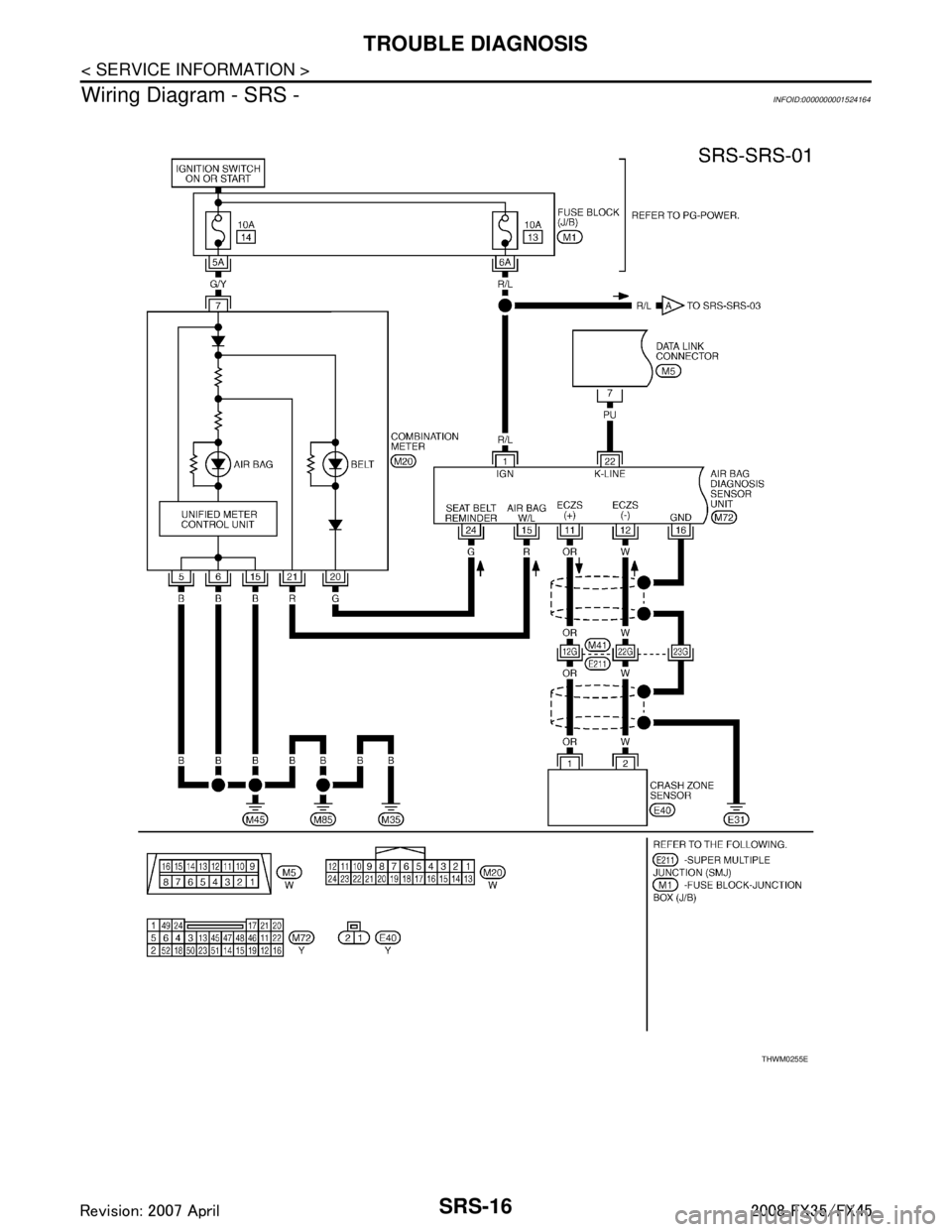
Fuse (Refer to SRS-16, "
Wiring Diagram - SRS -".)
System component-to-harness connections
Work Flow
OVERALL SEQUENCE
User mode Diagnosis mode Display type
“AIR BAG” warning lamp X X ON-OFF operation CONSULT-III — X Monitoring
3AA93ABC3ACD3AC03ACA3AC03AC63AC53A913A773A893A873A873A8E3A773A983AC73AC93AC03AC3
3A893A873A873A8F3A773A9D3AAF3A8A3A8C3A863A9D3AAF3A8B3A8C
Page 3753 of 3924

SRS-16
< SERVICE INFORMATION >
TROUBLE DIAGNOSIS
Wiring Diagram - SRS -
INFOID:0000000001524164
THWM0255E
3AA93ABC3ACD3AC03ACA3AC03AC63AC53A913A773A893A873A873A8E3A773A983AC73AC93AC03AC3
3A893A873A873A8F3A773A9D3AAF3A8A3A8C3A863A9D3AAF3A8B3A8C
Page 3787 of 3924

TF-1
DRIVELINE/AXLE
CEF
G H
I
J
K L
M
SECTION TF
A
B
TF
N
O P
CONTENTS
TRANSFER
SERVICE INFORMATION .. ..........................3
DTC INDEX ..................................................... .....3
C1201-C1210, U1000 ......................................... ......3
PRECAUTIONS ...................................................4
Precaution for Supplemental Restraint System
(SRS) "AIR BAG" and "SEAT BELT PRE-TEN-
SIONER" ............................................................. ......
4
Precaution .................................................................4
Service Notice or Precaution .....................................5
PREPARATION ...................................................6
Special Service Tool ........................................... ......6
Commercial Service Tool ..........................................7
NOISE, VIBRATION AND HARSHNESS
(NVH) TROUBLESHOOTING .............................
9
NVH Troubleshooting Chart ................................ ......9
TRANSFER FLUID .............................................10
Replacement ....................................................... ....10
Inspection ................................................................10
AWD SYSTEM ................................................ ....11
Power Transfer Diagram ..................................... ....11
System Description .................................................11
Schematic ...............................................................13
CAN Communication ...............................................13
TROUBLE DIAGNOSIS .....................................14
Fail-Safe Function ............................................... ....14
How to Perform Trouble Diagnosis .........................14
Location of Electrical Parts ......................................15
Circuit Diagram .......................................................16
Wiring Diagram - AWD - ..........................................17
Trouble Diagnosis Chart by Symptom ....................20
AWD Control Unit Input/Output Signal Reference
Value ................................................................... ....
20
CONSULT-III Function (ALL MODE AWD/4WD) ....21
TROUBLE DIAGNOSIS FOR SYSTEM .............24
DTC C1201 CONTROLLER FAILURE ................ ....24
DTC C1203 ABS SYSTEM ......................................24
DTC C1204 4WD SOLENOID ............................. ....25
DTC C1205 4WD ACTUATOR RLY ........................27
DTC C1210 ENGINE SIGNAL 1 ..............................28
DTC U1000 CAN COMM CIRCUIT .........................28
Power Supply Circuit for AWD Control Unit .............28
TROUBLE DIAGNOSIS FOR SYMPTOMS ......30
AWD Warning Lamp Does Not Turn ON When the
Ignition Switch Is Turned to ON ...............................
30
AWD Warning Lamp Does Not Turn OFF Several
Seconds after Engine Started ..................................
30
Heavy Tight-Corner Braking Symptom Occurs
When the Vehicle Is Driven and the Steering
Wheel Is Turned Fully to Either Side after the En-
gine Is Started .........................................................
32
Vehicle Does Not Enter AWD Mode Even Though
AWD Warning Lamp Turned to OFF .......................
33
While Driving, AWD Warning Lamp Flashes Rap-
idly (When Flashing in Approx. 1 Minute and Then
Turning OFF) ....................................................... ....
33
While Driving, AWD Warning Lamp Flashes Slow-
ly (When Continuing to Flash until Turning Ignition
Switch OFF) .............................................................
33
AWD CONTROL UNIT ......................................35
Removal and Installation .........................................35
FRONT OIL SEAL .............................................36
Removal and Installation .........................................36
REAR OIL SEAL ...............................................37
Removal and Installation .........................................37
AIR BREATHER HOSE ....................................39
Removal and Installation .........................................39
TRANSFER ASSEMBLY ..................................40
Removal and Installation .........................................40
Disassembly and Assembly .....................................40
3AA93ABC3ACD3AC03ACA3AC03AC63AC53A913A773A893A873A873A8E3A773A983AC73AC93AC03AC3
3A893A873A873A8F3A773A9D3AAF3A8A3A8C3A863A9D3AAF3A8B3A8C
Page 3803 of 3924

TROUBLE DIAGNOSISTF-17
< SERVICE INFORMATION >
CEF
G H
I
J
K L
M A
B
TF
N
O P
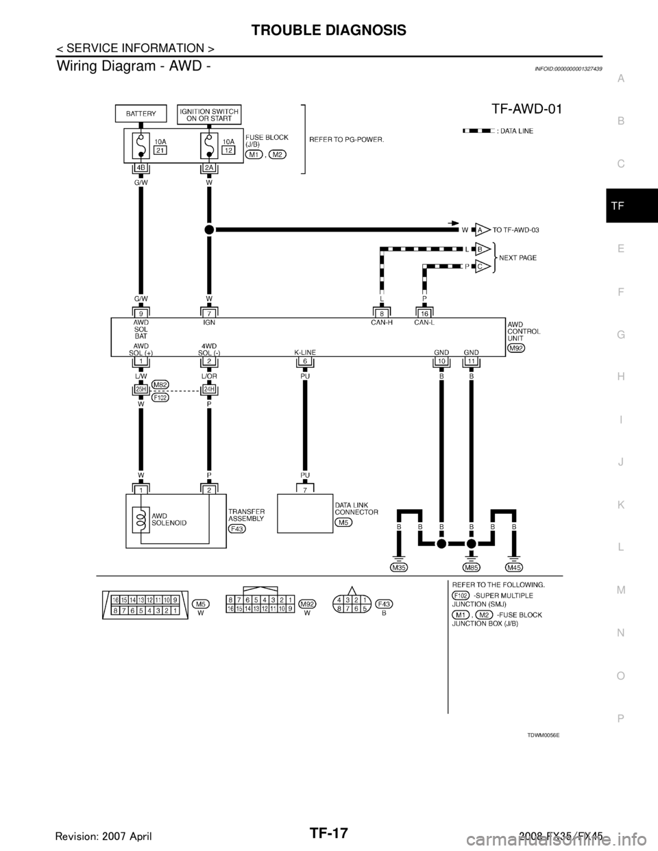
Wiring Diagram - AWD -INFOID:0000000001327439
TDWM0056E
3AA93ABC3ACD3AC03ACA3AC03AC63AC53A913A773A893A873A873A8E3A773A983AC73AC93AC03AC3
3A893A873A873A8F3A773A9D3AAF3A8A3A8C3A863A9D3AAF3A8B3A8C
Page 3841 of 3924

WT-1
SUSPENSION
C
DF
G H
I
J
K L
M
SECTION WT
A
B
WT
N
O PCONTENTS
ROAD WHEELS & TIRES
SERVICE INFORMATION .. ..........................2
INDEX FOR DTC ............................................ .....2
DTC No. Index .................................................... ......2
PRECAUTIONS ...................................................3
Precaution for Supplemental Restraint System
(SRS) "AIR BAG" and "SEAT BELT PRE-TEN-
SIONER" ............................................................. ......
3
Precaution .................................................................3
Service Notice or Precaution .....................................4
PREPARATION ...................................................5
Special Service Tool ........................................... ......5
Commercial Service Tool ..........................................5
NOISE, VIBRATION AND HARSHNESS
(NVH) TROUBLESHOOTING .............................
6
NVH Troubleshooting Chart ................................ ......6
ROAD WHEEL ....................................................7
Inspection ............................................................ ......7
ROAD WHEEL TIRE ASSEMBLY ......................8
Balancing Wheels (Bonding Weight Type) .......... ......8
Tire Rotation ..............................................................9
TIRE PRESSURE MONITORING SYSTEM .......10
System Component ............................................. ....10
System Description .................................................10
CAN COMMUNICATION ....................................13
System Description ............................................. ....13
TROUBLE DIAGNOSES ....................................14
Schematic ........................................................... ....14
Wiring Diagram- T/WARN - .....................................15
Control Unit Input/Output Signal Standard ..............17
ID Registration Procedure ................................... ....19
Transmitter Wake Up Operation ..............................20
Self-Diagnosis .........................................................20
CONSULT-III Function (BCM) .................................22
How to Perform Trouble Diagnosis for Quick and
Accurate Repair .......................................................
24
Preliminary Check ...................................................25
Malfunction Code/Symptom Chart ...........................26
TROUBLE DIAGNOSIS FOR SELF-DIAG-
NOSTIC ITEMS .................................................
28
Transmitter or Control Unit (BCM) ...........................28
Transmitter - 1 .........................................................28
Transmitter - 2 .........................................................29
Vehicle Speed Signal ..............................................29
TROUBLE DIAGNOSIS FOR SYMPTOMS ......30
Low Tire Pressure Warning Lamp Does Not Come
On When Ignition Switch Is Turned On ...................
30
Low Tire Pressure Warning Lamp Stays On When
Ignition Switch Is Turned On ............................... ....
30
Low Tire Pressure Warning Lamp Blinks When Ig-
nition Switch Is Turned On ......................................
31
Run-Flat Tire Warning Lamp Stays On When Igni-
tion Switch Is Turned On .........................................
32
Turn Signal Lamp Blinks When Ignition Switch Is
Turned On ...............................................................
32
ID Registration Cannot Be Completed ....................32
REMOVAL AND INSTALLATION .....................33
Transmitter ..............................................................33
SERVICE DATA AND SPECIFICATIONS
(SDS) .................................................................
35
Road Wheel .............................................................35
Tire ..........................................................................35
3AA93ABC3ACD3AC03ACA3AC03AC63AC53A913A773A893A873A873A8E3A773A983AC73AC93AC03AC3
3A893A873A873A8F3A773A9D3AAF3A8A3A8C3A863A9D3AAF3A8B3A8C