Page 3528 of 3924
SUNROOFRF-13
< SERVICE INFORMATION >
C
DE
F
G H
J
K L
M A
B
RF
N
O P
Wiring Diagram - SROOF -INFOID:0000000001328037
TIWM1691E
3AA93ABC3ACD3AC03ACA3AC03AC63AC53A913A773A893A873A873A8E3A773A983AC73AC93AC03AC3
3A893A873A873A8F3A773A9D3AAF3A8A3A8C3A863A9D3AAF3A8B3A8C
Page 3602 of 3924

SEAT BELTSSB-3
< SERVICE INFORMATION >
C
DE
F
G
I
J
K L
M A
B
SB
N
O P
SEAT BELTS
System DescriptionINFOID:0000000001327734
SEAT BELT WARNING CHIME
With ignition switch turned ON and seat belt unfastened (seat belt switch ON), warning chime will sound for
approximately 6 seconds.
If warning chime does not sound, refer to DI-61, "
Symptom Chart" in DI section.
SEAT BELT WARNING LAMP
Fasten driver's seat belt.
The seat belt warning lamp should go out.
If the seat belt warning lamp does not go out, refer to DI-36, "
Wiring Diagram - WARN -".
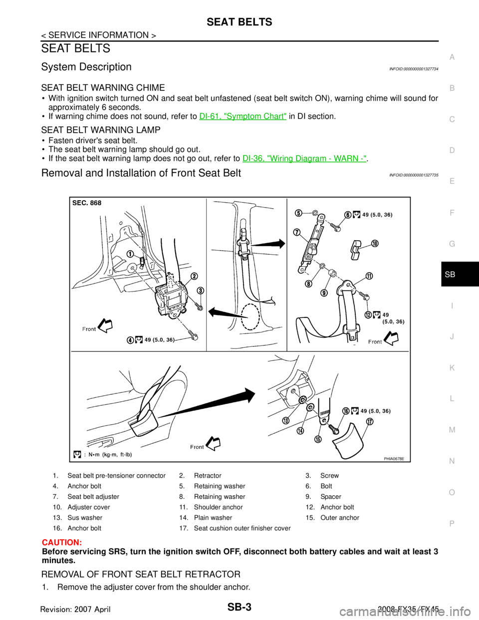
Removal and Installation of Front Seat BeltINFOID:0000000001327735
CAUTION:
Before servicing SRS, turn the igni tion switch OFF, disconnect both ba ttery cables and wait at least 3
minutes.
REMOVAL OF FRONT SEAT BELT RETRACTOR
1. Remove the adjuster cover from the shoulder anchor.
1. Seat belt pre-tensioner connector 2. Retractor 3. Screw
4. Anchor bolt 5. Retaining washer 6. Bolt
7. Seat belt adjuster 8. Retaining washer 9. Spacer
10. Adjuster cover 11. Shoulder anchor 12. Anchor bolt
13. Sus washer 14. Plain washer 15. Outer anchor
16. Anchor bolt 17. Seat cushion outer finisher cover
PHIA0678E
3AA93ABC3ACD3AC03ACA3AC03AC63AC53A913A773A893A873A873A8E3A773A983AC73AC93AC03AC3
3A893A873A873A8F3A773A9D3AAF3A8A3A8C3A863A9D3AAF3A8B3A8C
Page 3610 of 3924

SC-1
ELECTRICAL
C
DE
F
G H
I
J
L
M
SECTION SC
A
B
SC
N
O P
CONTENTS
STARTING & CHARGING SYSTEM
SERVICE INFORMATION .. ..........................2
PRECAUTIONS .............................................. .....2
Precaution for Supplemental Restraint System
(SRS) "AIR BAG" and "SEAT BELT PRE-TEN-
SIONER" ............................................................. ......
2
PREPARATION ...................................................3
Special Service Tools .......................................... ......3
Commercial Service Tools ........................................3
BATTERY ............................................................4
How to Handle Battery ........................................ ......4
Trouble Diagnosis with Battery Service Center .........6
Removal and Installation ...........................................6
STARTING SYSTEM ...........................................8
System Description ............................................. ......8
Wiring Diagram - START - ........................................9
Trouble Diagnosis with Starting/Charging System
Tester (Starting) ......................................................
10
Removal and Installation (VK45DE Engine Mod-
els) ..........................................................................
13
Removal and Installation [VQ35DE Engine Mod-
els (2WD)] ............................................................ ....
14
Removal and Installation [VQ35DE Engine Mod-
els (AWD)] ...............................................................
15
Disassembly and Assembly .....................................15
Inspection After Disassembly ..................................18
CHARGING SYSTEM .......................................19
System Description ..................................................19
Wiring Diagram - CHARGE - ...................................20
Trouble Diagnosis with Starting/Charging System
Tester (Charging) ....................................................
21
Removal and Installation (VK45DE Engine Mod-
els) ...........................................................................
25
Removal and Installation (VQ35DE Engine Mod-
els) ...........................................................................
27
Disassembly and Assembly .....................................28
SERVICE DATA AND SPECIFICATIONS
(SDS) .................................................................
30
Battery .....................................................................30
Starter ......................................................................30
Alternator .................................................................30
3AA93ABC3ACD3AC03ACA3AC03AC63AC53A913A773A893A873A873A8E3A773A983AC73AC93AC03AC3
3A893A873A873A8F3A773A9D3AAF3A8A3A8C3A863A9D3AAF3A8B3A8C
Page 3618 of 3924
STARTING SYSTEMSC-9
< SERVICE INFORMATION >
C
DE
F
G H
I
J
L
M A
B
SC
N
O P
Wiring Diagram - START -INFOID:0000000001328247
VK45DE ENGINE MODELS
TKWM1275E
3AA93ABC3ACD3AC03ACA3AC03AC63AC53A913A773A893A873A873A8E3A773A983AC73AC93AC03AC3
3A893A873A873A8F3A773A9D3AAF3A8A3A8C3A863A9D3AAF3A8B3A8C
Page 3629 of 3924
SC-20
< SERVICE INFORMATION >
CHARGING SYSTEM
Wiring Diagram - CHARGE -
INFOID:0000000001328255
VK45DE ENGINE MODELS
TKWM4287E
3AA93ABC3ACD3AC03ACA3AC03AC63AC53A913A773A893A873A873A8E3A773A983AC73AC93AC03AC3
3A893A873A873A8F3A773A9D3AAF3A8A3A8C3A863A9D3AAF3A8B3A8C
Page 3640 of 3924

SE-1
BODY
C
DE
F
G H
J
K L
M
SECTION SE
A
B
SE
N
O P
CONTENTS
SEAT
SERVICE INFORMATION .. ..........................3
DTC INDEX ..................................................... .....3
U1000 .................................................................. ......3
B2112-B2128 ............................................................3
PRECAUTIONS ...................................................4
Precaution for Supplemental Restraint System
(SRS) "AIR BAG" and "SEAT BELT PRE-TEN-
SIONER" ............................................................. ......
4
Service Notice ...........................................................4
PREPARATION ...................................................5
Special Service Tool ........................................... ......5
Commercial Service Tool ..........................................5
SQUEAK AND RATTLE TROUBLE DIAG-
NOSES ................................................................
6
Work Flow ........................................................... ......6
Generic Squeak and Rattle Troubleshooting ............8
Diagnostic Worksheet .............................................10
AUTOMATIC DRIVE POSITIONER ...................12
System Description ............................................. ....12
Component Parts and Harness Connector Loca-
tion ..........................................................................
16
CAN Communication System Description ...............17
CAN Communication Unit .......................................17
Schematic ...............................................................18
Wiring Diagram - AUT/DP - .....................................20
Terminal and Reference Value for BCM .................32
Terminal and Reference Value for Automatic
Drive Positioner Control Unit ...................................
32
Terminal and Reference Value for Driver Seat
Control Unit .............................................................
34
Work Flow ...............................................................37
Preliminary Check ...................................................37
CONSULT-III Function (AUTO DRIVE POS.) .........40
Check CAN Communication System ......................42
Symptom Chart .......................................................43
Check Sliding Motor Circuit .....................................44
Check Reclining Motor Circuit ............................. ....45
Check Front Lifting Motor Circuit .............................46
Check Rear Lifting Motor Circuit ..............................47
Check Telescopic Motor Circuit ...............................48
Check Tilt Motor Circuit ...........................................49
Check Driver Side Mirror Motor Circuit ....................50
Check Passenger Side Mirror Motor Circuit ............52
Check Sliding Sensor Circuit ...................................53
Check Reclining Sensor Circuit ...............................54
Check Front Lifting Sensor Circuit ...........................55
Check Rear Lifting Sensor Circuit ...........................56
Check Telescopic Sensor Circuit .............................57
Check Tilt Sensor Circuit .........................................58
Check Driver Side Mirror Sensor Circuit ..................59
Check Passenger Side Mirror Sensor Circuit ..........60
Check Steering and Door Mirror Sensor Power
Supply and Ground Circuit .................................. ....
61
Check Front Door Switch (Driver Side) Circuit ........62
Check Sliding Switch Circuit ....................................63
Check Reclining Switch Circuit ................................64
Check Front Lifting Switch Circuit ............................66
Check Rear Lifting Switch Circuit ............................67
Check Power Seat Switch Ground Circuit ...............68
Check Telescopic Switch Circuit .............................68
Check Tilt Switch Circuit ..........................................70
Check Door Mirror Remote Control Switch
(Changeover Switch) Circuit ................................ ....
71
Check Door Mirror Remote Control Switch (Mirror
Switch) Circuit ...................................................... ....
73
Check A/T Device (Park Position Switch) Circuit ....74
Check Key Switch Circuit (With Intelligent Key) ......76
Check Key Switch Circuit (Without Intelligent Key) ....77
Check Seat Memory Switch Circuit ..................... ....78
Check Seat Memory Indicator Lamp Circuit ............79
Check UART Communication Line Circuit ...............80
Check Lumbar Support Circuit ............................ ....82
POWER SEAT ...................................................84
Wiring Diagram - SEAT - .........................................84
HEATED SEAT .................................................86
3AA93ABC3ACD3AC03ACA3AC03AC63AC53A913A773A893A873A873A8E3A773A983AC73AC93AC03AC3
3A893A873A873A8F3A773A9D3AAF3A8A3A8C3A863A9D3AAF3A8B3A8C
Page 3641 of 3924
SE-2
Description ..............................................................86
Wiring Diagram - HSEAT - .....................................87
FRONT SEAT ................................................. ...89
Removal and Installation ...................................... ...89
REAR SEAT ......................................................95
Removal and Installation ...................................... ...95
3AA93ABC3ACD3AC03ACA3AC03AC63AC53A913A773A893A873A873A8E3A773A983AC73AC93AC03AC3
3A893A873A873A8F3A773A9D3AAF3A8A3A8C3A863A9D3AAF3A8B3A8C
Page 3659 of 3924
SE-20
< SERVICE INFORMATION >
AUTOMATIC DRIVE POSITIONER
Wiring Diagram - AUT/DP -
INFOID:0000000001328102
TIWM1694E
3AA93ABC3ACD3AC03ACA3AC03AC63AC53A913A773A893A873A873A8E3A773A983AC73AC93AC03AC3
3A893A873A873A8F3A773A9D3AAF3A8A3A8C3A863A9D3AAF3A8B3A8C