Page 3604 of 3924

SEAT BELTSSB-5
< SERVICE INFORMATION >
C
DE
F
G
I
J
K L
M A
B
SB
N
O P
Removal and Installati on of Rear Seat BeltINFOID:0000000001327736
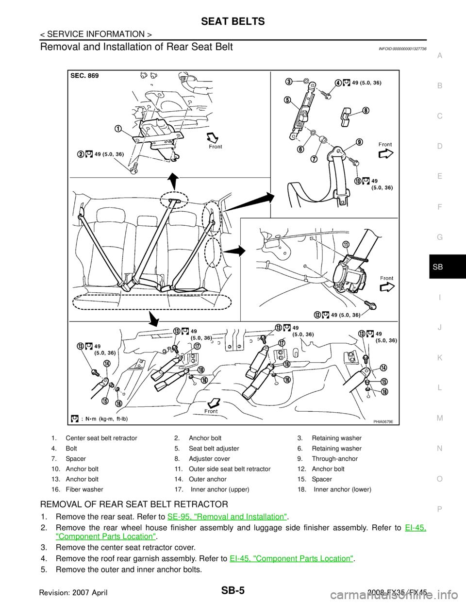
REMOVAL OF REAR SEAT BELT RETRACTOR
1. Remove the rear seat. Refer to SE-95, "Removal and Installation".
2. Remove the rear wheel house finisher assembly and luggage side finisher assembly. Refer to EI-45,
"Component Parts Location".
3. Remove the center seat retractor cover.
4. Remove the roof rear garnish assembly. Refer to EI-45, "
Component Parts Location".
5. Remove the outer and inner anchor bolts.
1. Center seat belt retractor 2. Anchor bolt 3. Retaining washer
4. Bolt 5. Seat belt adjuster 6. Retaining washer
7. Spacer 8. Adjuster cover 9. Through-anchor
10. Anchor bolt 11. Outer side seat belt retractor 12. Anchor bolt
13. Anchor bolt 14. Outer anchor 15. Spacer
16. Fiber washer 17. Inner anchor (upper) 18. Inner anchor (lower)
PHIA0679E
3AA93ABC3ACD3AC03ACA3AC03AC63AC53A913A773A893A873A873A8E3A773A983AC73AC93AC03AC3
3A893A873A873A8F3A773A9D3AAF3A8A3A8C3A863A9D3AAF3A8B3A8C
Page 3771 of 3924

SRS-34
< SERVICE INFORMATION >
DRIVER AIR BAG MODULE
DRIVER AIR BAG MODULE
Removal and InstallationINFOID:0000000001327764
WARNING:
Before servicing SRS, turn ignition switch OFF, disconnect both ba ttery cables and wait at least 3
minutes.
Always work from the side of driver air bag module.
Do not use air tools or el ectric tools for servicing.
REMOVAL
1. Remove the side lids.
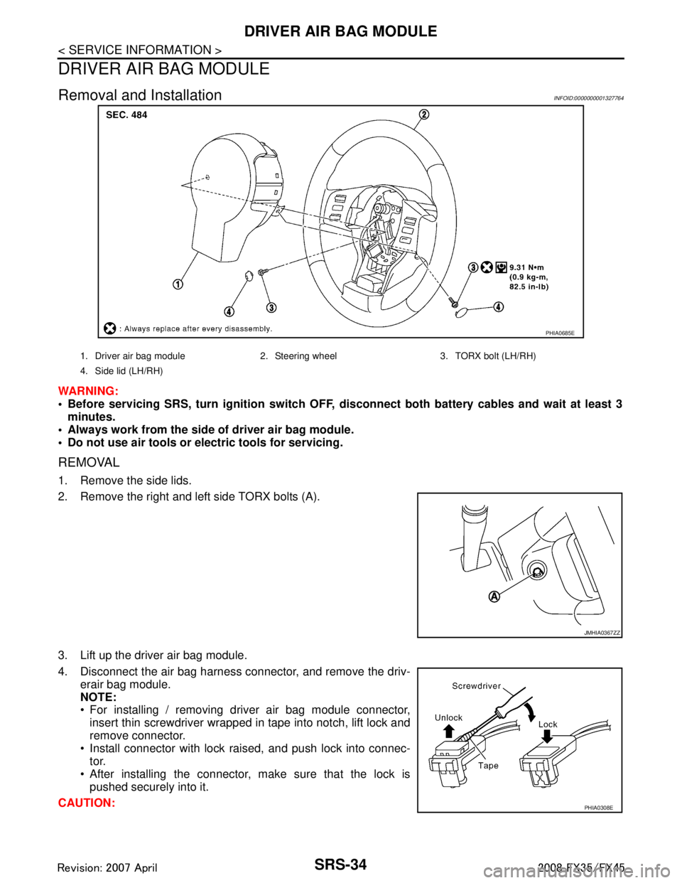
2. Remove the right and left side TORX bolts (A).
3. Lift up the driver air bag module.
4. Disconnect the air bag harness connector, and remove the driv-
erair bag module.
NOTE:
For installing / removing driver air bag module connector,insert thin screwdriver wrapped in tape into notch, lift lock and
remove connector.
Install connector with lock raised, and push lock into connec- tor.
After installing the connector, make sure that the lock is pushed securely into it.
CAUTION:
PHIA0685E
1. Driver air bag module 2. Steering wheel 3. TORX bolt (LH/RH)
4. Side lid (LH/RH)
JMHIA0367ZZ
PHIA0308E
3AA93ABC3ACD3AC03ACA3AC03AC63AC53A913A773A893A873A873A8E3A773A983AC73AC93AC03AC3
3A893A873A873A8F3A773A9D3AAF3A8A3A8C3A863A9D3AAF3A8B3A8C
Page 3772 of 3924

DRIVER AIR BAG MODULESRS-35
< SERVICE INFORMATION >
C
DE
F
G
I
J
K L
M A
B
SRS
N
O P
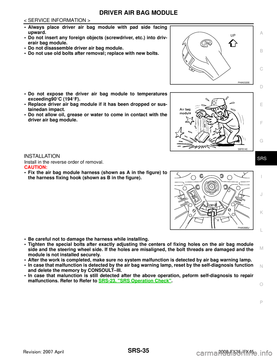
Always place driver air bag module with pad side facing upward.
Do not insert any foreign objects (screwdriver, etc.) into driv-
erair bag module.
Do not disassemble driver air bag module.
Do not use old bolts after removal; replace with new bolts.
Do not expose the driver air bag module to temperatures exceeding90 °C (194 °F).
Replace driver air bag module if it has been dropped or sus-
tainedan impact.
Do not allow oil, grease or water to come in contact with the
driver air bag module.
INSTALLATION
Install in the reverse order of removal.
CAUTION:
Fix the air bag module harness (shown as A in the figure) to
the harness fixing hook (s hown as B in the figure).
Be careful not to damage the harness while installing.
Tighten the special bolts after exactly adjusting the centers of fi xing holes on the air bag module
side and the steering wheel side. If the holes are misaligned, the bolt threads are damaged and the
module is not installed securely.
After the work is completed, make sure no system malfunction is detected by air bag warning lamp.
In case that malfunction is detected by the air ba g warning lamp, reset by the self-diagnosis function
and delete the memory by CONSOULT–III.
In case that malunction is still detected after th e above operation, peform self-diagnosis to repair
malfunctions. Refer to Refer to SRS-23, "
SRS Operation Check".
PHIA0320E
SBF814E
PHIA0885J
3AA93ABC3ACD3AC03ACA3AC03AC63AC53A913A773A893A873A873A8E3A773A983AC73AC93AC03AC3
3A893A873A873A8F3A773A9D3AAF3A8A3A8C3A863A9D3AAF3A8B3A8C