2008 INFINITI FX35 charging
[x] Cancel search: chargingPage 2395 of 3924
![INFINITI FX35 2008 Service Manual
FUEL PUMPEC-1155
< SERVICE INFORMATION > [VK45DE]
C
D
E
F
G H
I
J
K L
M A
EC
NP
O
FUEL PUMP
DescriptionINFOID:0000000001327057
SYSTEM DESCRIPTION
*: ECM determines the start signal status by the sign INFINITI FX35 2008 Service Manual
FUEL PUMPEC-1155
< SERVICE INFORMATION > [VK45DE]
C
D
E
F
G H
I
J
K L
M A
EC
NP
O
FUEL PUMP
DescriptionINFOID:0000000001327057
SYSTEM DESCRIPTION
*: ECM determines the start signal status by the sign](/manual-img/42/57017/w960_57017-2394.png)
FUEL PUMPEC-1155
< SERVICE INFORMATION > [VK45DE]
C
D
E
F
G H
I
J
K L
M A
EC
NP
O
FUEL PUMP
DescriptionINFOID:0000000001327057
SYSTEM DESCRIPTION
*: ECM determines the start signal status by the signals of engine speed and battery voltage.
The ECM activates the fuel pump for several seconds after the ignition switch is turned ON to improve engine
startability. If the ECM receives a engine speed signal
from the camshaft position sensor (PHASE), it knows
that the engine is rotating, and causes the pump to operate. If the engine speed signal is not received when
the ignition switch is ON, the engine stalls. The EC M stops pump operation and prevents battery discharging,
thereby improving safety. The ECM does not directly dr ive the fuel pump. It controls the ON/OFF fuel pump
relay, which in turn controls the fuel pump.
COMPONENT DESCRIPTION
A turbine type design fuel pump is used in the fuel tank.
CONSULT-III Reference Val ue in Data Monitor ModeINFOID:0000000001327058
Specification data are reference values.
Sensor Input signal to ECM ECM Function Actuator
Crankshaft position sensor (POS)
Camshaft position sensor (PHASE) Engine speed*
Fuel pump control Fuel pump relay
Battery Battery voltage*
Condition Fuel pump operation
Ignition switch is turned to ON. Operates for 1 second.
Engine running and cranking Operates.
When engine is stopped Stops in 1.5 seconds.
Except as shown above Sto ps .
PBIB1508E
MONITOR ITEM CONDITION SPECIFICATION
FUEL PUMP RLY For 1 seconds after turning ignition switch: ON
Engine running or cranking
ON
Except above OFF
3AA93ABC3ACD3AC03ACA3AC03AC63AC53A913A773A893A873A873A8E3A773A983AC73AC93AC03AC3
3A893A873A873A8F3A773A9D3AAF3A8A3A8C3A863A9D3AAF3A8B3A8C
Page 2779 of 3924
![INFINITI FX35 2008 Service Manual
FAX-14
< SERVICE INFORMATION >[AWD]
FRONT DRIVE SHAFT
14. Apply the specified amount of grease (NISSAN genuine grease
or equivalent) inside joint sub-assembly serration hole until
grease begins to oo INFINITI FX35 2008 Service Manual
FAX-14
< SERVICE INFORMATION >[AWD]
FRONT DRIVE SHAFT
14. Apply the specified amount of grease (NISSAN genuine grease
or equivalent) inside joint sub-assembly serration hole until
grease begins to oo](/manual-img/42/57017/w960_57017-2778.png)
FAX-14
< SERVICE INFORMATION >[AWD]
FRONT DRIVE SHAFT
14. Apply the specified amount of grease (NISSAN genuine grease
or equivalent) inside joint sub-assembly serration hole until
grease begins to ooze from ball groove and serration hole. After
applying grease, use a shop cloth to wipe off old grease that has
oozed out.
15. Wrap serration on shaft with tape to protect the boot from dam- age. Install new boot and boot bands to shaft.
16. Remove the tape wrapped around the serration on shaft.
17. Position circular clip on groove at the shaft edge. Align both counter axles of the shaft edge and joint sub-assembly. Then,
assemble shaft with circular clip onto joint sub-assembly.
NOTE:
Drive joint inserter (suitable tool) is recommended when install-
ing circular clip.
18. Install joint sub-assembly to shaft using plastic hammer. CAUTION:
Confirm that joint sub-assembly is correctly engaged while
rotating drive shaft.
19. Apply the balance of the spec ified amount of grease (NISSAN
genuine grease or equivalent) into the boot inside from large
diameter side of boot.
20. Install the boot securely into grooves (indicated by *marks) shown in the figure.
CAUTION:
If grease adheres to the boot mounting surface (with *mark)
on the shaft and joint sub- assembly, boot may come off.
Remove all grease from the surface.
21. To prevent from the deformation of the boot, adjust the boot installation length to the specified value shown below (L) by
inserting the flat-bladed screwdriv er into inside of the boot from
the large diameter side of the boot and discharging the inside
air.
SDIA2775E
SFA800
SDIA2490E
Grease amount : 77 – 97 g (2.71 – 3.42 oz)
SDIA2372E
SDIA1760E
3AA93ABC3ACD3AC03ACA3AC03AC63AC53A913A773A893A873A873A8E3A773A983AC73AC93AC03AC3
3A893A873A873A8F3A773A9D3AAF3A8A3A8C3A863A9D3AAF3A8B3A8C
Page 3343 of 3924

MA-26
< SERVICE INFORMATION >
CHASSIS AND BODY MAINTENANCE
CHASSIS AND BODY MAINTENANCE
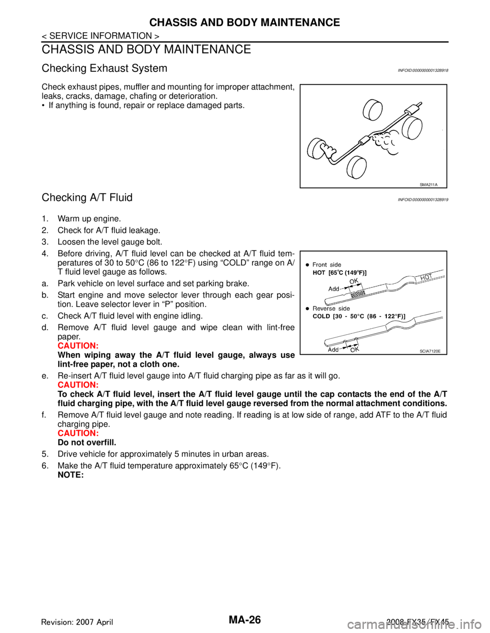
Checking Exhaust SystemINFOID:0000000001328918
Check exhaust pipes, muffler and mounting for improper attachment,
leaks, cracks, damage, chafing or deterioration.
If anything is found, repair or replace damaged parts.
Checking A/T FluidINFOID:0000000001328919
1. Warm up engine.
2. Check for A/T fluid leakage.
3. Loosen the level gauge bolt.
4. Before driving, A/T fluid level can be checked at A/T fluid tem-
peratures of 30 to 50 °C (86 to 122 °F) using “COLD” range on A/
T fluid level gauge as follows.
a. Park vehicle on level surface and set parking brake.
b. Start engine and move selector lever through each gear posi- tion. Leave selector lever in “P” position.
c. Check A/T fluid level with engine idling.
d. Remove A/T fluid level gauge and wipe clean with lint-free paper.
CAUTION:
When wiping away the A/T flui d level gauge, always use
lint-free paper, not a cloth one.
e. Re-insert A/T fluid level gauge into A/T fluid charging pipe as far as it will go. CAUTION:
To check A/T fluid level, insert the A/T fluid level gauge until the cap contacts the end of the A/T
fluid charging pipe, with the A/ T fluid level gauge reversed from the normal attachment conditions.
f. Remove A/T fluid level gauge and note reading. If reading is at low side of range, add ATF to the A/T fluid
charging pipe.
CAUTION:
Do not overfill.
5. Drive vehicle for approximately 5 minutes in urban areas.
6. Make the A/T fluid temperature approximately 65 °C (149 °F).
NOTE:
SMA211A
SCIA7120E
3AA93ABC3ACD3AC03ACA3AC03AC63AC53A913A773A893A873A873A8E3A773A983AC73AC93AC03AC3
3A893A873A873A8F3A773A9D3AAF3A8A3A8C3A863A9D3AAF3A8B3A8C
Page 3344 of 3924

CHASSIS AND BODY MAINTENANCEMA-27
< SERVICE INFORMATION >
C
DE
F
G H
I
J
K
M A
B
MA
N
O P
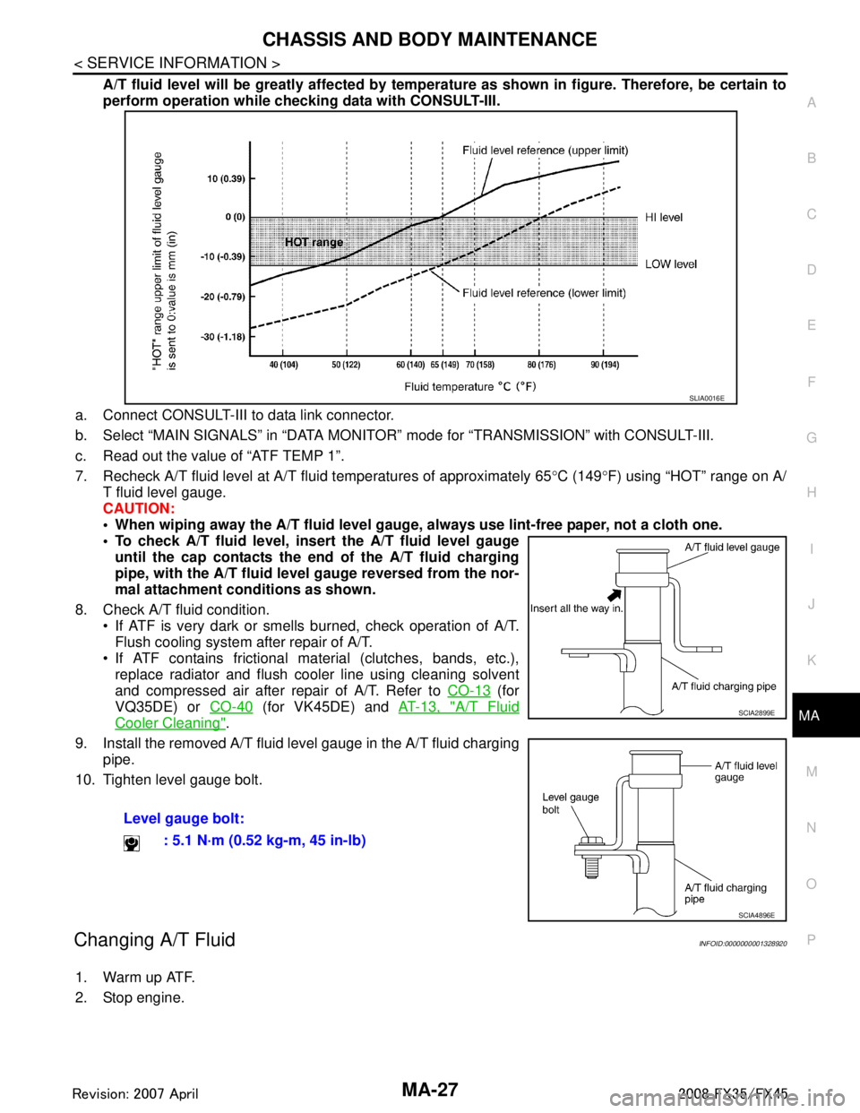
A/T fluid level will be greatly affected by temper ature as shown in figure. Therefore, be certain to
perform operation while checki ng data with CONSULT-III.
a. Connect CONSULT-III to data link connector.
b. Select “MAIN SIGNALS” in “DATA MONITOR” mode for “TRANSMISSION” with CONSULT-III.
c. Read out the value of “ATF TEMP 1”.
7. Recheck A/T fluid level at A/T fluid temperatures of approximately 65 °C (149 °F) using “HOT” range on A/
T fluid level gauge.
CAUTION:
When wiping away the A/T fluid level gauge, always use lint-free paper, not a cloth one.
To check A/T fluid level, inser t the A/T fluid level gauge
until the cap contacts the en d of the A/T fluid charging
pipe, with the A/T fluid level gauge reversed from the nor-
mal attachment conditions as shown.
8. Check A/T fluid condition. If ATF is very dark or smells burned, check operation of A/T.
Flush cooling system after repair of A/T.
If ATF contains frictional material (clutches, bands, etc.), replace radiator and flush cooler line using cleaning solvent
and compressed air after repair of A/T. Refer to CO-13
(for
VQ35DE) or CO-40
(for VK45DE) and AT-13, "A/T Fluid
Cooler Cleaning".
9. Install the removed A/T fluid level gauge in the A/T fluid charging pipe.
10. Tighten level gauge bolt.
Changing A/T FluidINFOID:0000000001328920
1. Warm up ATF.
2. Stop engine. Level gauge bolt:
: 5.1 N·m (0.52 kg-m, 45 in-lb)
SLIA0016E
SCIA2899E
SCIA4896E
3AA93ABC3ACD3AC03ACA3AC03AC63AC53A913A773A893A873A873A8E3A773A983AC73AC93AC03AC3
3A893A873A873A8F3A773A9D3AAF3A8A3A8C3A863A9D3AAF3A8B3A8C
Page 3345 of 3924

MA-28
< SERVICE INFORMATION >
CHASSIS AND BODY MAINTENANCE
3. Loosen the level gauge bolt.
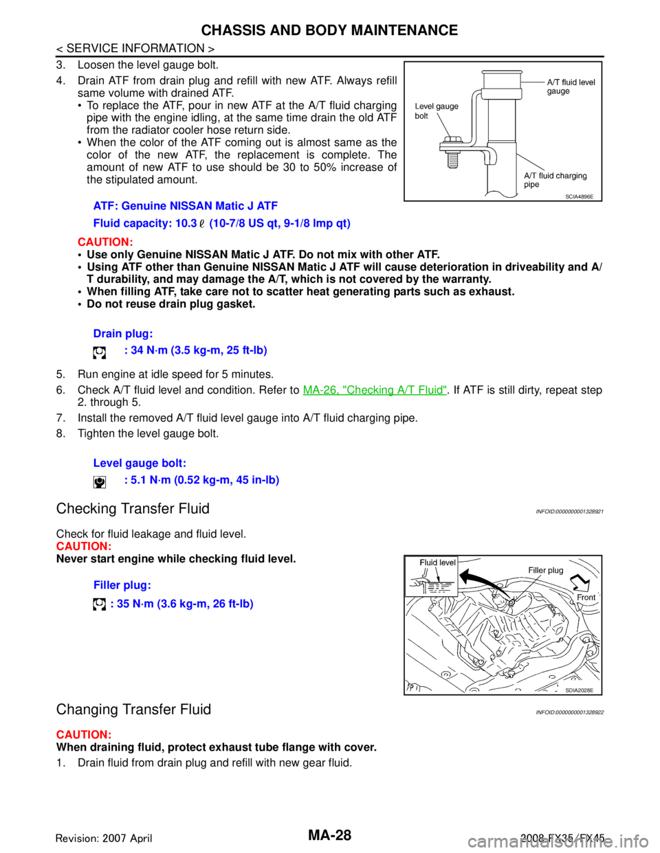
4. Drain ATF from drain plug and refill with new ATF. Always refillsame volume with drained ATF.
To replace the ATF, pour in new ATF at the A/T fluid charging
pipe with the engine idling, at the same time drain the old ATF
from the radiator cooler hose return side.
When the color of the ATF coming out is almost same as the color of the new ATF, the replacement is complete. The
amount of new ATF to use should be 30 to 50% increase of
the stipulated amount.
CAUTION:
Use only Genuine NISSAN Matic J ATF. Do not mix with other ATF.
Using ATF other than Genuine NISSAN Matic J AT F will cause deterioration in driveability and A/
T durability, and may damage the A/T, which is not covered by the warranty.
When filling ATF, take care not to scatter heat generating parts such as exhaust.
Do not reuse drain plug gasket.
5. Run engine at idle speed for 5 minutes.
6. Check A/T fluid level and condition. Refer to MA-26, "
Checking A/T Fluid". If ATF is still dirty, repeat step
2. through 5.
7. Install the removed A/T fluid level gauge into A/T fluid charging pipe.
8. Tighten the level gauge bolt.
Checking Transfer FluidINFOID:0000000001328921
Check for fluid leakage and fluid level.
CAUTION:
Never start engine while checking fluid level.
Changing Transfer FluidINFOID:0000000001328922
CAUTION:
When draining fluid, protect exh aust tube flange with cover.
1. Drain fluid from drain plug and refill with new gear fluid. ATF: Genuine NISSAN Matic J ATF
Fluid capacity: 10.3 (10-7/8 US qt, 9-1/8 lmp qt)
Drain plug:
: 34 N·m (3.5 kg-m, 25 ft-lb)
Level gauge bolt: : 5.1 N·m (0.52 kg-m, 45 in-lb)
SCIA4896E
Filler plug:
: 35 N·m (3.6 kg-m, 26 ft-lb)
SDIA2028E
3AA93ABC3ACD3AC03ACA3AC03AC63AC53A913A773A893A873A873A8E3A773A983AC73AC93AC03AC3
3A893A873A873A8F3A773A9D3AAF3A8A3A8C3A863A9D3AAF3A8B3A8C
Page 3425 of 3924

HARNESSPG-61
< SERVICE INFORMATION >
C
DE
F
G H
I
J
L
M A
B
PG
N
O P
Code Section Wiring Diagram Name
A/C ATC Air Conditioner
AF1B1 EC Air Fuel Ratio Sensor 1 Bank 1
AF1B2 EC Air Fuel Ratio Sensor 1 Bank 2
AF1HB1 EC Air Fuel Ratio Sensor 1 Heater Bank 1
AF1HB2 EC Air Fuel Ratio Sensor 1 Heater Bank 2
APPS1 EC Accelerator Pedal Position Sensor
APPS2 EC Accelerator Pedal Position Sensor
APPS3 EC Accelerator Pedal Position Sensor
ASC/BS EC Automatic Speed Control Device (ASCD) Brake Switch
ASC/SW EC Automatic Speed Control Device (ASCD) Steering Switch
ASCBOF EC Automatic Speed Control Device (ASCD) Brake Switch
ASCIND EC Automatic Speed Contro l Device (ASCD) Indicator
AT/IND DI A/T Indicator Lamp
AUDIO AV Audio
AUT/DP SE Automatic Drive Positioner
AUTO/L LT Automatic Light System
AWD TF AWD Control System
B/CLOS BL Back Door Closure System
BACK/L LT Back-Up Lamp
BRK/SW EC Brake Switch
CAN AT CAN Communication Line
CAN EC CAN Communication Line
CAN LAN CAN System
CHARGE SC Charging System
CHIME DI Warning Chime
CLOCK DI Clock
COMBSW LT Combination Switch
COMM AV Audio Visual Communication Line
COMPAS DI Compass
COOL/F EC Cooling Fan Control
D/LOCK BL Power Door Lock
DEF GW Rear Window Defogger
DTRL LT Headlamp - With Daytime Light System
ECM/PW EC ECM Power Supply for Back-Up
ECTS EC Engine Coolant Temperature Sensor
ETC1 EC Electric Throttle Control Function
ETC2 EC Electric Throttle Control Motor Relay
ETC3 EC Electric Throttle Control Motor
F/FOG LT Front Fog Lamp
F/PUMP EC Fuel Pump
FTS AT A/T Fluid Temperature Sensor Circuit
FTTS EC Fuel Tank Temperature Sensor
FUELB1 EC Fuel Injection System Function (Bank 1)
FUELB2 EC Fuel Injection System Function (Bank 2)
3AA93ABC3ACD3AC03ACA3AC03AC63AC53A913A773A893A873A873A8E3A773A983AC73AC93AC03AC3
3A893A873A873A8F3A773A9D3AAF3A8A3A8C3A863A9D3AAF3A8B3A8C
Page 3610 of 3924

SC-1
ELECTRICAL
C
DE
F
G H
I
J
L
M
SECTION SC
A
B
SC
N
O P
CONTENTS
STARTING & CHARGING SYSTEM
SERVICE INFORMATION .. ..........................2
PRECAUTIONS .............................................. .....2
Precaution for Supplemental Restraint System
(SRS) "AIR BAG" and "SEAT BELT PRE-TEN-
SIONER" ............................................................. ......
2
PREPARATION ...................................................3
Special Service Tools .......................................... ......3
Commercial Service Tools ........................................3
BATTERY ............................................................4
How to Handle Battery ........................................ ......4
Trouble Diagnosis with Battery Service Center .........6
Removal and Installation ...........................................6
STARTING SYSTEM ...........................................8
System Description ............................................. ......8
Wiring Diagram - START - ........................................9
Trouble Diagnosis with Starting/Charging System
Tester (Starting) ......................................................
10
Removal and Installation (VK45DE Engine Mod-
els) ..........................................................................
13
Removal and Installation [VQ35DE Engine Mod-
els (2WD)] ............................................................ ....
14
Removal and Installation [VQ35DE Engine Mod-
els (AWD)] ...............................................................
15
Disassembly and Assembly .....................................15
Inspection After Disassembly ..................................18
CHARGING SYSTEM .......................................19
System Description ..................................................19
Wiring Diagram - CHARGE - ...................................20
Trouble Diagnosis with Starting/Charging System
Tester (Charging) ....................................................
21
Removal and Installation (VK45DE Engine Mod-
els) ...........................................................................
25
Removal and Installation (VQ35DE Engine Mod-
els) ...........................................................................
27
Disassembly and Assembly .....................................28
SERVICE DATA AND SPECIFICATIONS
(SDS) .................................................................
30
Battery .....................................................................30
Starter ......................................................................30
Alternator .................................................................30
3AA93ABC3ACD3AC03ACA3AC03AC63AC53A913A773A893A873A873A8E3A773A983AC73AC93AC03AC3
3A893A873A873A8F3A773A9D3AAF3A8A3A8C3A863A9D3AAF3A8B3A8C
Page 3612 of 3924

PREPARATIONSC-3
< SERVICE INFORMATION >
C
DE
F
G H
I
J
L
M A
B
SC
N
O P
PREPARATION
Special Service ToolsINFOID:0000000001328241
Commercial Service ToolsINFOID:0000000001328242
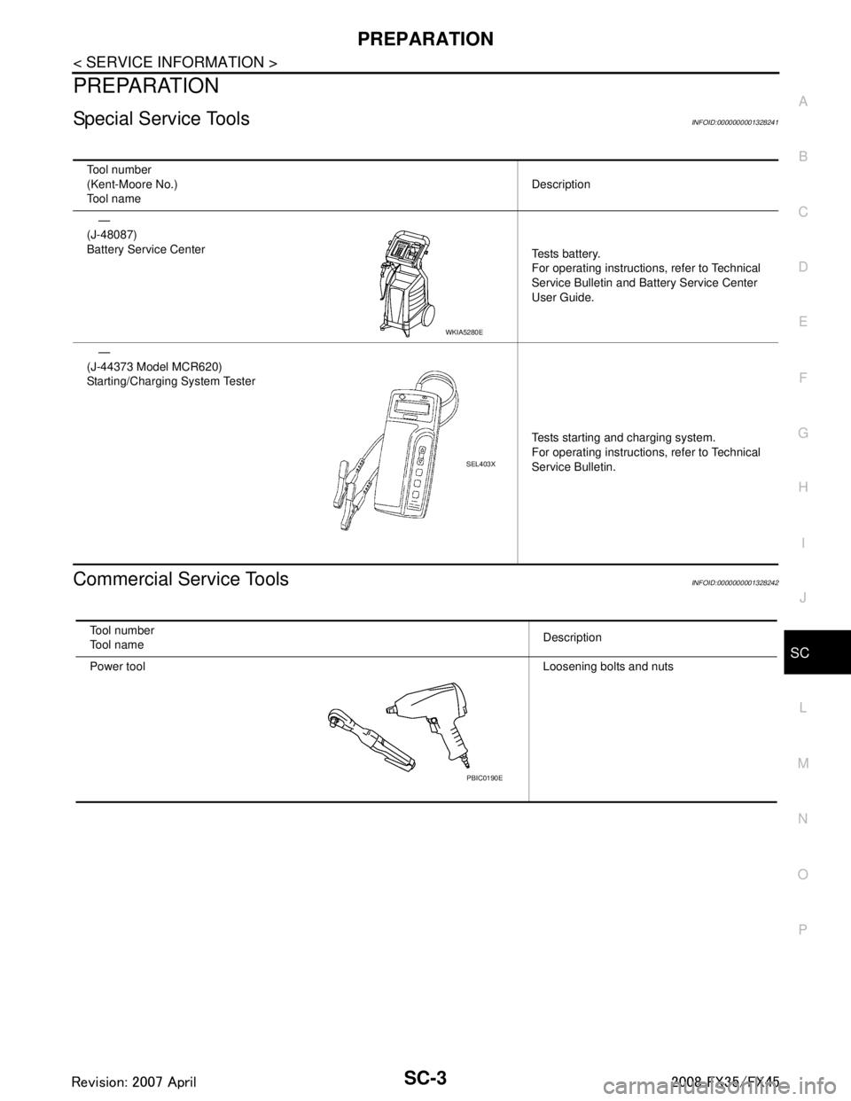
Tool number
(Kent-Moore No.)
Tool name Description
—
(J-48087)
Battery Service Center Tests battery.
For operating instructions, refer to Technical
Service Bulletin and Battery Service Center
User Guide.
—
(J-44373 Model MCR620)
Starting/Charging System Tester
Tests starting and charging system.
For operating instructions, refer to Technical
Service Bulletin.
WKIA5280E
SEL403X
Tool number
Tool name Description
Power tool Loosening bolts and nuts
PBIC0190E
3AA93ABC3ACD3AC03ACA3AC03AC63AC53A913A773A893A873A873A8E3A773A983AC73AC93AC03AC3
3A893A873A873A8F3A773A9D3AAF3A8A3A8C3A863A9D3AAF3A8B3A8C