Page 3613 of 3924

SC-4
< SERVICE INFORMATION >
BATTERY
BATTERY
How to Handle BatteryINFOID:0000000001328243
CAUTION:
If it becomes necessary to start the engine with a booster battery and jumper cables, use a 12-volt
booster battery.
After connecting battery cables, ensure that they are tightly clamped to battery terminals for good
contact.
METHODS OF PREVENTING OVER-DISCHARGE
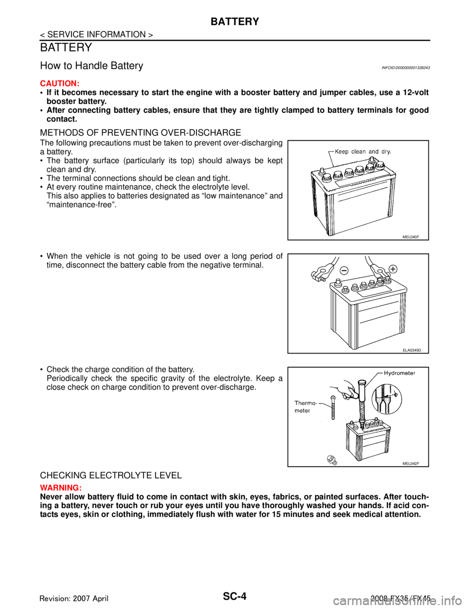
The following precautions must be taken to prevent over-discharging
a battery.
The battery surface (particularly its top) should always be kept clean and dry.
The terminal connections should be clean and tight.
At every routine maintenance, check the electrolyte level.
This also applies to batteries designated as “low maintenance” and
“maintenance-free”.
When the vehicle is not going to be used over a long period of time, disconnect the battery cable from the negative terminal.
Check the charge condition of the battery. Periodically check the specific gr avity of the electrolyte. Keep a
close check on charge condition to prevent over-discharge.
CHECKING ELECTROLYTE LEVEL
WARNING:
Never allow battery fluid to come in contact with skin, eyes, fabrics, or painted surfaces. After touch-
ing a battery, never touch or rub your eyes until you have thoroughly washed your hands. If acid con-
tacts eyes, skin or clothing, immediately flush wit h water for 15 minutes and seek medical attention.
MEL040F
ELA0349D
MEL042F
3AA93ABC3ACD3AC03ACA3AC03AC63AC53A913A773A893A873A873A8E3A773A983AC73AC93AC03AC3
3A893A873A873A8F3A773A9D3AAF3A8A3A8C3A863A9D3AAF3A8B3A8C
Page 3614 of 3924

BATTERYSC-5
< SERVICE INFORMATION >
C
DE
F
G H
I
J
L
M A
B
SC
N
O P
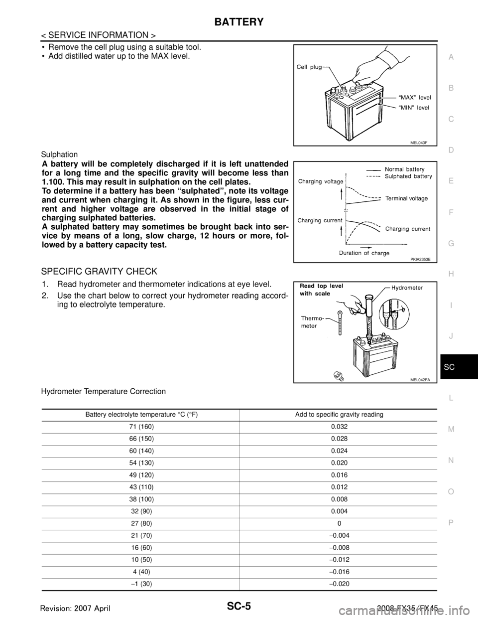
Remove the cell plug using a suitable tool.
Add distilled water up to the MAX level.
Sulphation
A battery will be completely discharged if it is left unattended
for a long time and the specific gravity will become less than
1.100. This may result in su lphation on the cell plates.
To determine if a battery has been “sulphated”, note its voltage
and current when charging it. As shown in the figure, less cur-
rent and higher voltage are observed in the initial stage of
charging sulphated batteries.
A sulphated battery may sometimes be brought back into ser-
vice by means of a long, slow charge, 12 hours or more, fol-
lowed by a battery capacity test.
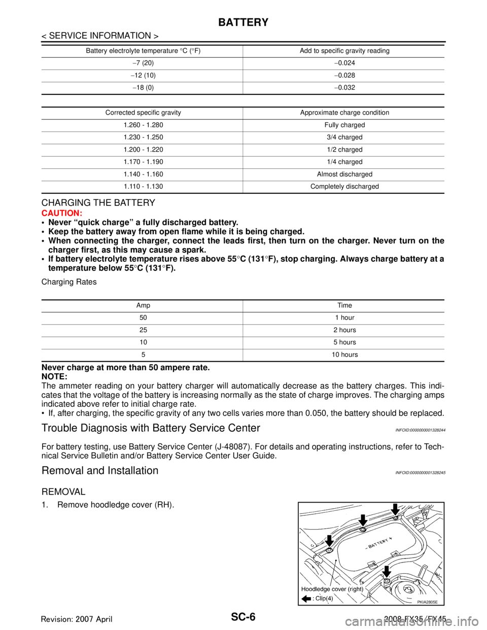
SPECIFIC GRAVITY CHECK
1. Read hydrometer and thermometer indications at eye level.
2. Use the chart below to correct your hydrometer reading accord- ing to electrolyte temperature.
Hydrometer Temperature Correction
MEL043F
PKIA2353E
MEL042FA
Battery electrolyte temperature °C ( °F) Add to specific gravity reading
71 (160) 0.032
66 (150) 0.028
60 (140) 0.024
54 (130) 0.020
49 (120) 0.016 43 (110) 0.012
38 (100) 0.008
32 (90) 0.004
27 (80) 0
21 (70) −0.004
16 (60) −0.008
10 (50) −0.012
4 (40) −0.016
− 1 (30) −0.020
3AA93ABC3ACD3AC03ACA3AC03AC63AC53A913A773A893A873A873A8E3A773A983AC73AC93AC03AC3
3A893A873A873A8F3A773A9D3AAF3A8A3A8C3A863A9D3AAF3A8B3A8C
Page 3615 of 3924

SC-6
< SERVICE INFORMATION >
BATTERY
CHARGING THE BATTERY
CAUTION:
Never “quick charge” a fully discharged battery.
Keep the battery away from open flame while it is being charged.
When connecting the charger, connect the leads first, then turn on the charger. Never turn on the
charger first, as this may cause a spark.
If battery electrolyte temperature rises above 55 °C (131 °F), stop charging. Always charge battery at a
temperature below 55 °C (131 °F).
Charging Rates
Never charge at more than 50 ampere rate.
NOTE:
The ammeter reading on your battery charger will automat ically decrease as the battery charges. This indi-
cates that the voltage of the battery is increasing norma lly as the state of charge improves. The charging amps
indicated above refer to initial charge rate.
If, after charging, the specific gravity of any two ce lls varies more than 0.050, the battery should be replaced.
Trouble Diagnosis with Battery Service CenterINFOID:0000000001328244
For battery testing, use Battery Service Center (J-48087) . For details and operating instructions, refer to Tech-
nical Service Bulletin and/or Battery Service Center User Guide.
Removal and InstallationINFOID:0000000001328245
REMOVAL
1. Remove hoodledge cover (RH).
− 7 (20) −0.024
− 12 (10) −0.028
− 18 (0) −0.032
Corrected specific gravity Approximate charge condition 1.260 - 1.280 Fully charged
1.230 - 1.250 3/4 charged
1.200 - 1.220 1/2 charged
1.170 - 1.190 1/4 charged
1.140 - 1.160 Almost discharged1.110 - 1.130 Completely discharged
Battery electrolyte temperature
°C ( °F) Add to specific gravity reading
Amp Time
50 1 hour
25 2 hours
10 5 hours5 10 hours
PKIA2805E
3AA93ABC3ACD3AC03ACA3AC03AC63AC53A913A773A893A873A873A8E3A773A983AC73AC93AC03AC3
3A893A873A873A8F3A773A9D3AAF3A8A3A8C3A863A9D3AAF3A8B3A8C
Page 3619 of 3924
SC-10
< SERVICE INFORMATION >
STARTING SYSTEM
VQ35DE ENGINE MODELS
Trouble Diagnosis with Starting/Charging System Tester (Starting)INFOID:0000000001328248
For starting system testing, use Starting/Charging Syst em Tester (J-44373). For details and operating instruc-
tions, refer to Technical Service Bulletin.
TKWM1276E
3AA93ABC3ACD3AC03ACA3AC03AC63AC53A913A773A893A873A873A8E3A773A983AC73AC93AC03AC3
3A893A873A873A8F3A773A9D3AAF3A8A3A8C3A863A9D3AAF3A8B3A8C
Page 3622 of 3924

STARTING SYSTEMSC-13
< SERVICE INFORMATION >
C
DE
F
G H
I
J
L
M A
B
SC
N
O P
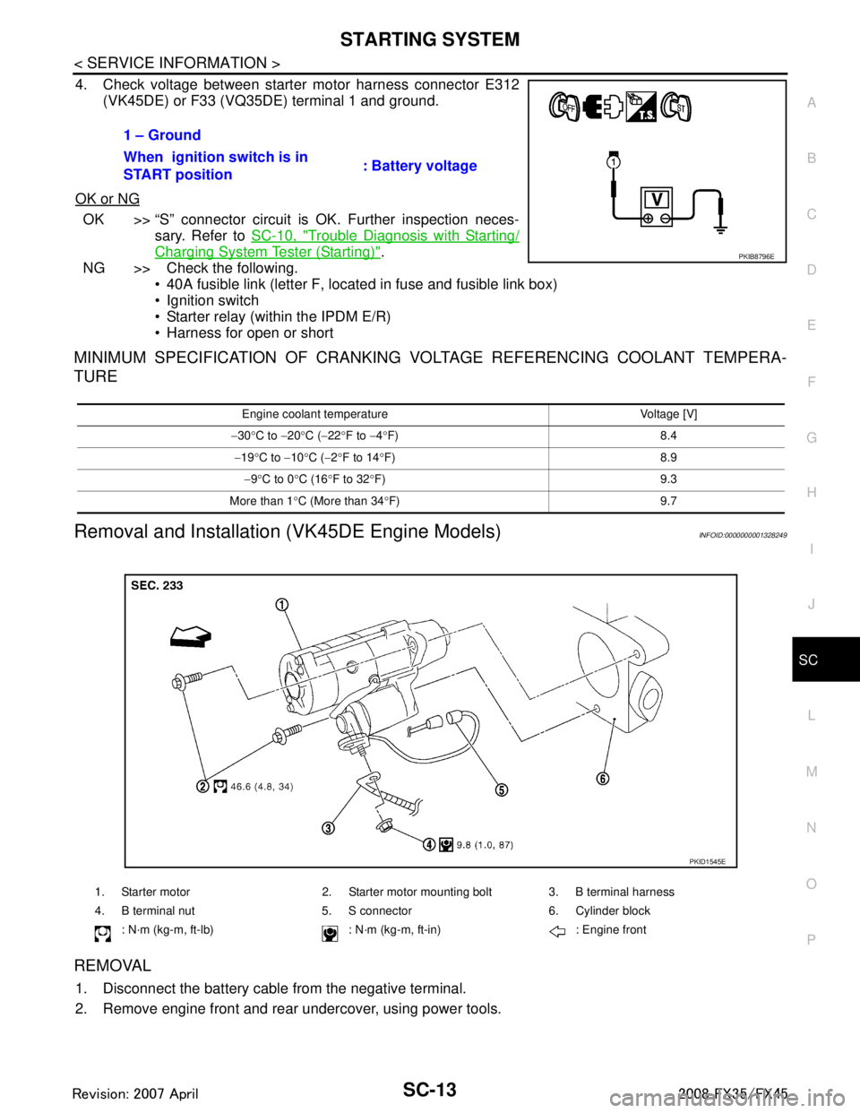
4. Check voltage between starter motor harness connector E312 (VK45DE) or F33 (VQ35DE) terminal 1 and ground.
OK or NG
OK >> “S” connector circuit is OK. Further inspection neces- sary. Refer to SC-10, "
Trouble Diagnosis with Starting/
Charging System Tester (Starting)".
NG >> Check the following.
40A fusible link (letter F, located in fuse and fusible link box)
Ignition switch
Starter relay (within the IPDM E/R)
Harness for open or short
MINIMUM SPECIFICATION OF CRANKING VO LTAGE REFERENCING COOLANT TEMPERA-
TURE
Removal and Installation (VK45DE Engine Models)INFOID:0000000001328249
REMOVAL
1. Disconnect the battery cable from the negative terminal.
2. Remove engine front and rear undercover, using power tools. 1 – Ground
When ignition switch is in
START position
: Battery voltage
PKIB8796E
Engine coolant temperature Voltage [V]
− 30 °C to −20 °C ( −22 °F to −4 °F) 8.4
− 19 °C to −10 °C ( −2 °F to 14 °F) 8.9
− 9 °C to 0 °C (16 °F to 32 °F) 9.3
More than 1 °C (More than 34 °F) 9.7
1. Starter motor 2. Starter motor mounting bolt 3. B terminal harness
4. B terminal nut 5. S connector 6. Cylinder block
: N·m (kg-m, ft-lb) : N·m (k g-m, ft-in) : Engine front
PKID1545E
3AA93ABC3ACD3AC03ACA3AC03AC63AC53A913A773A893A873A873A8E3A773A983AC73AC93AC03AC3
3A893A873A873A8F3A773A9D3AAF3A8A3A8C3A863A9D3AAF3A8B3A8C
Page 3628 of 3924

CHARGING SYSTEMSC-19
< SERVICE INFORMATION >
C
DE
F
G H
I
J
L
M A
B
SC
N
O P
CHARGING SYSTEM
System DescriptionINFOID:0000000001328254
The alternator provides DC voltage to operate the vehi cle's electrical system and to keep the battery charged.
The voltage output is controlled by the IC regulator.
Power is supplied at all times
through 10A fuse (No. 33, located in the fuse and fusible link block)
to alternator terminal 4 (“S” terminal).
“B” Terminal supplies power to charge the battery and oper ate the vehicle's electrical system. Output voltage
is controlled by the IC regulator at terminal 4 (“S” terminal) detecting the input voltage.
The charging circuit is protected by the 120A fusible link (VK45DE and VQ35DE AWD).
The alternator is grounded to the engine block.
With the ignition switch in the ON or START position, power is supplied
through 10A fuse [No. 14, located in the fuse block (J/B)]
to combination meter terminal 7 for the charge warning lamp.
Ground is supplied
to combination meter terminal 2
through alternator terminal 3 (“L” terminal)
to alternator terminal 2 (“E” terminal) (VK45DE) or through case ground (VQ35DE)
through ground E304 (VK45DE).
With power and ground supplied, the charge warning lamp will illuminate. When the alternator is providing suf-
ficient voltage with the engine running, the ground is opened and the charge warning lamp will go off.
If the charge warning lamp illuminates with the engine running, a malfunction is indicated.
MALFUNCTION INDICATOR
The IC regulator warning function activates to illumi nate charge warning lamp, if any of the following symp-
toms occur while alternator is operating:
Excessive voltage is produced.
No voltage is produced.
3AA93ABC3ACD3AC03ACA3AC03AC63AC53A913A773A893A873A873A8E3A773A983AC73AC93AC03AC3
3A893A873A873A8F3A773A9D3AAF3A8A3A8C3A863A9D3AAF3A8B3A8C
Page 3629 of 3924
SC-20
< SERVICE INFORMATION >
CHARGING SYSTEM
Wiring Diagram - CHARGE -
INFOID:0000000001328255
VK45DE ENGINE MODELS
TKWM4287E
3AA93ABC3ACD3AC03ACA3AC03AC63AC53A913A773A893A873A873A8E3A773A983AC73AC93AC03AC3
3A893A873A873A8F3A773A9D3AAF3A8A3A8C3A863A9D3AAF3A8B3A8C
Page 3630 of 3924
CHARGING SYSTEMSC-21
< SERVICE INFORMATION >
C
DE
F
G H
I
J
L
M A
B
SC
N
O P
VQ35DE ENGINE MODELS
Trouble Diagnosis with Starting/Ch arging System Tester (Charging)INFOID:0000000001328256
For charging system testing, use Starting/Chargi ng System Tester (J-44373). For details and operating
instructions, refer to Technical Service Bulletin.
TKWM4288E
3AA93ABC3ACD3AC03ACA3AC03AC63AC53A913A773A893A873A873A8E3A773A983AC73AC93AC03AC3
3A893A873A873A8F3A773A9D3AAF3A8A3A8C3A863A9D3AAF3A8B3A8C