Page 3726 of 3924
HEATED SEATSE-87
< SERVICE INFORMATION >
C
DE
F
G H
J
K L
M A
B
SE
N
O P
Wiring Diagram - HSEAT -INFOID:0000000001328147
TIWM1706E
3AA93ABC3ACD3AC03ACA3AC03AC63AC53A913A773A893A873A873A8E3A773A983AC73AC93AC03AC3
3A893A873A873A8F3A773A9D3AAF3A8A3A8C3A863A9D3AAF3A8B3A8C
Page 3728 of 3924
FRONT SEATSE-89
< SERVICE INFORMATION >
C
DE
F
G H
J
K L
M A
B
SE
N
O P
FRONT SEAT
Removal and InstallationINFOID:0000000001328148
CAUTION:
Do not disassembly the component parts of only fron t passenger seat in the dotted lines shown in the
figure below.
PIIB8524E
3AA93ABC3ACD3AC03ACA3AC03AC63AC53A913A773A893A873A873A8E3A773A983AC73AC93AC03AC3
3A893A873A873A8F3A773A9D3AAF3A8A3A8C3A863A9D3AAF3A8B3A8C
Page 3730 of 3924

FRONT SEATSE-91
< SERVICE INFORMATION >
C
DE
F
G H
J
K L
M A
B
SE
N
O P
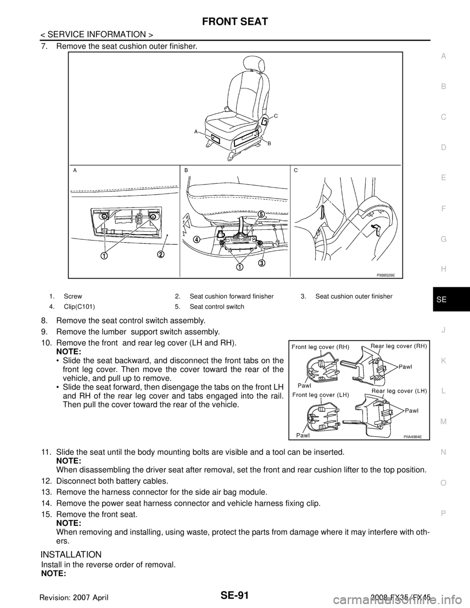
7. Remove the seat cushion outer finisher.
8. Remove the seat control switch assembly.
9. Remove the lumber support switch assembly.
10. Remove the front and rear leg cover (LH and RH). NOTE:
Slide the seat backward, and disconnect the front tabs on the
front leg cover. Then move the cover toward the rear of the
vehicle, and pull up to remove.
Slide the seat forward, then disengage the tabs on the front LH and RH of the rear leg cover and tabs engaged into the rail.
Then pull the cover toward the rear of the vehicle.
11. Slide the seat until the body mounting bolts are visible and a tool can be inserted. NOTE:
When disassembling the driver seat after removal, set the front and rear cushion lifter to the top position.
12. Disconnect both battery cables.
13. Remove the harness connector for the side air bag module.
14. Remove the power seat harness connector and vehicle harness fixing clip.
15. Remove the front seat. NOTE:
When removing and installing, using waste, protect t he parts from damage where it may interfere with oth-
ers.
INSTALLATION
Install in the reverse order of removal.
NOTE:
PIIB8526E
1. Screw 2. Seat cushion forward finisher 3. Seat cushion outer finisher
4. Clip(C101) 5. Seat control switch
PIIA4984E
3AA93ABC3ACD3AC03ACA3AC03AC63AC53A913A773A893A873A873A8E3A773A983AC73AC93AC03AC3
3A893A873A873A8F3A773A9D3AAF3A8A3A8C3A863A9D3AAF3A8B3A8C
Page 3732 of 3924
FRONT SEATSE-93
< SERVICE INFORMATION >
C
DE
F
G H
J
K L
M A
B
SE
N
O P
6. Remove the heated seat connector.
7. After removing the seatback trim and pad, remove t he hog rings to separate the trim, pad, and seatback
heater unit.
INSTALLATION OF SEATBACK TRIM AND PAD
Install in the reverse order of removal.
REMOVAL OF SEAT CUSHION TRIM AND PAD
CAUTION:
Do not disassemble the component parts of only fron t passenger seat in the dotted lines shown in the
figure. Refer to "Removal and Installation".
1. Remove the seat cushion inner finisher.
2. Remove the velcro and retainer.
3. Remove the seat harness connector.
4. Remove the seatback frame.
5. Remove the reclining device assembly.
PIIA6049E
PIIA6052E
PIIA6053E
PIIA6054E
3AA93ABC3ACD3AC03ACA3AC03AC63AC53A913A773A893A873A873A8E3A773A983AC73AC93AC03AC3
3A893A873A873A8F3A773A9D3AAF3A8A3A8C3A863A9D3AAF3A8B3A8C
Page 3734 of 3924
REAR SEATSE-95
< SERVICE INFORMATION >
C
DE
F
G H
J
K L
M A
B
SE
N
O P
REAR SEAT
Removal and InstallationINFOID:0000000001328149
PIIB8527E
1. Headrest (side) 2. Headrest holder (free) 3. Headrest holder (locked)
4. Seatback trim (RH) 5. Seatback pad (RH) 6. Seatback frame (RH)
7. Nut 8. Seat hinge cover (RH) 9. Screw
10. Reclining lever (RH) 11. Reclining device outer cover (RH) 12. Reclining device inner cover (RH)
3AA93ABC3ACD3AC03ACA3AC03AC63AC53A913A773A893A873A873A8E3A773A983AC73AC93AC03AC3
3A893A873A873A8F3A773A9D3AAF3A8A3A8C3A863A9D3AAF3A8B3A8C
Page 3736 of 3924

REAR SEATSE-97
< SERVICE INFORMATION >
C
DE
F
G H
J
K L
M A
B
SE
N
O P
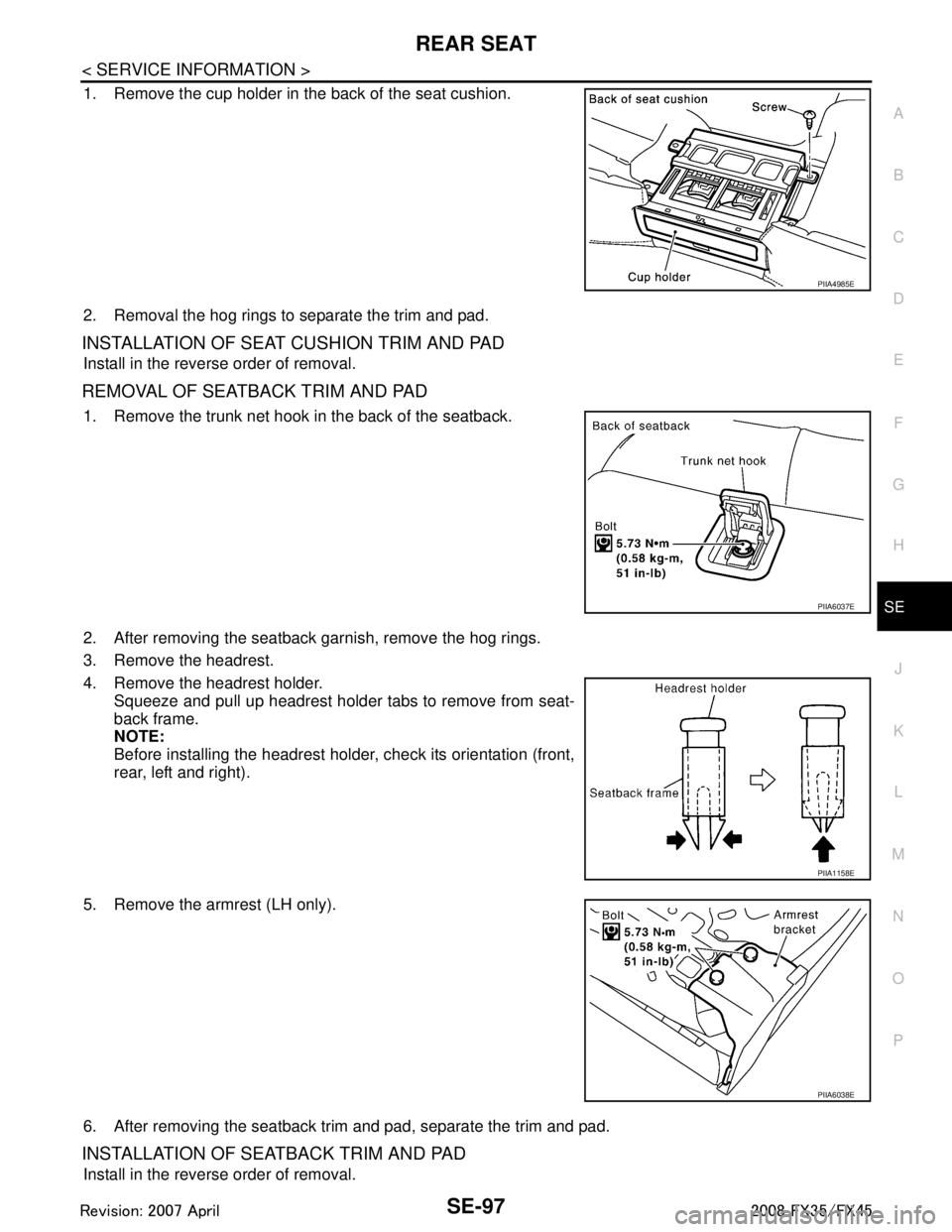
1. Remove the cup holder in the back of the seat cushion.
2. Removal the hog rings to separate the trim and pad.
INSTALLATION OF SEAT CUSHION TRIM AND PAD
Install in the reverse order of removal.
R E M O VA L O F S E AT B A C K T R I M A N D PA D
1. Remove the trunk net hook in the back of the seatback.
2. After removing the seatback garnish, remove the hog rings.
3. Remove the headrest.
4. Remove the headrest holder. Squeeze and pull up headrest holder tabs to remove from seat-
back frame.
NOTE:
Before installing the headrest holder, check its orientation (front,
rear, left and right).
5. Remove the armrest (LH only).
6. After removing the seatback trim and pad, separate the trim and pad.
INSTALLATION OF SEATBACK TRIM AND PAD
Install in the reverse order of removal.
PIIA4985E
PIIA6037E
PIIA1158E
PIIA6038E
3AA93ABC3ACD3AC03ACA3AC03AC63AC53A913A773A893A873A873A8E3A773A983AC73AC93AC03AC3
3A893A873A873A8F3A773A9D3AAF3A8A3A8C3A863A9D3AAF3A8B3A8C