2008 INFINITI FX35 power steering fluid
[x] Cancel search: power steering fluidPage 3463 of 3924

PS-8
< SERVICE INFORMATION >
POWER STEERING FLUID
6. Stop engine, check fluid level.
3AA93ABC3ACD3AC03ACA3AC03AC63AC53A913A773A893A873A873A8E3A773A983AC73AC93AC03AC3
3A893A873A873A8F3A773A9D3AAF3A8A3A8C3A863A9D3AAF3A8B3A8C
Page 3464 of 3924
STEERING WHEELPS-9
< SERVICE INFORMATION >
C
DE
F
H I
J
K L
M A
B
PS
N
O P
STEERING WHEEL
On-Vehicle Inspection and ServiceINFOID:0000000001327712
CHECKING CONDITION OF INSTALLATION
Check installation condition of steering gear assemb ly, front suspension, axle and steering column.
Check if movement exists when steering wheel is mo ved up and down, to the left and right and to the axial
direction.
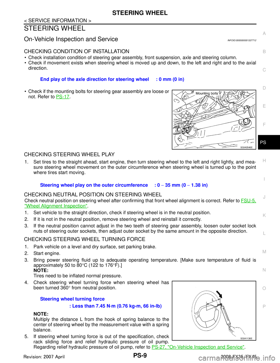
Check if the mounting bolts for steering gear assembly are loose or not. Refer to PS-17
.
CHECKING STEERING WHEEL PLAY
1. Set tires to the straight ahead, start engine, then turn steering wheel to the left and right lightly, and mea-
sure steering wheel movement on the outer circumfe rence when steering wheel is turned up to the point
where tires start moving.
CHECKING NEUTRAL POSITION ON STEERING WHEEL
Check neutral position on steering wheel after confirming that front wheel alignment is correct. Refer to FSU-5,
"Wheel Alignment Inspection".
1. Set vehicle to the straight direction, chec k if steering wheel is in the neutral position.
2. If it is not in the neutral position, remo ve steering wheel and reinstall it correctly.
3. If the neutral position cannot adjust in the two teeth of steering gear assembly, loosen outer socket lock
nuts of steering outer sockets, then adjust outer so cket by the same amount in the opposite direction.
CHECKING STEERING WHEEL TURNING FORCE
1. Park vehicle on a level and dry surface, set parking brake.
2. Start engine.
3. Bring power steering fluid up to adequate operating te mperature. [Make sure temperature of fluid is
approximately 50 to 80 °C (122 to 176 °F).]
NOTE:
Tires need to be inflated normal pressure.
4. Check steering wheel turning force when steering wheel has been turned 360 ° from neutral position.
NOTE:
Multiply the distance L from the hook of spring balance to the
center of steering wheel by the measurement value with a spring
balance.
5. If steering wheel turning force is out of the specification, check
rack sliding force and relief hydraulic pressure of oil pump.
Regarding relief hydraulic pressure of oil pump, refer to PS-27, "
On-Vehicle Inspection and Service".
End play of the axle direction for steering wheel : 0 mm (0 in)
SGIA0546E
Steering wheel play on the
outer circumference : 0 − 35 mm (0 − 1.38 in)
Steering wheel turning force : Less than 7.45 N·m (0.76 kg-m, 66 in-lb)
SGIA1136E
3AA93ABC3ACD3AC03ACA3AC03AC63AC53A913A773A893A873A873A8E3A773A983AC73AC93AC03AC3
3A893A873A873A8F3A773A9D3AAF3A8A3A8C3A863A9D3AAF3A8B3A8C
Page 3473 of 3924
PS-18
< SERVICE INFORMATION >
POWER STEERING GEAR AND LINKAGE
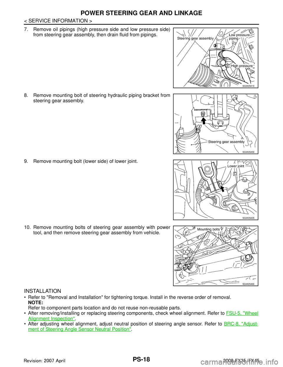
7. Remove oil pipings (high pressure side and low pressure side)from steering gear assembly, then drain fluid from pipings.
8. Remove mounting bolt of steering hydraulic piping bracket from steering gear assembly.
9. Remove mounting bolt (lower side) of lower joint.
10. Remove mounting bolts of steering gear assembly with power tool, and then remove steering gear assembly from vehicle.
INSTALLATION
Refer to "Removal and Installation" for tightening torque. Install in the reverse order of removal.
NOTE:
Refer to component parts location and do not reuse non-reusable parts.
After removing/installing or replacing steering components, check wheel alignment. Refer to FSU-5, "
Wheel
Alignment Inspection".
After adjusting wheel alignment, adjust neutral position of steering angle sensor. Refer to BRC-8, "
Adjust-
ment of Steering Angle Sensor Neutral Position".
SGIA0541E
SGIA0545E
SGIA0542E
SGIA0546E
3AA93ABC3ACD3AC03ACA3AC03AC63AC53A913A773A893A873A873A8E3A773A983AC73AC93AC03AC3
3A893A873A873A8F3A773A9D3AAF3A8A3A8C3A863A9D3AAF3A8B3A8C
Page 3475 of 3924
PS-20
< SERVICE INFORMATION >
POWER STEERING GEAR AND LINKAGE
CAUTION:
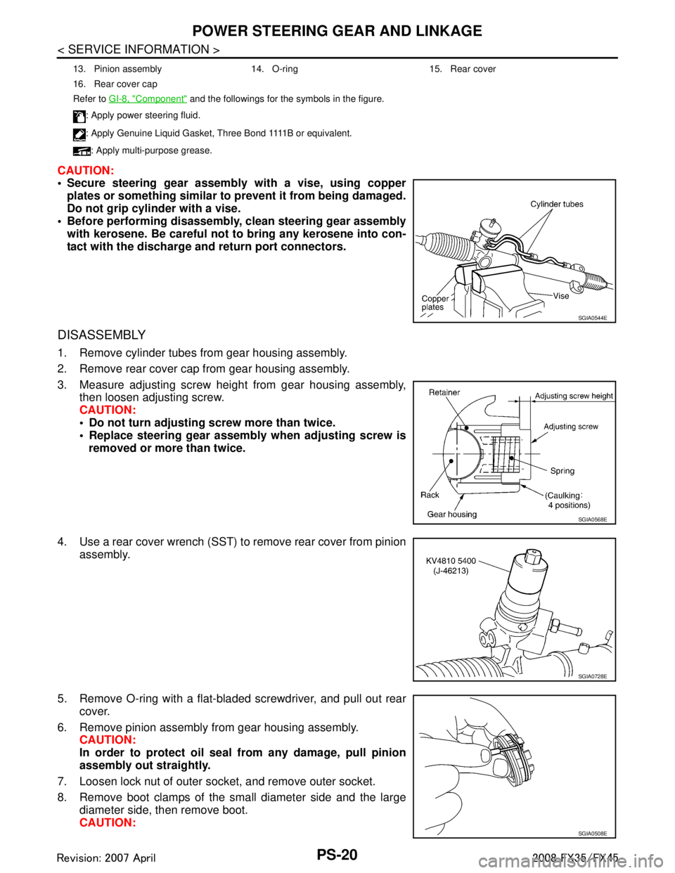
Secure steering gear assembly with a vise, using copperplates or something similar to prevent it from being damaged.
Do not grip cylinder with a vise.
Before performing disassembly, clean steering gear assembly
with kerosene. Be careful not to bring any kerosene into con-
tact with the discharge an d return port connectors.
DISASSEMBLY
1. Remove cylinder tubes from gear housing assembly.
2. Remove rear cover cap from gear housing assembly.
3. Measure adjusting screw height from gear housing assembly,
then loosen adjusting screw.
CAUTION:
Do not turn adjusting screw more than twice.
Replace steering gear assembly when adjusting screw is
removed or more than twice.
4. Use a rear cover wrench (SST) to remove rear cover from pinion assembly.
5. Remove O-ring with a flat-bladed screwdriver, and pull out rear cover.
6. Remove pinion assembly from gear housing assembly. CAUTION:
In order to protect oil seal from any damage, pull pinion
assembly out straightly.
7. Loosen lock nut of outer socket, and remove outer socket.
8. Remove boot clamps of the small diameter side and the large diameter side, then remove boot.
CAUTION:
13. Pinion assembly 14. O-ring 15. Rear cover
16. Rear cover cap
Refer to GI-8, "
Component" and the followings for the symbols in the figure.
: Apply power steering fluid.
: A p p l y G e n u i n e L i q u i d G a s k e t , T h r e e B o n d 1111 B o r e q u i v a l e n t .
: Apply multi-purpose grease.
SGIA0544E
SGIA0568E
SGIA0728E
SGIA0508E
3AA93ABC3ACD3AC03ACA3AC03AC63AC53A913A773A893A873A873A8E3A773A983AC73AC93AC03AC3
3A893A873A873A8F3A773A9D3AAF3A8A3A8C3A863A9D3AAF3A8B3A8C
Page 3477 of 3924
PS-22
< SERVICE INFORMATION >
POWER STEERING GEAR AND LINKAGE
Gear Housing Assembly
Check gear housing assembly for damage and scratches (inner wall). Replace it, if necessary.
Outer Socket and Inner Socket
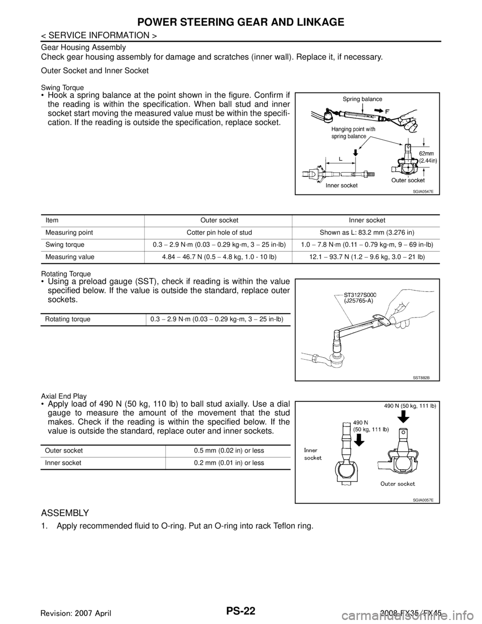
Swing Torque Hook a spring balance at the point shown in the figure. Confirm ifthe reading is within the specification. When ball stud and inner
socket start moving the measured value must be within the specifi-
cation. If the reading is outside the specification, replace socket.
Rotating Torque Using a preload gauge (SST), check if reading is within the valuespecified below. If the value is outside the standard, replace outer
sockets.
Axial End Play Apply load of 490 N (50 kg, 110 lb) to ball stud axially. Use a dialgauge to measure the amount of the movement that the stud
makes. Check if the reading is within the specified below. If the
value is outside the standard, replace outer and inner sockets.
ASSEMBLY
1. Apply recommended fluid to O-ring. Put an O-ring into rack Teflon ring.
SGIA0547E
Item Outer socket Inner socket
Measuring point Cotter pin hole of stud Shown as L: 83.2 mm (3.276 in)
Swing torque 0.3 − 2.9 N·m (0.03 − 0.29 kg-m, 3 − 25 in-lb) 1.0 − 7.8 N·m (0.11 − 0.79 kg-m, 9 − 69 in-lb)
Measuring value 4.84 − 46.7 N (0.5 − 4.8 kg, 1.0 - 10 lb) 12.1 − 93.7 N (1.2 − 9.6 kg, 3.0 − 21 lb)
Rotating torque 0.3 − 2.9 N·m (0.03 − 0.29 kg-m, 3 − 25 in-lb)
SST882B
Outer socket 0.5 mm (0.02 in) or less
Inner socket 0.2 mm (0.01 in) or less
SGIA0057E
3AA93ABC3ACD3AC03ACA3AC03AC63AC53A913A773A893A873A873A8E3A773A983AC73AC93AC03AC3
3A893A873A873A8F3A773A9D3AAF3A8A3A8C3A863A9D3AAF3A8B3A8C
Page 3479 of 3924
![INFINITI FX35 2008 Service Manual
PS-24
< SERVICE INFORMATION >
POWER STEERING GEAR AND LINKAGE
c. When installing outer rack oil seal, cover the end of rack with anOHP sheet [70 mm (2.76 in) × 100 mm (3.94 in)]. It will avoid
dama INFINITI FX35 2008 Service Manual
PS-24
< SERVICE INFORMATION >
POWER STEERING GEAR AND LINKAGE
c. When installing outer rack oil seal, cover the end of rack with anOHP sheet [70 mm (2.76 in) × 100 mm (3.94 in)]. It will avoid
dama](/manual-img/42/57017/w960_57017-3478.png)
PS-24
< SERVICE INFORMATION >
POWER STEERING GEAR AND LINKAGE
c. When installing outer rack oil seal, cover the end of rack with anOHP sheet [70 mm (2.76 in) × 100 mm (3.94 in)]. It will avoid
damaging rack oil seal. Then place oil seal on sheet. Pull rack oil
seal along with OHP sheet until they pass rack end. Then
remove OHP sheet.
d. Install end cover assembly to rack, move it to gear housing assembly.
5. Using a 45 mm (1.77 in) open head (suitable tool), tighten end cover assembly at the specified torque.
CAUTION:
Do not damage rack surface. If it is damaged, it may cause
oil leaks. Replace rack assembly.
6. After tightening end cover assembly, caulk cylinder at one point as shown in the figure using a punch. This will prevent end cover
from getting loose.
7. Install pinion assembly to gear housing assembly. CAUTION:
In order to protect oil seal from any damage, insert pinion
assembly out straightly.
8. Apply recommended fluid to O-ring. Install O-ring to rear cover.
9. Use a rear cover wrench (SST), install rear cover to gear hous- ing assembly.
10. Confirm projection on rear cover cap nearly fit with marking posi- tion on gear housing assembly.
11. Apply recommended thread locking sealant to the thread (2 turns thread), and then screw in the adjusting screw until it
reaches height “H” from gear housing assembly measured
before disassembling.
12. Rotate pinion ten times whole range of rack so that parts get to fit with each other.
SGIA0157E
SST081B
SGIA0158E
SGIA0568E
3AA93ABC3ACD3AC03ACA3AC03AC63AC53A913A773A893A873A873A8E3A773A983AC73AC93AC03AC3
3A893A873A873A8F3A773A9D3AAF3A8A3A8C3A863A9D3AAF3A8B3A8C
Page 3482 of 3924
POWER STEERING OIL PUMPPS-27
< SERVICE INFORMATION >
C
DE
F
H I
J
K L
M A
B
PS
N
O P
POWER STEERING OIL PUMP
On-Vehicle Inspection and ServiceINFOID:0000000001327718
CHECKING RELIEF OIL PRESSURE (VQ35DE MODELS)
CAUTION:
Before starting work, confirm belt tension is proper.
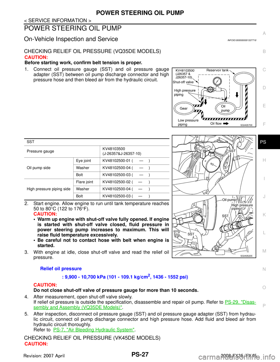
1. Connect oil pressure gauge (SST) and oil pressure gauge adapter (SST) between oil pump discharge connector and high
pressure hose and then bleed air from the hydraulic circuit.
2. Start engine. Allow engine to run until tank temperature reaches 50 to 80 °C (122 to 176 °F).
CAUTION:
Warm up engine with shut-o ff valve fully opened. If engine
is started with shut-off val ve closed, fluid pressure in
power steering pump increases to maximum. This will
raise fluid temperature excessively.
Be careful not to contact hose with belt when engine is
started.
3. With engine at idle, close shut-off valve and read the relief oil pressure.
CAUTION:
Do not close shut-off valve of pressu re gauge for more than 10 seconds.
4. After measurement, open shut-off valve slowly. If relief oil pressure is outside the specificat ion, disassemble and repair oil pump. Refer to PS-29, "
Disas-
sembly and Assembly (VQ35DE Models)".
5. After inspection, disconnect oil pressure gauge ( SST) and oil pressure gauge adapter (SST) from hydrau-
lic circuit, connect oil pump discharge connector and high pressure hose. Add fluid and bleed air from
hydraulic circuit thoroughly.
Refer to PS-7, "
Air Bleeding Hydraulic System".
CHECKING RELIEF OIL PRES SURE (VK45DE MODELS)
CAUTION:
SGIA0570E
SST
Pressure gauge KV48103500
(J-26357&J-26357-10)
Oil pump side Eye joint KV48102500-01 ( — )
Washer KV48102500-04 ( — )
Bolt KV48102500-03 ( — )
High pressure piping side Flare joint KV48102500-02 ( — )
Washer KV48102500-04 ( — )
Bolt KV48102500-03 ( — )
Relief oil pressure
: 9,900 - 10,700 kPa (101 - 109.1 kg/cm
2, 1436 - 1552 psi)
SGIA0522E
3AA93ABC3ACD3AC03ACA3AC03AC63AC53A913A773A893A873A873A8E3A773A983AC73AC93AC03AC3
3A893A873A873A8F3A773A9D3AAF3A8A3A8C3A863A9D3AAF3A8B3A8C
Page 3483 of 3924
PS-28
< SERVICE INFORMATION >
POWER STEERING OIL PUMP
Before starting work, confirm belt tension is proper.
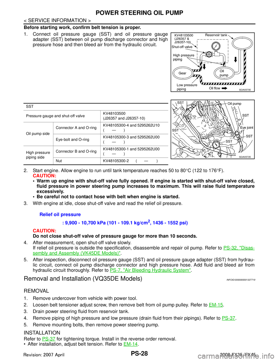
1. Connect oil pressure gauge (SST) and oil pressure gaugeadapter (SST) between oil pump discharge connector and high
pressure hose and then bleed air from the hydraulic circuit.
2. Start engine. Allow engine to run until tank temperature reaches 50 to 80 °C (122 to 176 °F).
CAUTION:
Warm up engine with shut-off val ve fully opened. If engine is started with shut-off valve closed,
fluid pressure in power steering pump increases to maximum. This will raise fluid temperature
excessively.
Be careful not to contact hose with belt when engine is started.
3. With engine at idle, close shut-off valve and read the relief oil pressure.
CAUTION:
Do not close shut-off valve of pressu re gauge for more than 10 seconds.
4. After measurement, open shut-off valve slowly. If relief oil pressure is outside the specification, disassemble and repair oil pump. Refer to PS-32, "
Disas-
sembly and Assembly (VK45DE Models)".
5. After inspection, disconnect oil pressure gauge (S ST) and oil pressure gauge adapter (SST) from hydrau-
lic circuit, connect oil pump discharge connector and high pressure hose. Add fluid and bleed air from
hydraulic circuit thoroughly. Refer to PS-7, "
Air Bleeding Hydraulic System".
Removal and Installation (VQ35DE Models)INFOID:0000000001327719
REMOVAL
1. Remove undercover from vehicle with power tool.
2. Loosen belt tensioner adjust screw, then remove belt from oil pump pulley. Refer to EM-15
.
3. Drain power steering fluid from reservoir tank.
4. Remove piping of high pressure and low pressure (drain fluid from their pipings). Refer to PS-37
.
5. Remove mounting bolts, then remove power steering pump.
INSTALLATION
Refer to PS-37 for tightening torque. Install in the reverse order removal.
After installation, adjust belt tension. Refer to EM-14
.
SGIA0570E
SST
Pressure gauge and shut-off valveKV48103500
(J26357 and J26357-10)
Oil pump side Connector A and O-ring
KV48105300-4 and 5295262U10
(—)
Eye-bolt and O-ring KV48105300-3 and 5295262U00
(—)
High pressure
piping side Connector B and O-ring
KV48105300-1 and 5295262U00
(—)
Nut KV48105300-2 ( — )
SGIA0572E
Relief oil pressure : 9,900 - 10,700 kPa (101 - 109.1 kg/cm
2, 1436 - 1552 psi)
3AA93ABC3ACD3AC03ACA3AC03AC63AC53A913A773A893A873A873A8E3A773A983AC73AC93AC03AC3
3A893A873A873A8F3A773A9D3AAF3A8A3A8C3A863A9D3AAF3A8B3A8C