2008 INFINITI FX35 flush
[x] Cancel search: flushPage 3344 of 3924
CHASSIS AND BODY MAINTENANCEMA-27
< SERVICE INFORMATION >
C
DE
F
G H
I
J
K
M A
B
MA
N
O P
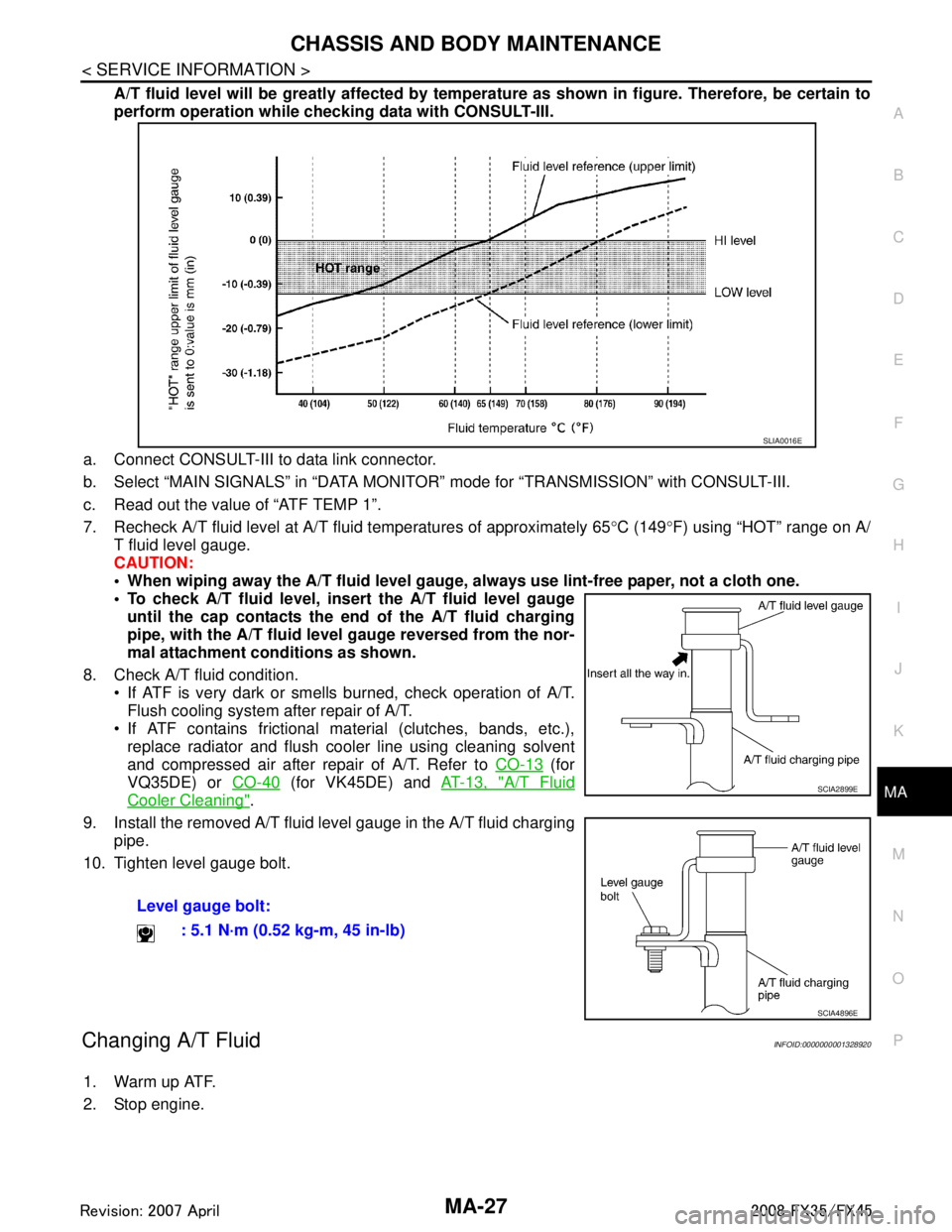
A/T fluid level will be greatly affected by temper ature as shown in figure. Therefore, be certain to
perform operation while checki ng data with CONSULT-III.
a. Connect CONSULT-III to data link connector.
b. Select “MAIN SIGNALS” in “DATA MONITOR” mode for “TRANSMISSION” with CONSULT-III.
c. Read out the value of “ATF TEMP 1”.
7. Recheck A/T fluid level at A/T fluid temperatures of approximately 65 °C (149 °F) using “HOT” range on A/
T fluid level gauge.
CAUTION:
When wiping away the A/T fluid level gauge, always use lint-free paper, not a cloth one.
To check A/T fluid level, inser t the A/T fluid level gauge
until the cap contacts the en d of the A/T fluid charging
pipe, with the A/T fluid level gauge reversed from the nor-
mal attachment conditions as shown.
8. Check A/T fluid condition. If ATF is very dark or smells burned, check operation of A/T.
Flush cooling system after repair of A/T.
If ATF contains frictional material (clutches, bands, etc.), replace radiator and flush cooler line using cleaning solvent
and compressed air after repair of A/T. Refer to CO-13
(for
VQ35DE) or CO-40
(for VK45DE) and AT-13, "A/T Fluid
Cooler Cleaning".
9. Install the removed A/T fluid level gauge in the A/T fluid charging pipe.
10. Tighten level gauge bolt.
Changing A/T FluidINFOID:0000000001328920
1. Warm up ATF.
2. Stop engine. Level gauge bolt:
: 5.1 N·m (0.52 kg-m, 45 in-lb)
SLIA0016E
SCIA2899E
SCIA4896E
3AA93ABC3ACD3AC03ACA3AC03AC63AC53A913A773A893A873A873A8E3A773A983AC73AC93AC03AC3
3A893A873A873A8F3A773A9D3AAF3A8A3A8C3A863A9D3AAF3A8B3A8C
Page 3544 of 3924
RFD-2
< SERVICE INFORMATION >
PRECAUTIONS
SERVICE INFORMATION
PRECAUTIONS
Service Notice or PrecautionINFOID:0000000001327490
• Check for the correct installation status prior to removal or disassembly. If matching marks are required, becertain they do not interfere with the function of the parts when applied.
Overhaul should be done in a clean work area, it is preferable to work in dustproof area.
Before disassembly, using steam or white gasoline, completely remove sand and mud from the exterior of
the unit, preventing them from entering into the unit during disassembly or assembly.
Check appearance of the disassembled parts for dam age, deformation, and unusual wear. Replace them
with a new ones if necessary.
Gaskets, seals and O-rings should be replaced any time when the unit is disassembled.
In principle, tighten bolts or nuts gradually in several steps working diagonally from inside to outside. If tight-
ening sequence is specified, observe it.
Clean and flush the parts sufficiently and blow-dry them.
Be careful not to damage sliding surfaces and mating surfaces.
When applying sealant, remove the old sealant from t he mounting surface; then remove any moisture, oil,
and foreign materials from the application and mounting surfaces.
Always use shop paper for cleaning the inside of components.
Avoid using cotton gloves or shop rags to prevent entering of lint.
During assembly, observe the specified tightening tor que, and apply new gear oil, petroleum jelly, or multi-
purpose grease as specified for each vehicle, if necessary.
3AA93ABC3ACD3AC03ACA3AC03AC63AC53A913A773A893A873A873A8E3A773A983AC73AC93AC03AC3
3A893A873A873A8F3A773A9D3AAF3A8A3A8C3A863A9D3AAF3A8B3A8C
Page 3557 of 3924
SIDE OIL SEALRFD-15
< SERVICE INFORMATION >
CEF
G H
I
J
K L
M A
B
RFD
N
O P
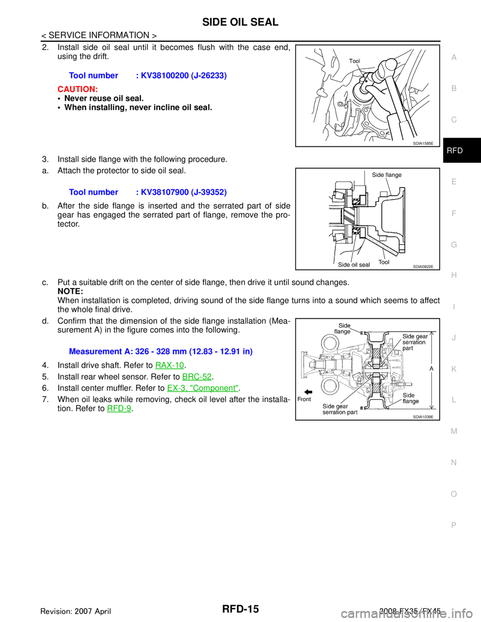
2. Install side oil seal until it becomes flush with the case end, using the drift.
CAUTION:
Never reuse oil seal.
When installing, never incline oil seal.
3. Install side flange with the following procedure.
a. Attach the protector to side oil seal.
b. After the side flange is inserted and the serrated part of side gear has engaged the serrated part of flange, remove the pro-
tector.
c. Put a suitable drift on the center of side flange, then drive it until sound changes.
NOTE:
When installation is completed, driving sound of the side flange turns into a sound which seems to affect
the whole final drive.
d. Confirm that the dimension of the side flange installation (Mea- surement A) in the figure comes into the following.
4. Install drive shaft. Refer to RAX-10
.
5. Install rear wheel sensor. Refer to BRC-52
.
6. Install center muffler. Refer to EX-3, "
Component".
7. When oil leaks while removing, check oil level after the installa- tion. Refer to RFD-9
.
Tool number : KV38100200 (J-26233)
SDIA1585E
Tool number : KV38107900 (J-39352)
SDIA0822E
Measurement A: 326 - 328 mm (12.83 - 12.91 in)
SDIA1039E
3AA93ABC3ACD3AC03ACA3AC03AC63AC53A913A773A893A873A873A8E3A773A983AC73AC93AC03AC3
3A893A873A873A8F3A773A9D3AAF3A8A3A8C3A863A9D3AAF3A8B3A8C
Page 3576 of 3924
RFD-34
< SERVICE INFORMATION >
REAR FINAL DRIVE ASSEMBLY
Differential Assembly
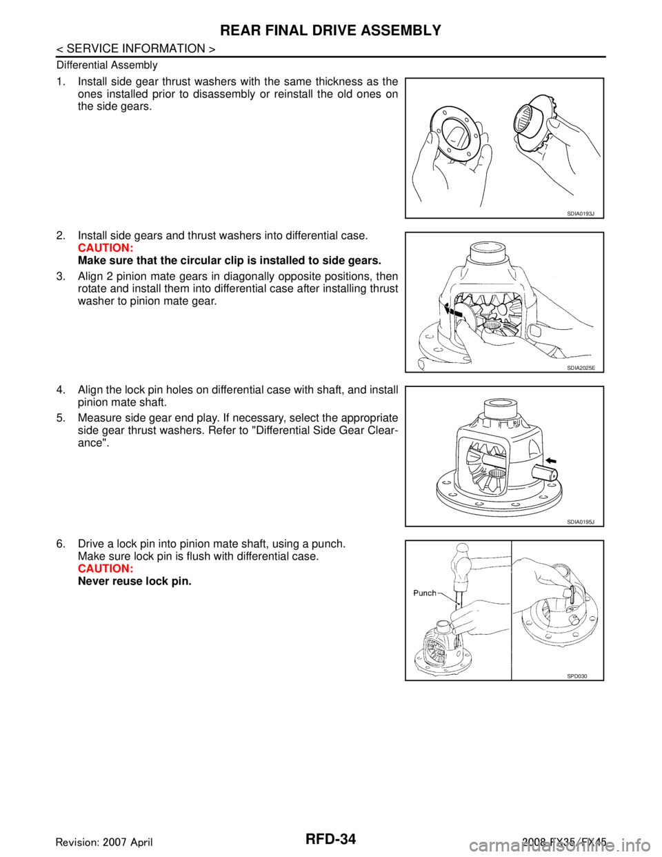
1. Install side gear thrust washers with the same thickness as theones installed prior to disassembly or reinstall the old ones on
the side gears.
2. Install side gears and thrust washers into differential case. CAUTION:
Make sure that the circular clip is installed to side gears.
3. Align 2 pinion mate gears in diagonally opposite positions, then rotate and install them into differential case after installing thrust
washer to pinion mate gear.
4. Align the lock pin holes on differential case with shaft, and install pinion mate shaft.
5. Measure side gear end play. If necessary, select the appropriate side gear thrust washers. Refer to "Differential Side Gear Clear-
ance".
6. Drive a lock pin into pinion mate shaft, using a punch. Make sure lock pin is flush with differential case.
CAUTION:
Never reuse lock pin.
SDIA0193J
SDIA2025E
SDIA0195J
SPD030
3AA93ABC3ACD3AC03ACA3AC03AC63AC53A913A773A893A873A873A8E3A773A983AC73AC93AC03AC3
3A893A873A873A8F3A773A9D3AAF3A8A3A8C3A863A9D3AAF3A8B3A8C
Page 3578 of 3924
RFD-36
< SERVICE INFORMATION >
REAR FINAL DRIVE ASSEMBLY
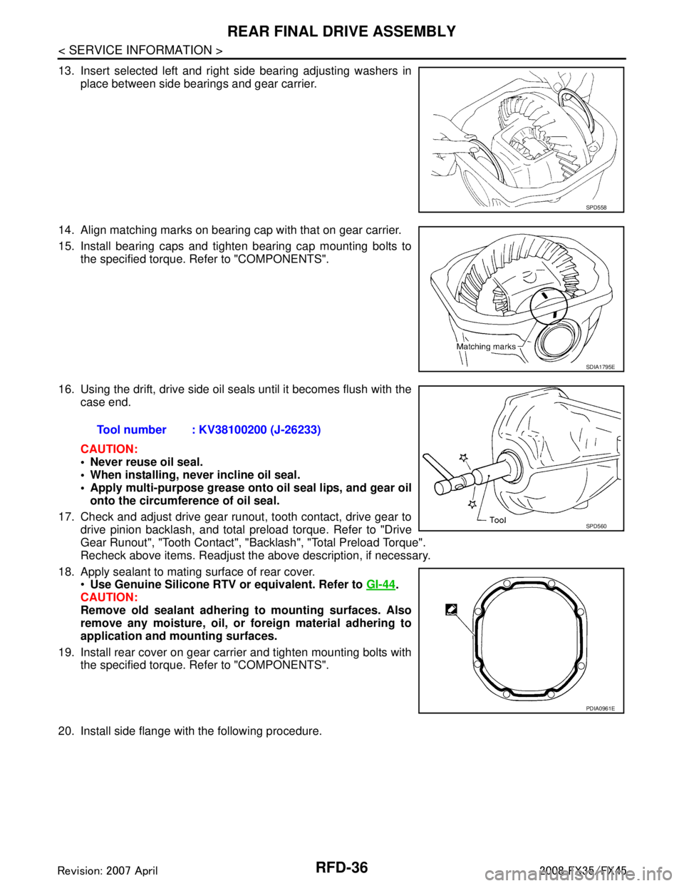
13. Insert selected left and right side bearing adjusting washers inplace between side bearings and gear carrier.
14. Align matching marks on bearing cap with that on gear carrier.
15. Install bearing caps and tighten bearing cap mounting bolts to the specified torque. Refer to "COMPONENTS".
16. Using the drift, drive side oil s eals until it becomes flush with the
case end.
CAUTION:
Never reuse oil seal.
When installing, n ever incline oil seal.
Apply multi-purpose grease onto oil seal lips, and gear oil
onto the circumference of oil seal.
17. Check and adjust drive gear runout, tooth contact, drive gear to drive pinion backlash, and total preload torque. Refer to "Drive
Gear Runout", "Tooth Contact", "Backlash", "Total Preload Torque".
Recheck above items. Readjust the above description, if necessary.
18. Apply sealant to mating surface of rear cover. Use Genuine Silicone RTV or equivalent. Refer to GI-44
.
CAUTION:
Remove old sealant adhering to mounting surfaces. Also
remove any moisture, oil, or foreign material adhering to
application and mounting surfaces.
19. Install rear cover on gear carrier and tighten mounting bolts with the specified torque. Refer to "COMPONENTS".
20. Install side flange with the following procedure.
SPD558
SDIA1795E
Tool number : KV38100200 (J-26233)
SPD560
PDIA0961E
3AA93ABC3ACD3AC03ACA3AC03AC63AC53A913A773A893A873A873A8E3A773A983AC73AC93AC03AC3
3A893A873A873A8F3A773A9D3AAF3A8A3A8C3A863A9D3AAF3A8B3A8C
Page 3613 of 3924
SC-4
< SERVICE INFORMATION >
BATTERY
BATTERY
How to Handle BatteryINFOID:0000000001328243
CAUTION:
If it becomes necessary to start the engine with a booster battery and jumper cables, use a 12-volt
booster battery.
After connecting battery cables, ensure that they are tightly clamped to battery terminals for good
contact.
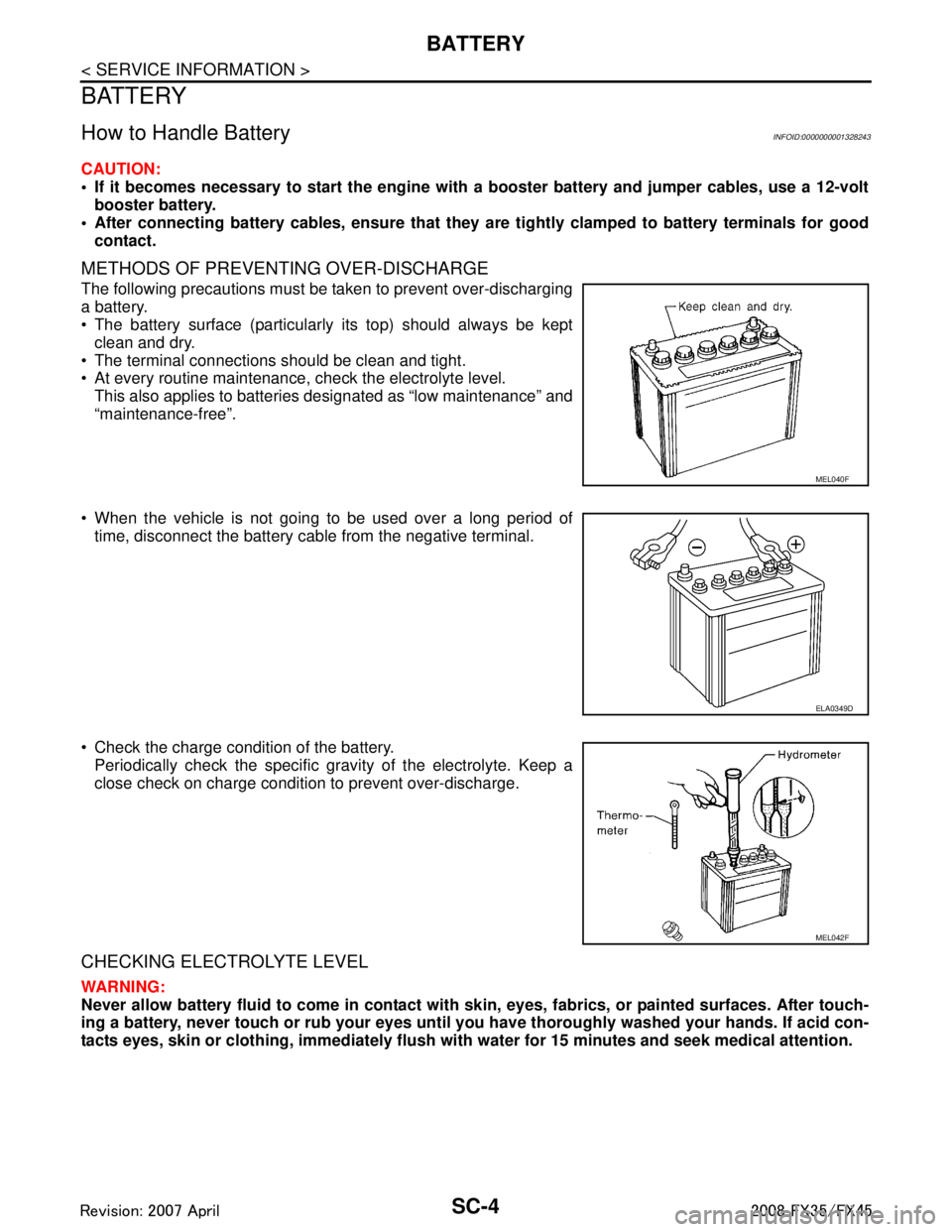
METHODS OF PREVENTING OVER-DISCHARGE
The following precautions must be taken to prevent over-discharging
a battery.
The battery surface (particularly its top) should always be kept clean and dry.
The terminal connections should be clean and tight.
At every routine maintenance, check the electrolyte level.
This also applies to batteries designated as “low maintenance” and
“maintenance-free”.
When the vehicle is not going to be used over a long period of time, disconnect the battery cable from the negative terminal.
Check the charge condition of the battery. Periodically check the specific gr avity of the electrolyte. Keep a
close check on charge condition to prevent over-discharge.
CHECKING ELECTROLYTE LEVEL
WARNING:
Never allow battery fluid to come in contact with skin, eyes, fabrics, or painted surfaces. After touch-
ing a battery, never touch or rub your eyes until you have thoroughly washed your hands. If acid con-
tacts eyes, skin or clothing, immediately flush wit h water for 15 minutes and seek medical attention.
MEL040F
ELA0349D
MEL042F
3AA93ABC3ACD3AC03ACA3AC03AC63AC53A913A773A893A873A873A8E3A773A983AC73AC93AC03AC3
3A893A873A873A8F3A773A9D3AAF3A8A3A8C3A863A9D3AAF3A8B3A8C
Page 3791 of 3924
PRECAUTIONSTF-5
< SERVICE INFORMATION >
CEF
G H
I
J
K L
M A
B
TF
N
O P
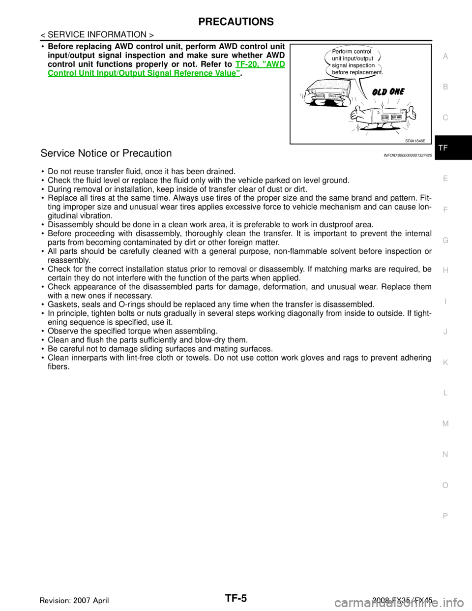
Before replacing AWD control unit, perform AWD control unit
input/output signal inspection and make sure whether AWD
control unit functions properly or not. Refer to TF-20, "
AW D
Control Unit Input/Output Signal Reference Value".
Service Notice or PrecautionINFOID:0000000001327425
Do not reuse transfer fluid, once it has been drained.
Check the fluid level or replace the fluid only with the vehicle parked on level ground.
During removal or installation, keep inside of transfer clear of dust or dirt.
Replace all tires at the same time. Always use tires of the proper size and the same brand and pattern. Fit-
ting improper size and unusual wear tires applies excessive force to vehicle mechanism and can cause lon-
gitudinal vibration.
Disassembly should be done in a clean work area, it is preferable to work in dustproof area.
Before proceeding with disassembly, thoroughly clean the tr ansfer. It is important to prevent the internal
parts from becoming contaminated by dirt or other foreign matter.
All parts should be carefully cleaned with a general purpose, non-flammable solvent before inspection or
reassembly.
Check for the correct installation status prior to remo val or disassembly. If matching marks are required, be
certain they do not interfere with t he function of the parts when applied.
Check appearance of the disassembled parts for dam age, deformation, and unusual wear. Replace them
with a new ones if necessary.
Gaskets, seals and O-rings should be replaced any time when the transfer is disassembled.
In principle, tighten bolts or nuts gradually in several steps working diagonally from inside to outside. If tight-
ening sequence is specified, use it.
Observe the specified torque when assembling.
Clean and flush the parts sufficiently and blow-dry them.
Be careful not to damage sliding surfaces and mating surfaces.
Clean innerparts with lint-free cloth or towels. Do not use cotton work gloves and rags to prevent adhering
fibers.
SDIA1848E
3AA93ABC3ACD3AC03ACA3AC03AC63AC53A913A773A893A873A873A8E3A773A983AC73AC93AC03AC3
3A893A873A873A8F3A773A9D3AAF3A8A3A8C3A863A9D3AAF3A8B3A8C
Page 3839 of 3924
TRANSFER ASSEMBLYTF-53
< SERVICE INFORMATION >
CEF
G H
I
J
K L
M A
B
TF
N
O P
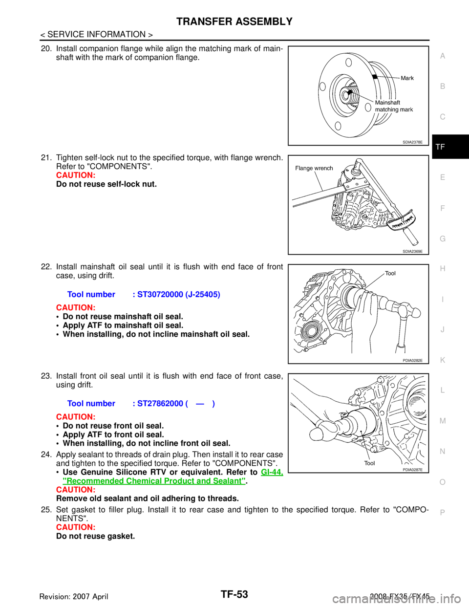
20. Install companion flange while align the matching mark of main- shaft with the mark of companion flange.
21. Tighten self-lock nut to the specified torque, with flange wrench. Refer to "COMPONENTS".
CAUTION:
Do not reuse self-lock nut.
22. Install mainshaft oil seal until it is flush with end face of front case, using drift.
CAUTION:
Do not reuse mainshaft oil seal.
Apply ATF to mainshaft oil seal.
When installing, do not in cline mainshaft oil seal.
23. Install front oil seal until it is flush with end face of front case, using drift.
CAUTION:
Do not reuse front oil seal.
Apply ATF to front oil seal.
When installing, do not incline front oil seal.
24. Apply sealant to threads of drain plug. Then install it to rear case and tighten to the specified torque. Refer to "COMPONENTS".
Use Genuine Silicone RTV or equivalent. Refer to GI-44,
"Recommended Chemical Product and Sealant".
CAUTION:
Remove old sealant and oil adhering to threads.
25. Set gasket to filler plug. Install it to rear case and tighten to the specified torque. Refer to "COMPO-
NENTS".
CAUTION:
Do not reuse gasket.
SDIA2378E
SDIA2369E
Tool number : ST30720000 (J-25405)
PDIA0282E
Tool number : ST27862000 ( — )
PDIA0287E
3AA93ABC3ACD3AC03ACA3AC03AC63AC53A913A773A893A873A873A8E3A773A983AC73AC93AC03AC3
3A893A873A873A8F3A773A9D3AAF3A8A3A8C3A863A9D3AAF3A8B3A8C