2008 INFINITI FX35 flush
[x] Cancel search: flushPage 2563 of 3924
![INFINITI FX35 2008 Service Manual
TIMING CHAINEM-79
< SERVICE INFORMATION > [VQ35DE]
C
D
E
F
G H
I
J
K L
M A
EM
NP
O
Install it so that each seal lip is oriented as shown in the figure.
Using a suitable drift [outer diameter: 60 INFINITI FX35 2008 Service Manual
TIMING CHAINEM-79
< SERVICE INFORMATION > [VQ35DE]
C
D
E
F
G H
I
J
K L
M A
EM
NP
O
Install it so that each seal lip is oriented as shown in the figure.
Using a suitable drift [outer diameter: 60](/manual-img/42/57017/w960_57017-2562.png)
TIMING CHAINEM-79
< SERVICE INFORMATION > [VQ35DE]
C
D
E
F
G H
I
J
K L
M A
EM
NP
O
Install it so that each seal lip is oriented as shown in the figure.
Using a suitable drift [outer diameter: 60 mm (2.36 in)], press-
fit oil seal until it becomes flush with front timing chain case
end face.
Make sure the garter spring is in position and seal lip is not
inverted.
13. Install water pump cover and chain tensioner cover to front timing chain case. Apply a continuous bead of liquid gasket with the tube presser
(commercial service tool) to front timing chain case as shown
in the figure.
Use Genuine RTV Silicone Seal ant or equivalent. Refer to
GI-44, "
Recommended Chemical Product and Sealant".
14. Install front timing chain case as follows:
SEM715A
PBIC0790E
SEM744GA
3AA93ABC3ACD3AC03ACA3AC03AC63AC53A913A773A893A873A873A8E3A773A983AC73AC93AC03AC3
3A893A873A873A8F3A773A9D3AAF3A8A3A8C3A863A9D3AAF3A8B3A8C
Page 2793 of 3924

FFD-2
< SERVICE INFORMATION >
PRECAUTIONS
SERVICE INFORMATION
PRECAUTIONS
Service Notice or PrecautionINFOID:0000000001327476
• Check for the correct installation status prior to removal or disassembly. If matching marks are required, becertain they do not interfere with the function of the parts when applied.
Overhaul should be done in a clean work area, it is preferable to work in dustproof area.
Before disassembly, using steam or white gasoline, completely remove sand and mud from the exterior of
the unit, preventing them from entering into the unit during disassembly or assembly.
Check appearance of the disassembled parts for dam age, deformation, and unusual wear. Replace them
with a new ones if necessary.
Gaskets, seals and O-rings should be replaced any time when the unit is disassembled.
In principle, tighten bolts or nuts gradually in several steps working diagonally from inside to outside. If tight-
ening sequence is specified, observe it.
Clean and flush the parts sufficiently and blow-dry them.
Be careful not to damage sliding surfaces and mating surfaces.
When applying sealant, remove the old sealant from t he mounting surface; then remove any moisture, oil,
and foreign materials from the application and mounting surfaces.
Always use shop paper for cleaning the inside of components.
Avoid using cotton gloves or shop rags to prevent entering of lint.
During assembly, observe the specified tightening tor que, and apply new gear oil, petroleum jelly, or multi-
purpose grease as specified for each vehicle, if necessary.
3AA93ABC3ACD3AC03ACA3AC03AC63AC53A913A773A893A873A873A8E3A773A983AC73AC93AC03AC3
3A893A873A873A8F3A773A9D3AAF3A8A3A8C3A863A9D3AAF3A8B3A8C
Page 2826 of 3924
FRONT FINAL DRIVE ASSEMBLYFFD-35
< SERVICE INFORMATION >
CEF
G H
I
J
K L
M A
B
FFD
N
O P
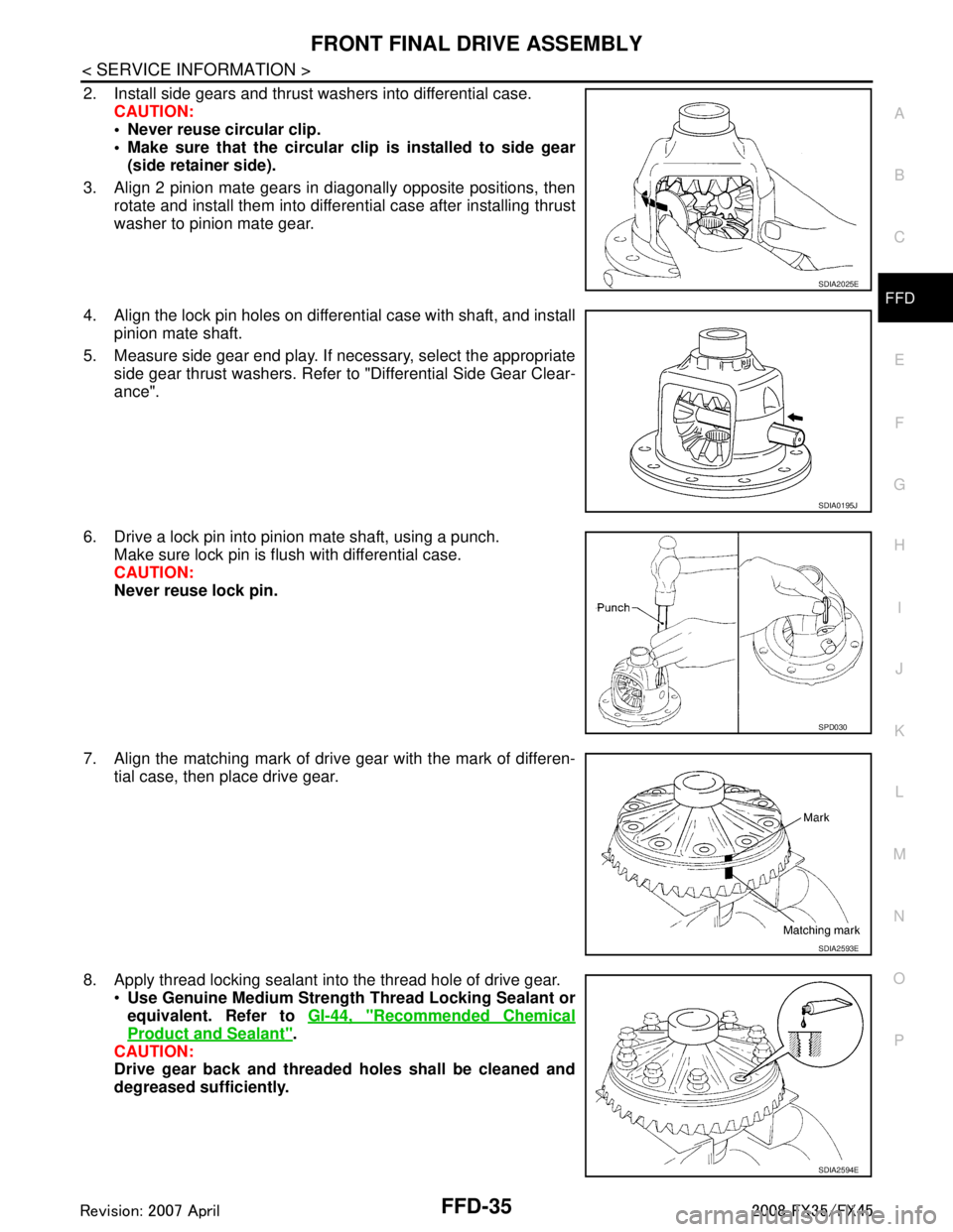
2. Install side gears and thrust washers into differential case. CAUTION:
Never reuse circular clip.
Make sure that the circular cl ip is installed to side gear
(side retainer side).
3. Align 2 pinion mate gears in diagonally opposite positions, then rotate and install them into differential case after installing thrust
washer to pinion mate gear.
4. Align the lock pin holes on differential case with shaft, and install pinion mate shaft.
5. Measure side gear end play. If necessary, select the appropriate side gear thrust washers. Refer to "Differential Side Gear Clear-
ance".
6. Drive a lock pin into pinion mate shaft, using a punch. Make sure lock pin is flush with differential case.
CAUTION:
Never reuse lock pin.
7. Align the matching mark of drive gear with the mark of differen- tial case, then place drive gear.
8. Apply thread locking sealant into the thread hole of drive gear. Use Genuine Medium Strength Thread Locking Sealant or
equivalent. Refer to GI-44, "
Recommended Chemical
Product and Sealant".
CAUTION:
Drive gear back and threaded holes shall be cleaned and
degreased sufficiently.
SDIA2025E
SDIA0195J
SPD030
SDIA2593E
SDIA2594E
3AA93ABC3ACD3AC03ACA3AC03AC63AC53A913A773A893A873A873A8E3A773A983AC73AC93AC03AC3
3A893A873A873A8F3A773A9D3AAF3A8A3A8C3A863A9D3AAF3A8B3A8C
Page 3321 of 3924
MA-4
< SERVICE INFORMATION >
GENERAL MAINTENANCE
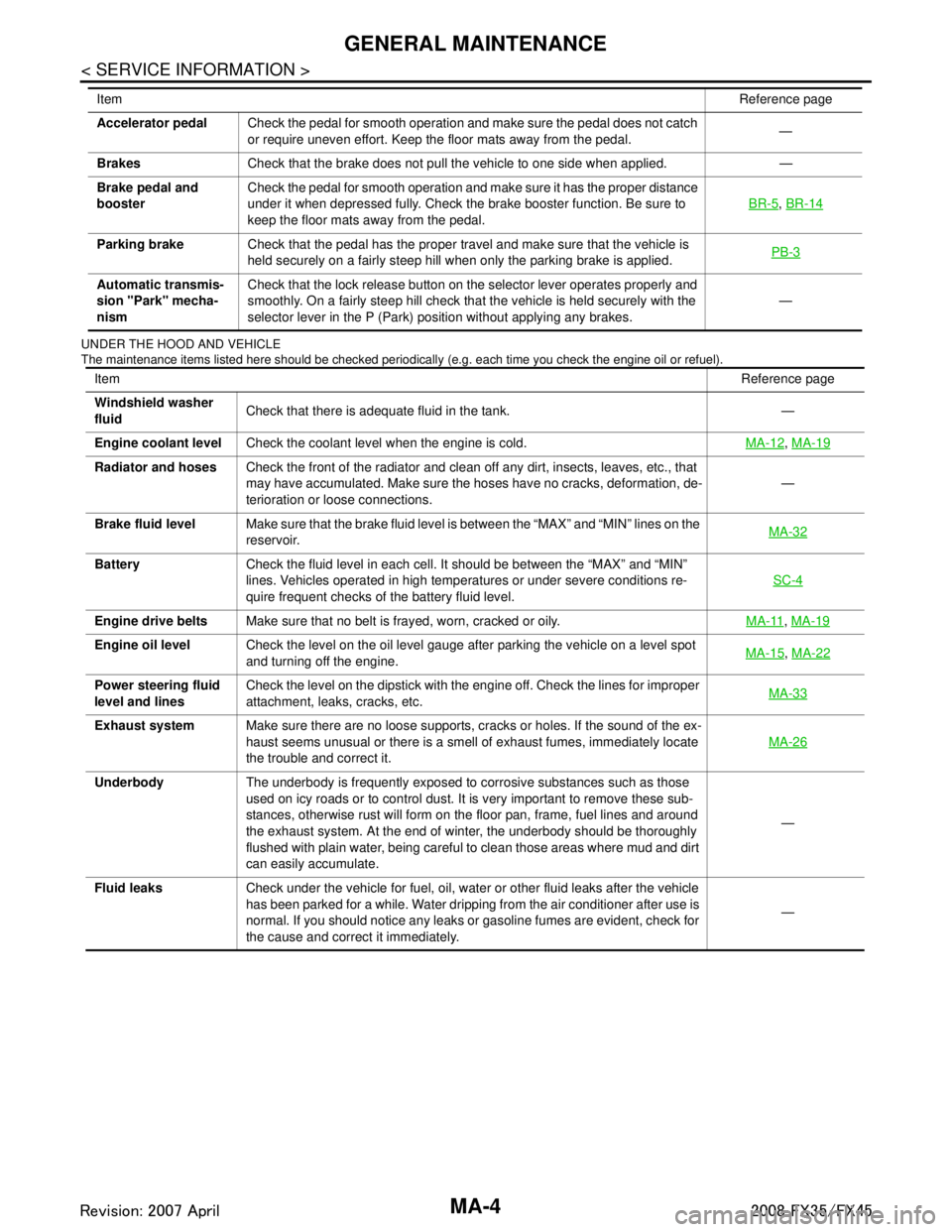
UNDER THE HOOD AND VEHICLE
The maintenance items listed here should be checked periodically (e.g. each time you check the engine oil or refuel).
Accelerator pedalCheck the pedal for smooth operation and make sure the pedal does not catch
or require uneven effort. Keep the floor mats away from the pedal. —
Brakes Check that the brake does not pull the vehicle to one side when applied. —
Brake pedal and
booster Check the pedal for smooth operation and make sure it has the proper distance
under it when depressed fully. Check the brake booster function. Be sure to
keep the floor mats away from the pedal. BR-5
,
BR-14
Parking brake Check that the pedal has the proper travel and make sure that the vehicle is
held securely on a fairly steep hill when only the parking brake is applied. PB-3
Automatic transmis-
sion "Park" mecha-
nismCheck that the lock release button on the selector lever operates properly and
smoothly. On a fairly steep hill check that the vehicle is held securely with the
selector lever in the P (Park) position without applying any brakes.
—
Item
Reference page
Item Reference page
Windshield washer
fluid Check that there is adequate fluid in the tank. —
Engine coolant level Check the coolant level when the engine is cold. MA-12
, MA-19
Radiator and hoses Check the front of the radiator and clean off any dirt, insects, leaves, etc., that
may have accumulated. Make sure the hoses have no cracks, deformation, de-
terioration or loose connections. —
Brake fluid level Make sure that the brake fluid level is between the “MAX” and “MIN” lines on the
reservoir. MA-32
Battery Check the fluid level in each cell. It should be between the “MAX” and “MIN”
lines. Vehicles operated in high temperatures or under severe conditions re-
quire frequent checks of the battery fluid level. SC-4
Engine drive belts
Make sure that no belt is frayed, worn, cracked or oily. MA-11, MA-19
Engine oil level Check the level on the oil level gauge after parking the vehicle on a level spot
and turning off the engine. MA-15,
MA-22
Power steering fluid
level and lines Check the level on the dipstick with the engine off. Check the lines for improper
attachment, leaks, cracks, etc.
MA-33
Exhaust system
Make sure there are no loose supports, cracks or holes. If the sound of the ex-
haust seems unusual or there is a smell of exhaust fumes, immediately locate
the trouble and correct it. MA-26
Underbody
The underbody is frequently exposed to corrosive substances such as those
used on icy roads or to control dust. It is very important to remove these sub-
stances, otherwise rust will form on the floor pan, frame, fuel lines and around
the exhaust system. At the end of winter, the underbody should be thoroughly
flushed with plain water, being careful to clean those areas where mud and dirt
can easily accumulate. —
Fluid leaks Check under the vehicle for fuel, oil, water or other fluid leaks after the vehicle
has been parked for a while. Water dripping from the air conditioner after use is
normal. If you should notice any leaks or gasoline fumes are evident, check for
the cause and correct it immediately. —
3AA93ABC3ACD3AC03ACA3AC03AC63AC53A913A773A893A873A873A8E3A773A983AC73AC93AC03AC3
3A893A873A873A8F3A773A9D3AAF3A8A3A8C3A863A9D3AAF3A8B3A8C
Page 3330 of 3924
ENGINE MAINTENANCE (VQ35DE ENGINE)MA-13
< SERVICE INFORMATION >
C
DE
F
G H
I
J
K
M A
B
MA
N
O P
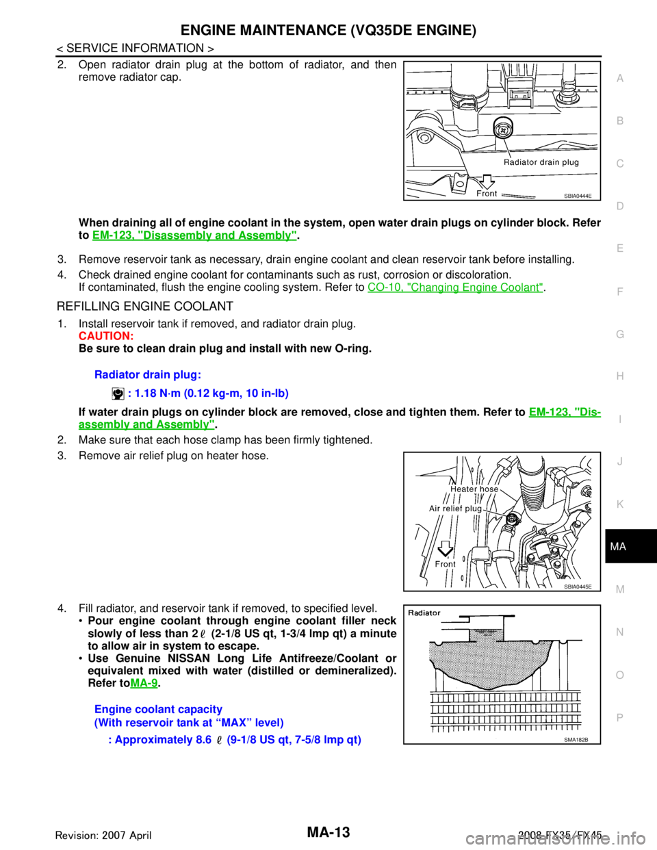
2. Open radiator drain plug at the bottom of radiator, and then
remove radiator cap.
When draining all of engine coolant in the system , open water drain plugs on cylinder block. Refer
to EM-123, "
Disassembly and Assembly".
3. Remove reservoir tank as necessary, drain engine coolant and clean reservoir tank before installing.
4. Check drained engine coolant for contaminants such as rust, corrosion or discoloration. If contaminated, flush the engine cooling system. Refer to CO-10, "
Changing Engine Coolant".
REFILLING ENGINE COOLANT
1. Install reservoir tank if removed, and radiator drain plug.
CAUTION:
Be sure to clean drain plug and install with new O-ring.
If water drain plugs on cylinder block are removed, close and tighten them. Refer to EM-123, "
Dis-
assembly and Assembly".
2. Make sure that each hose clamp has been firmly tightened.
3. Remove air relief plug on heater hose.
4. Fill radiator, and reservoir tank if removed, to specified level. Pour engine coolant through engine coolant filler neck
slowly of less than 2 (2-1/8 US qt, 1-3/4 lmp qt) a minute
to allow air in system to escape.
Use Genuine NISSAN Long Li fe Antifreeze/Coolant or
equivalent mixed with water (dis tilled or demineralized).
Refer to MA-9
.
SBIA0444E
Radiator drain plug:
: 1.18 N·m (0.12 kg-m, 10 in-lb)
SBIA0445E
Engine coolant capacity
(With reservoir tank at “MAX” level): Approximately 8.6 (9-1/8 US qt, 7-5/8 lmp qt)
SMA182B
3AA93ABC3ACD3AC03ACA3AC03AC63AC53A913A773A893A873A873A8E3A773A983AC73AC93AC03AC3
3A893A873A873A8F3A773A9D3AAF3A8A3A8C3A863A9D3AAF3A8B3A8C
Page 3331 of 3924
MA-14
< SERVICE INFORMATION >
ENGINE MAINTENANCE (VQ35DE ENGINE)
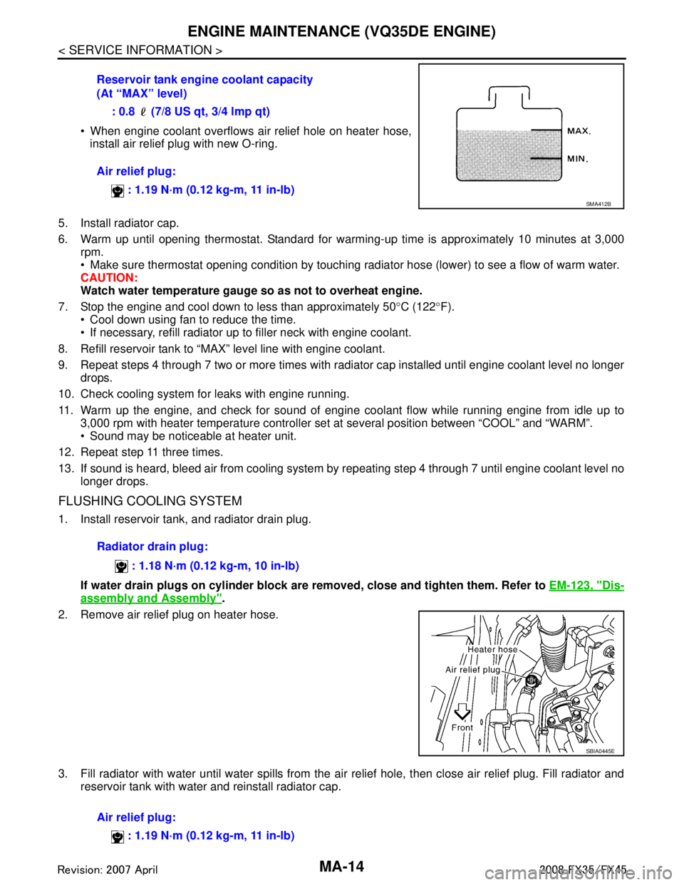
When engine coolant overflows air relief hole on heater hose,install air relief plug with new O-ring.
5. Install radiator cap.
6. Warm up until opening thermostat. Standard for warming- up time is approximately 10 minutes at 3,000
rpm.
Make sure thermostat opening condition by touching radiator hose (lower) to see a flow of warm water.
CAUTION:
Watch water temperature gauge so as not to overheat engine.
7. Stop the engine and cool down to less than approximately 50 °C (122 °F).
Cool down using fan to reduce the time.
If necessary, refill radiator up to filler neck with engine coolant.
8. Refill reservoir tank to “MAX” level line with engine coolant.
9. Repeat steps 4 through 7 two or more times with radiator cap installed until engine coolant level no longer drops.
10. Check cooling system for leaks with engine running.
11. Warm up the engine, and check for sound of engine coolant flow while running engine from idle up to 3,000 rpm with heater temperature controller set at several position between “COOL” and “WARM”.
Sound may be noticeable at heater unit.
12. Repeat step 11 three times.
13. If sound is heard, bleed air from cooling system by repeating step 4 through 7 until engine coolant level no
longer drops.
FLUSHING COOLING SYSTEM
1. Install reservoir tank, and radiator drain plug.
If water drain plugs on cylinder block are removed, close and tighten them. Refer to EM-123, "
Dis-
assembly and Assembly".
2. Remove air relief plug on heater hose.
3. Fill radiator with water until water spills from the ai r relief hole, then close air relief plug. Fill radiator and
reservoir tank with water and reinstall radiator cap. Reservoir tank engine coolant capacity
(At “MAX” level)
: 0.8 (7/8 US qt, 3/4 lmp qt)
Air relief plug: : 1.19 N·m (0.12 kg-m, 11 in-lb)
SMA412B
Radiator drain plug:
: 1.18 N·m (0.12 kg-m, 10 in-lb)
SBIA0445E
Air relief plug: : 1.19 N·m (0.12 kg-m, 11 in-lb)
3AA93ABC3ACD3AC03ACA3AC03AC63AC53A913A773A893A873A873A8E3A773A983AC73AC93AC03AC3
3A893A873A873A8F3A773A9D3AAF3A8A3A8C3A863A9D3AAF3A8B3A8C
Page 3337 of 3924

MA-20
< SERVICE INFORMATION >
ENGINE MAINTENANCE (VK45DE ENGINE)
2. Open radiator drain plug at the bottom of radiator, and thenremove radiator cap.
When draining all of engine cool ant in the system, open water drai n plugs on cylinder block. Refer
to EM-242, "
Disassembly and Assembly".
3. Remove reservoir tank as necessary, and drain engine coolant and clean reservoir tank before installing.
4. Check drained engine coolant for contaminants such as rust, corrosion or discoloration. If contaminated, flush the engine cooling system. Refer to "FLUSHING COOLING SYSTEM".
REFILLING ENGINE COOLANT
1. Install reservoir tank, and radiator drain plug.
CAUTION:
Be sure to clean radiator drain plug and install with new O-ring.
If water drain plugs on cylinder block are removed, close and tighten them. Refer to EM-242, "
Dis-
assembly and Assembly".
2. Make sure that each hose clamp has been firmly tightened.
3. Remove air relief plug on heater hose.
4. Fill thermostat housing and reservoir tank to specified level. Refill engine coolant up to fill er neck of thermostat housing.
Pour engine coolant through engine coolant filler neck slowly of less than 2 (2-1/8 US qt, 1-3/4
Imp qt) a minute to allo w air in system to escape.
Use Genuine NISSAN long Life Antifreeze/Coolant or equivalent mixed with water (distilled or
demineralized). Refer to MA-9
.
SBIA0444E
Radiator drain plug:
: 1.19 N·m (0.12 kg-m, 11 in-lb)
PBIC1530E
Engine coolant capacity
(With reservoir tank at “MAX” level):Approx. 10.0 (10-5/8 US qt, 8-3/4 Imp qt)
3AA93ABC3ACD3AC03ACA3AC03AC63AC53A913A773A893A873A873A8E3A773A983AC73AC93AC03AC3
3A893A873A873A8F3A773A9D3AAF3A8A3A8C3A863A9D3AAF3A8B3A8C
Page 3338 of 3924
ENGINE MAINTENANCE (VK45DE ENGINE)MA-21
< SERVICE INFORMATION >
C
DE
F
G H
I
J
K
M A
B
MA
N
O P
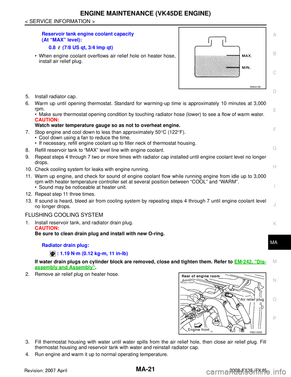
When engine coolant overflows air relief hole on heater hose, install air relief plug.
5. Install radiator cap.
6. Warm up until opening thermostat. Standard for warm ing-up time is approximately 10 minutes at 3,000
rpm.
Make sure thermostat opening condition by touching r adiator hose (lower) to see a flow of warm water.
CAUTION:
Watch water temperature gauge so as not to overheat engine.
7. Stop engine and cool down to less than approximately 50 °C (122 °F).
Cool down using a fan to reduce the time.
If necessary, refill engine coolant up to filler neck of thermostat housing.
8. Refill reservoir tank to “MAX” level line with engine coolant.
9. Repeat steps 4 through 7 two or more times with radiator cap installed until engine coolant level no longer drops.
10. Check cooling system for leaks with engine running.
11. Warm up engine, and check for sound of engine coolant flow while running engine from idle up to 3,000 rpm with heater temperature controller set at several position between “COOL” and “WARM”.
Sound may be noticeable at heater unit.
12. Repeat step 11 three times.
13. If sound is heard, bleed air from cooling system by repeating steps 4 through 7 until engine coolant level
no longer drops.
FLUSHING COOLING SYSTEM
1. Install reservoir tank, and radiator drain plug. CAUTION:
Be sure to clean drain plug and install with new O-ring.
If water drain plugs on cylinder block are removed, close and tighten them. Refer to EM-242, "
Dis-
assembly and Assembly".
2. Remove air relief plug on heater hose.
3. Fill thermostat housing with water until water spills from the air relief hole, then close air relief plug. Fill
thermostat housing and reservoir tank with water and reinstall radiator cap.
4. Run engine and warm it up to normal operating temperature. Reservoir tank engine coolant capacity
(At “MAX” level):
0.8 (7/8 US qt, 3/4 lmp qt)
SMA412B
Radiator drain plug:
: 1.19 N·m (0.12 kg-m, 11 in-lb)
PBIC1530E
3AA93ABC3ACD3AC03ACA3AC03AC63AC53A913A773A893A873A873A8E3A773A983AC73AC93AC03AC3
3A893A873A873A8F3A773A9D3AAF3A8A3A8C3A863A9D3AAF3A8B3A8C