2008 INFINITI FX35 warning light
[x] Cancel search: warning lightPage 1047 of 3924
![INFINITI FX35 2008 Service Manual
BRC-32
< SERVICE INFORMATION >[VDC/TCS/ABS]
TROUBLE DIAGNOSIS
Basic Inspection
INFOID:0000000001327676
BRAKE FLUID AMOUNT, LEAKS, AND BRAKE PADS INSPECTION
1. Check fluid level in the brake reservoir INFINITI FX35 2008 Service Manual
BRC-32
< SERVICE INFORMATION >[VDC/TCS/ABS]
TROUBLE DIAGNOSIS
Basic Inspection
INFOID:0000000001327676
BRAKE FLUID AMOUNT, LEAKS, AND BRAKE PADS INSPECTION
1. Check fluid level in the brake reservoir](/manual-img/42/57017/w960_57017-1046.png)
BRC-32
< SERVICE INFORMATION >[VDC/TCS/ABS]
TROUBLE DIAGNOSIS
Basic Inspection
INFOID:0000000001327676
BRAKE FLUID AMOUNT, LEAKS, AND BRAKE PADS INSPECTION
1. Check fluid level in the brake reservoir tank. If fluid level is low, refill brake fluid.
2. Check brake piping and around ABS actuator and electric uni t (control unit) for leaks. If there is leaking or
oozing fluid, check the following items.
If ABS actuator and electric unit (control unit) connec tion is loose, tighten piping to the specified torque
and re-perform the leak inspection to make sure there are no leaks.
If there is damage to the connection flare nut or AB S actuator and electric unit (control unit) screw,
replace the damaged part and re-perform the leak inspection to make sure there are no leaks.
When there is fluid leaking or oozing from a part other than ABS actuator and electric unit (control unit)
connection, if fluid is just oozing out, use a clean cl oth to wipe off the oozing fluid and re-check for leaks.
If fluid is still oozing out, replace the damaged part.
When there is fluid leaking or oozing at ABS actuator and electric unit (control unit), if fluid is just oozing
out, use a clean cloth to wipe off oozing fluid and re-che ck for leaks. If fluid is still oozing out, replace
ABS actuator and electric unit (control unit) body.
CAUTION:
ABS actuator and electric unit (contr ol unit) body can not be disassembled.
3. Check brake pad degree of wear. Refer to BR-18, "
On-Vehicle Inspection" in “Front Disc Brake” and BR-
24, "On-Vehicle Inspection" in “Rear Disc Brake”
POWER SYSTEM TERMINAL LOOSENESS AND BATTERY INSPECTION
Make sure battery positive cable, negative cabl e and ground connection are not loose. If looseness is
detected, tighten the cables. In additi on, check the battery voltage to make sure it has not dropped and alter-
nator is normal.
ABS WARNING LAMP, VDC OFF INDICATOR LAMP, SLIP INDICATOR LAMP AND BRAKE WARN-
ING LAMP INSPECTION
Symptom Symptom description Result
Motor operation noise This is noise of motor in
side ABS actuator and electr ic unit (control unit).
Slight noise may occur during VDC, TCS, and ABS operation.
Normal
When the vehicle speed goes over 20 km/h (12.5 MPH), motor and valves
operating noise may be heard. It happens only once after ignition switch is
ON. This is a normal status of the system operation check.
System operation check noise When engine starts, slight “click” noise may be heard from engine room.
This is normal and is part of system operation check. Normal
VDC/TCS operation
(SLIP indicator lamp blinking) TCS may activate momentarily if wheel speed changes when driving over
location where friction coefficient varies, when up/downshifting, or when ful-
ly depressing accelerator pedal.
Normal
Cancel the VDC/TCS
function for the inspec-
tion on a chassis dyna-
mometer.
For inspection of speedometer or other instruments, press VDC OFF switch
to turn VDC/TCS function off.
When accelerator pedal is depressed on a chassis dynamometer (fixed
front-wheel type), vehicle speed will not increase. This is not normal. It is re-
sult of TCS being activated by stationary front wheels. Warning lamp may
also illuminate to indicate “sensor system error”. This is also normal, and is
the result of the stationary front wheels being detected. To be certain, restart
engine, and drive vehicle at 30 km/h (19 MPH) or more. Make sure warning
lamp does not illuminate.
ABS operation
(Longer stopping distance) On roads with low friction coefficients, such as snowy roads or gravel roads,
vehicles with ABS may require a longer stopping distance. Therefore, when
driving on such roads, avoid overconfidence and keep speed sufficiently
low.
Normal
Insufficient feeling of accelera-
tion Depending on road conditions, driver may feel that feeling of acceleration is
insufficient. This is because traction control, which controls engine and
brakes to achieve optimal traction, has the highest priority (for safety). As a
result, there may be times when acceleration is slightly less than usual for
the same accelerator pedal operation.
Normal
3AA93ABC3ACD3AC03ACA3AC03AC63AC53A913A773A893A873A873A8E3A773A983AC73AC93AC03AC3
3A893A873A873A8F3A773A9D3AAF3A8A3A8C3A863A9D3AAF3A8B3A8C
Page 1065 of 3924
![INFINITI FX35 2008 Service Manual
BRC-50
< SERVICE INFORMATION >[VDC/TCS/ABS]
TROUBLE DIAGNOSIS FOR SYMPTOMS
The ABS Function Does Not Operate
INFOID:0000000001327695
CAUTION:
The ABS does not operate when the sp eed is 10 km/h (6 M INFINITI FX35 2008 Service Manual
BRC-50
< SERVICE INFORMATION >[VDC/TCS/ABS]
TROUBLE DIAGNOSIS FOR SYMPTOMS
The ABS Function Does Not Operate
INFOID:0000000001327695
CAUTION:
The ABS does not operate when the sp eed is 10 km/h (6 M](/manual-img/42/57017/w960_57017-1064.png)
BRC-50
< SERVICE INFORMATION >[VDC/TCS/ABS]
TROUBLE DIAGNOSIS FOR SYMPTOMS
The ABS Function Does Not Operate
INFOID:0000000001327695
CAUTION:
The ABS does not operate when the sp eed is 10 km/h (6 MPH) or less.
1.CHECK ABS WARNING LAMP DISPLAY
Make sure warning lamp turns off approximately 2 seconds after the ignition switch is turned ON or when driv-
ing.
OK or NG
OK >> CHECK WHEEL SENSOR. Refer to BRC-49, "Excessive ABS Function Operation Frequency".
NG >> Perform self-diagnosis. Refer to BRC-26, "
Self-Diagnosis".
Pedal Vibration or ABS Operation Sound OccursINFOID:0000000001327696
CAUTION:
Under the following conditions, when brake pedal is lightly depressed (just place a foot on it), ABS is
activated and vibration is felt. However, this is normal.
When shifting gears
When driving on slippery road
During cornering at high speed
When passing over bumps or grooves
When pulling away just after st arting engine [at approximately 10 km/h (6 MPH) or higher]
1.SYMPTOM CHECK 1
Check if pedal vibration or operati on sound occurs when engine is started.
OK or NG
OK >> Perform self-diagnosis. Refer to BRC-26, "Self-Diagnosis".
NG >> GO TO 2.
2.SYMPTOM CHECK 2
Check symptom when electrical component (headlamps, etc.) switches are operated.
Does the symptom occur when the electrical component (head lamp, etc.) switches are operated?
YES >> Check if there is a radio, antenna, antenna lead wi re, or wiring close to ABS actuator and electric
unit (control unit) (or its wiring), and if there is, move it farther away.
NO >> CHECK WHEEL SENSOR. Refer to BRC-49, "
Excessive ABS Function Operation Frequency".
Vehicle Jerks During VDC/TCS/ABS ControlINFOID:0000000001327697
1.CHECK ENGINE SPEED SIGNAL
Perform CONSULT-III “DATA MONITOR” to check engine speed.
Is engine speed at idle 400 rpm or higher?
YES >> GO TO 3.
NO >> GO TO 2.
2.CHECK ABS WARNING LAMP DISPLAY
Make sure warning lamp turns off approximately 2 seconds after the ignition switch is turned ON or when driv-
ing.
OK or NG
OK >> System is normal.
NG >> GO TO 3.
3.CHECK ECM SELF-DIAGNOSTIC RESULTS
Perform ECM self-diagnosis.
Are self-diagnosis items displayed?
YES >> Check the corresponding items. Refer to EC-89(VQ35DE), EC-666(VK45DE) in “Engine Control
(EC section)”.
NO >> GO TO 4.
3AA93ABC3ACD3AC03ACA3AC03AC63AC53A913A773A893A873A873A8E3A773A983AC73AC93AC03AC3
3A893A873A873A8F3A773A9D3AAF3A8A3A8C3A863A9D3AAF3A8B3A8C
Page 1074 of 3924
![INFINITI FX35 2008 Service Manual
PRECAUTIONSCO-3
< SERVICE INFORMATION > [VQ35DE]
C
D
E
F
G H
I
J
K L
M A
CO
NP
O
SERVICE INFORMATION
PRECAUTIONS
Precaution for Supplemental
Restraint System (SRS) "AIR BAG" and "SEAT BELT
PRE-TENS INFINITI FX35 2008 Service Manual
PRECAUTIONSCO-3
< SERVICE INFORMATION > [VQ35DE]
C
D
E
F
G H
I
J
K L
M A
CO
NP
O
SERVICE INFORMATION
PRECAUTIONS
Precaution for Supplemental
Restraint System (SRS) "AIR BAG" and "SEAT BELT
PRE-TENS](/manual-img/42/57017/w960_57017-1073.png)
PRECAUTIONSCO-3
< SERVICE INFORMATION > [VQ35DE]
C
D
E
F
G H
I
J
K L
M A
CO
NP
O
SERVICE INFORMATION
PRECAUTIONS
Precaution for Supplemental
Restraint System (SRS) "AIR BAG" and "SEAT BELT
PRE-TENSIONER"
INFOID:0000000001612910
The Supplemental Restraint System such as “A IR BAG” and “SEAT BELT PRE-TENSIONER”, used along
with a front seat belt, helps to reduce the risk or severi ty of injury to the driver and front passenger for certain
types of collision. This system includes seat belt switch inputs and dual stage front air bag modules. The SRS
system uses the seat belt switches to determine the front air bag deployment, and may only deploy one front
air bag, depending on the severity of a collision and whether the front occupants are belted or unbelted.
Information necessary to service the system safely is included in the “SUPPLEMENTAL RESTRAINT SYS-
TEM” and “SEAT BELTS” of this Service Manual.
WARNING:
• To avoid rendering the SRS inoper ative, which could increase the risk of personal injury or death in
the event of a collision which would result in air bag inflation, all maintenance must be performed by
an authorized NISSAN/INFINITI dealer.
Improper maintenance, including in correct removal and installation of the SRS, can lead to personal
injury caused by unintentional act ivation of the system. For removal of Spiral Cable and Air Bag
Module, see the “SUPPLEMEN TAL RESTRAINT SYSTEM”.
Do not use electrical test equipm ent on any circuit related to the SRS unless instructed to in this
Service Manual. SRS wiring harnesses can be identi fied by yellow and/or orange harnesses or har-
ness connectors.
Precaution for Liquid GasketINFOID:0000000001325839
REMOVAL OF LIQUID GASKET SEALING
After removing mounting nuts and bolts, separate the mating sur- face using the seal cutter (SST) and remove old liquid gasket seal-
ing.
CAUTION:
Be careful not to damage the mating surfaces.
Tap the seal cutter to insert it, and then slide it by tapping on the
side as shown in the figure.
In areas where seal cutter is difficult to use, use a plastic hammer to lightly tap the parts, to remove it.
CAUTION:
If for some unavoidable reason tool such as a screwdriver is
used, be careful not to damage the mating surfaces.
LIQUID GASKET APPLICATION PROCEDURE
1. Using a scraper, remove old liquid gasket adhering to the liquid gasket application surface and the mating surface.
Remove liquid gasket completely from the groove of the liquid
gasket application surface, mounting bolts, and bolt holes.
2. Wipe the liquid gasket application surface and the mating sur- face with white gasoline (lighting and heating use) to remove
adhering moisture, grease and foreign materials.
PBIC0002E
PBIC0003E
3AA93ABC3ACD3AC03ACA3AC03AC63AC53A913A773A893A873A873A8E3A773A983AC73AC93AC03AC3
3A893A873A873A8F3A773A9D3AAF3A8A3A8C3A863A9D3AAF3A8B3A8C
Page 1128 of 3924

DI-2
CONSULT-III Function (BCM) ................................60
Trouble Diagnosis ...................................................61
Symptom Chart .......................................................61
Power Supply and Ground Circuit Inspection .........61
Combination Meter Buzzer Circuit Inspection .........62
Front Door Switch (Driver Side) Signal Inspection ...63
Key Switch Signal Inspection (Without Intelligent
Key) ..................................................................... ...
64
Key Switch and Ignition Knob Switch Signal In-
spection (With Intelligent Key, When Mechanical
Key Is Used) ........................................................ ...
65
Lighting Switch Signal Inspection ...........................66
Seat Belt Buckle Switch (Driver Side) Signal In-
spection ............................................................... ...
66
Component Inspection ............................................67
LANE DEPARTURE WARNING SYSTEM ........69
Precaution for Lane Departure Warning (LDW)
system ................................................................. ...
69
System Description .................................................69
Action Test ..............................................................71
Camera Aiming Adjustment ....................................71
Component Parts and Harness Connector Loca-
tion ..........................................................................
76
Schematic ...............................................................77
Wiring Diagram - LDW - .........................................78
Terminal and Reference Value for LDW Camera
Unit .........................................................................
81
CONSULT-III Function (LDW) ................................81
Trouble Diagnosis ...................................................83
Preliminary Check ..................................................84
Power Supply and Ground Circuit Inspection .........84
DTC [C1B00] CAMERA UNIT MALF ......................85
DTC [C1B01] CAM AIMING INCMP .......................85
DTC [C1B02] VHCL SPD DATA MALF ..................85
DTC [C1B03] ABNRML TEMP DETECT ................86
DTC [U1000] CAN COMM CIRCUIT ......................86
DTC [U1010] CONTROL UNIT (CAN) ....................86
LDW Chime Circuit Inspection ................................86
LDW Switch Circuit Inspection ...............................88
LDW Indicator Lamp Circuit Inspection ..................90
Turn Signal Input Inspection ................................ ...91
Electrical Component Inspection ............................91
Removal and Installation for LDW Camera Unit .....91
Removal and Installation for LDW Chime ............ ...91
Removal and Installation for LDW Switch ...............92
CAN COMMUNICATION ...................................93
System Description .............................................. ...93
CAN Communication Unit .......................................93
COMPASS .........................................................94
Precaution for Compass ...................................... ...94
System Description .................................................94
Troubleshooting ......................................................94
Zone Variation Setting Procedure ...........................95
Calibration Procedure .............................................95
Wiring Diagram - COMPAS - ..................................97
Removal and Installation of Compass ....................97
CLOCK ..............................................................98
Wiring Diagram - CLOCK - .................................. ...98
Removal and Installation of Clock ...........................98
REAR VIEW MONITOR ....................................100
System Description .............................................. .100
Component Parts and Harness Connector Loca-
tion ........................................................................
101
Schematic .............................................................102
Wiring Diagram - R/VIEW - ...................................103
Terminal and Reference Value for Rear View
Camera Control Unit .............................................
106
CONSULT-III Function (REARVIEW CAMERA) ...106
Side Distance Guideline Correction ......................107
Power Supply and Ground Circuit Inspection .......108
Rear View Is Not Displayed with the A/T Selector
Lever in R-Position ................................................
108
The Rear View Image Is Distorted ........................112
Removal and Installation of Rear View Camera
Control Unit .......................................................... .
113
Removal and Installation of Rear View Camera ...113
3AA93ABC3ACD3AC03ACA3AC03AC63AC53A913A773A893A873A873A8E3A773A983AC73AC93AC03AC3
3A893A873A873A8F3A773A9D3AAF3A8A3A8C3A863A9D3AAF3A8B3A8C
Page 1152 of 3924

DI-26
< SERVICE INFORMATION >
UNIFIED METER AND A/C AMP
UNIFIED METER AND A/C AMP
System DescriptionINFOID:0000000001328456
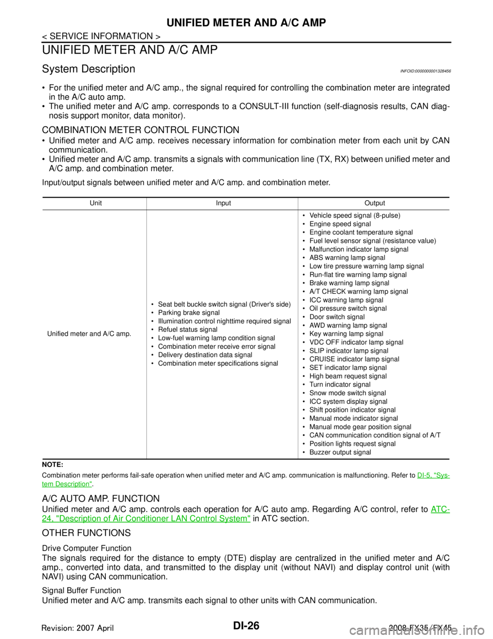
For the unified meter and A/C amp., the signal required for controlling the combination meter are integrated
in the A/C auto amp.
The unified meter and A/C amp. corresponds to a CONS ULT-III function (self-diagnosis results, CAN diag-
nosis support monitor, data monitor).
COMBINATION METER CONTROL FUNCTION
Unified meter and A/C amp. receives necessary information for combination meter from each unit by CAN communication.
Unified meter and A/C amp. transmits a signals with communication line (TX, RX) between unified meter and A/C amp. and combination meter.
Input/output signals between unified meter and A/C amp. and combination meter.
NOTE:
Combination meter performs fail-safe operation when unified meter and A/C amp. communication is malfunctioning. Refer to DI-5, "
Sys-
tem Description".
A/C AUTO AMP. FUNCTION
Unified meter and A/C amp. controls each operation for A/C auto amp. Regarding A/C control, refer to AT C -
24, "Description of Air Conditioner LAN Control System" in ATC section.
OTHER FUNCTIONS
Drive Computer Function
The signals required for the distance to empty (DTE) display are centralized in the unified meter and A/C
amp., converted into data, and transmitted to the disp lay unit (without NAVI) and display control unit (with
NAVI) using CAN communication.
Signal Buffer Function
Unified meter and A/C amp. transmits each signal to other units with CAN communication.
Unit Input Output
Unified meter and A/C amp. Seat belt buckle switch signal (Driver's side)
Parking brake signal
Illumination control nighttime required signal
Refuel status signal
Low-fuel warning lamp condition signal
Combination meter receive error signal
Delivery destination data signal
Combination meter specifications signal Vehicle speed signal (8-pulse)
Engine speed signal
Engine coolant temperature signal
Fuel level sensor signal (resistance value)
Malfunction indicator lamp signal
ABS warning lamp signal
Low tire pressure warning lamp signal
Run-flat tire wa
rning lamp signal
Brake warning lamp signal
A/T CHECK warning lamp signal
ICC warning lamp signal
Oil pressure switch signal
Door switch signal
AWD warning lamp signal
Key warning lamp signal
VDC OFF indicator lamp signal
SLIP indicator lamp signal
CRUISE indicator lamp signal
SET indicator lamp signal
High beam request signal
Turn indicator signal
Snow mode switch signal
ICC system display signal
Shift position indicator signal
Manual mode indicator signal
Manual mode gear position signal
CAN communication condition signal of A/T
Position lights request signal
Buzzer output signal
3AA93ABC3ACD3AC03ACA3AC03AC63AC53A913A773A893A873A873A8E3A773A983AC73AC93AC03AC3
3A893A873A873A8F3A773A9D3AAF3A8A3A8C3A863A9D3AAF3A8B3A8C
Page 1178 of 3924

DI-52
< SERVICE INFORMATION >
WARNING CHIME
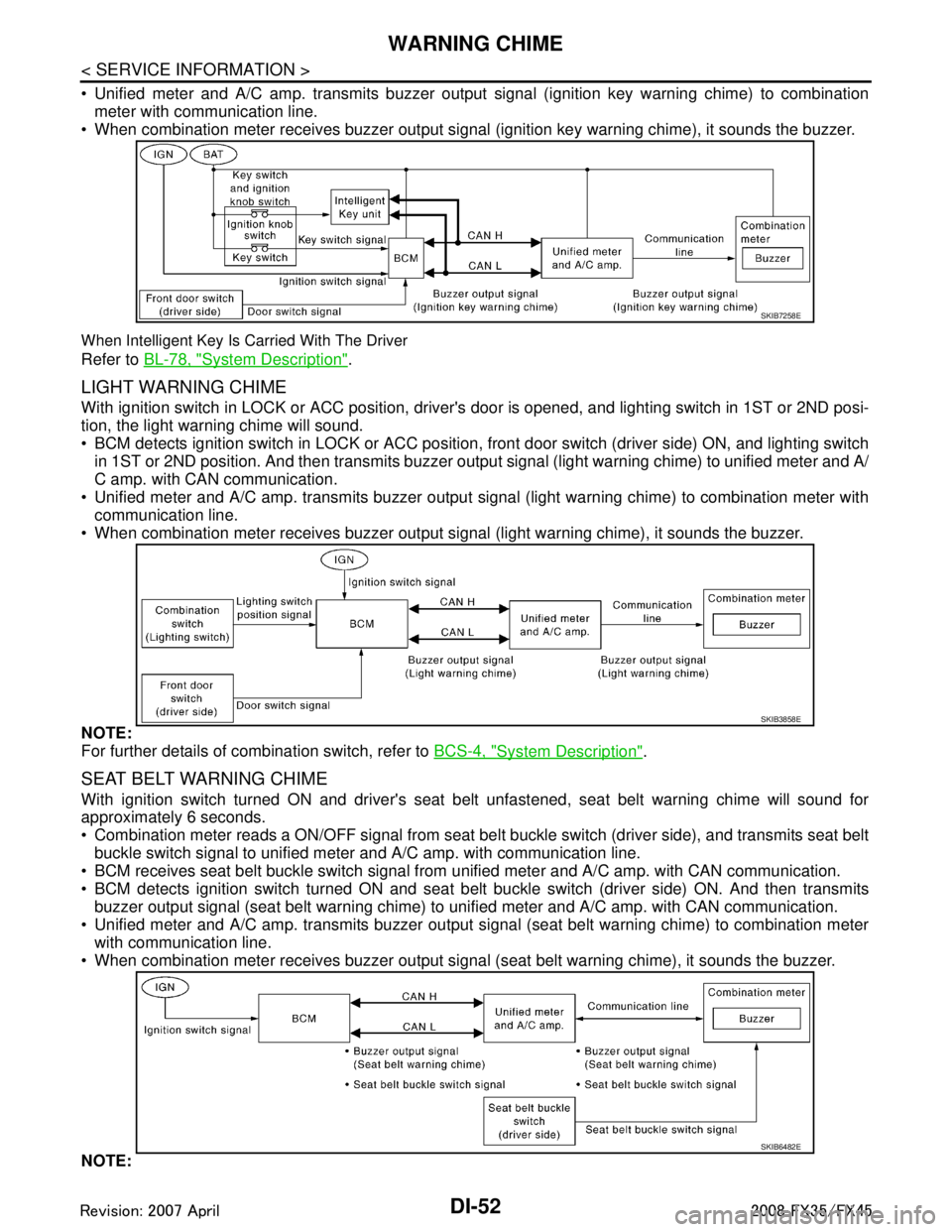
Unified meter and A/C amp. transmits buzzer output signal (ignition key warning chime) to combinationmeter with communication line.
When combination meter receives buzzer output signal (ignition key warning chime), it sounds the buzzer.
When Intelligent Key Is Carried With The Driver
Refer to BL-78, "System Description".
LIGHT WARNING CHIME
With ignition switch in LOCK or ACC position, driver 's door is opened, and lighting switch in 1ST or 2ND posi-
tion, the light warning chime will sound.
BCM detects ignition switch in LOCK or ACC position, front door switch (driver side) ON, and lighting switch
in 1ST or 2ND position. And then transmits buzzer output signal (light warning chime) to unified meter and A/
C amp. with CAN communication.
Unified meter and A/C amp. transmits buzzer output signal (light warning chime) to combination meter with
communication line.
When combination meter receives buzzer output signal (light warning chime), it sounds the buzzer.
NOTE:
For further details of combination switch, refer to BCS-4, "
System Description".
SEAT BELT WARNING CHIME
With ignition switch turned ON and driver's seat belt unfastened, seat belt warning chime will sound for
approximately 6 seconds.
Combination meter reads a ON/OFF signal from seat bel t buckle switch (driver side), and transmits seat belt
buckle switch signal to unified meter and A/C amp. with communication line.
BCM receives seat belt buckle switch signal from unified meter and A/C amp. with CAN communication.
BCM detects ignition switch turned ON and seat bel t buckle switch (driver side) ON. And then transmits
buzzer output signal (seat belt warning chime) to unified meter and A/C amp. with CAN communication.
Unified meter and A/C amp. transmits buzzer output signal (seat belt warning chime) to combination meter with communication line.
When combination meter receives buzzer output signal (seat belt warning chime), it sounds the buzzer.
NOTE:
SKIB7258E
SKIB3858E
SKIB6482E
3AA93ABC3ACD3AC03ACA3AC03AC63AC53A913A773A893A873A873A8E3A773A983AC73AC93AC03AC3
3A893A873A873A8F3A773A9D3AAF3A8A3A8C3A863A9D3AAF3A8B3A8C
Page 1179 of 3924

WARNING CHIMEDI-53
< SERVICE INFORMATION >
C
DE
F
G H
I
J
L
M A
B
DI
N
O P
When ignition key warning chime, light warning chime, and seat belt warning chime should be performed at
the same time, the priorities for each chime are the following.
1. Seat belt warning chime
2. Light warning chime
3. Ignition key warning chime
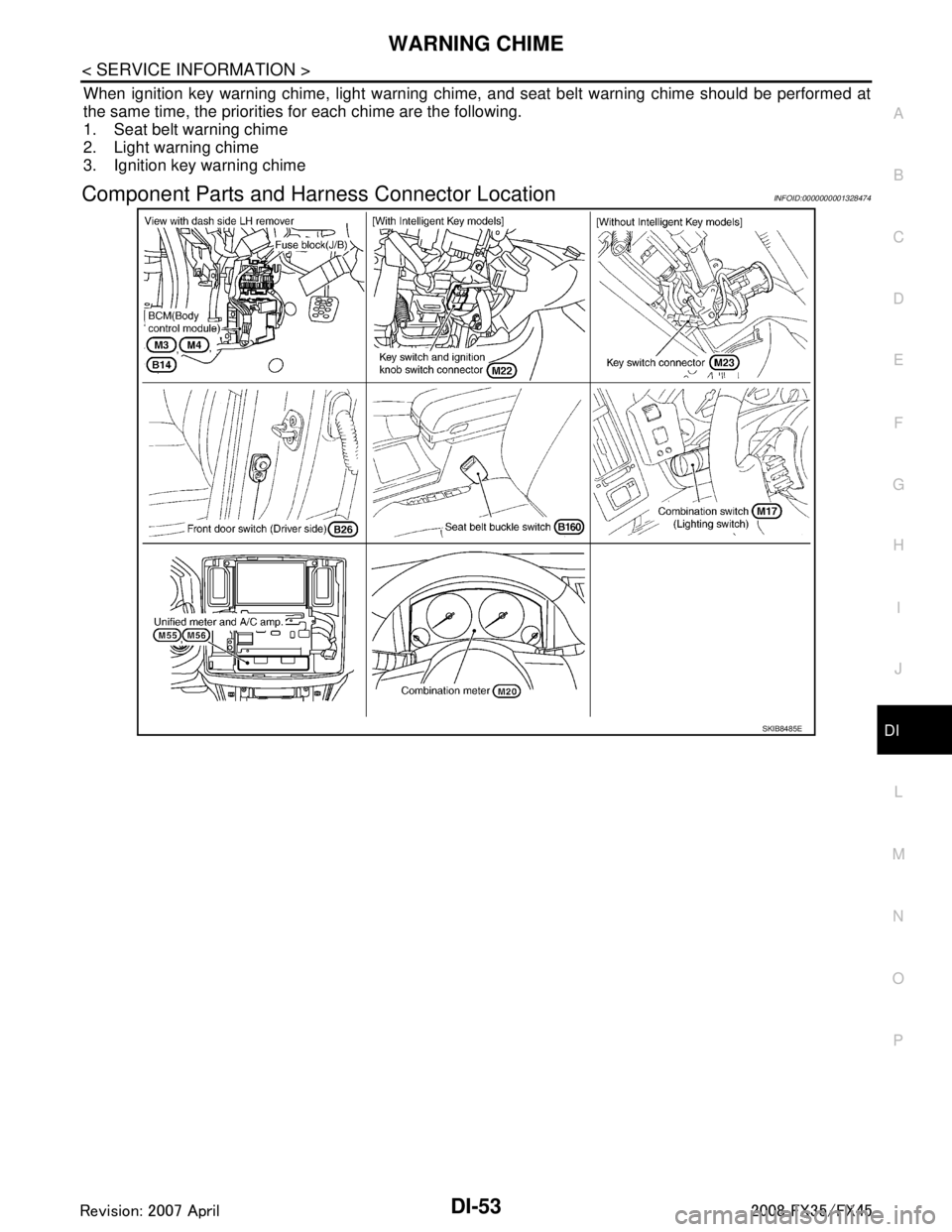
Component Parts and Har ness Connector LocationINFOID:0000000001328474
SKIB8485E
3AA93ABC3ACD3AC03ACA3AC03AC63AC53A913A773A893A873A873A8E3A773A983AC73AC93AC03AC3
3A893A873A873A8F3A773A9D3AAF3A8A3A8C3A863A9D3AAF3A8B3A8C
Page 1183 of 3924

WARNING CHIMEDI-57
< SERVICE INFORMATION >
C
DE
F
G H
I
J
L
M A
B
DI
N
O P
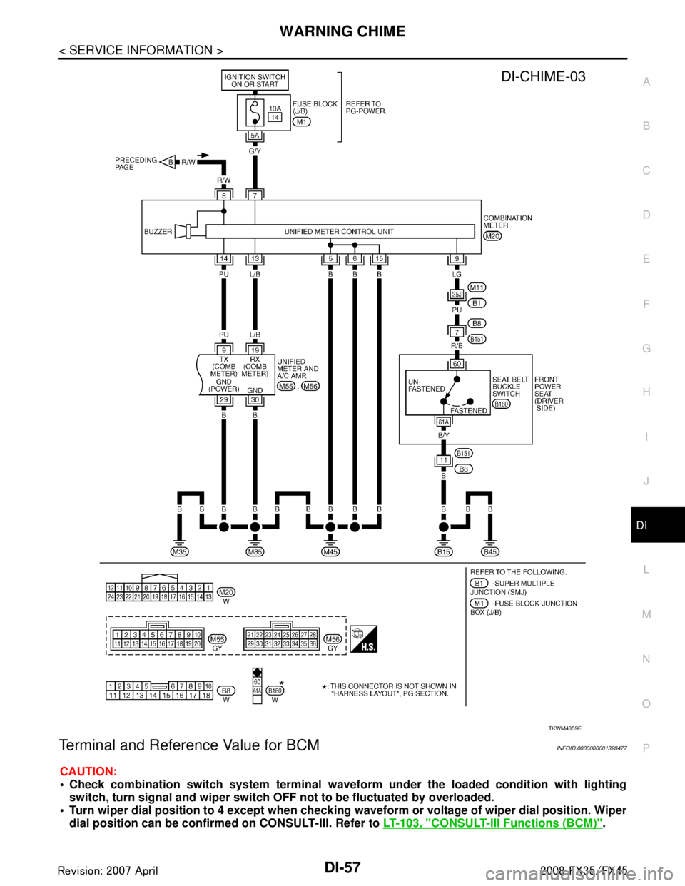
Terminal and Reference Value for BCMINFOID:0000000001328477
CAUTION:
Check combination switch system terminal wavef orm under the loaded condition with lighting
switch, turn signal and wipe r switch OFF not to be fluctuated by overloaded.
Turn wiper dial position to 4 except when checking w aveform or voltage of wiper dial position. Wiper
dial position can be confirmed on CONSULT-III. Refer to LT-103, "
CONSULT-III Functions (BCM)".
TKWM4359E
3AA93ABC3ACD3AC03ACA3AC03AC63AC53A913A773A893A873A873A8E3A773A983AC73AC93AC03AC3
3A893A873A873A8F3A773A9D3AAF3A8A3A8C3A863A9D3AAF3A8B3A8C