2008 INFINITI FX35 service interval
[x] Cancel search: service intervalPage 3462 of 3924

POWER STEERING FLUIDPS-7
< SERVICE INFORMATION >
C
DE
F
H I
J
K L
M A
B
PS
N
O P
POWER STEERING FLUID
Checking Fluid LevelINFOID:0000000001327709
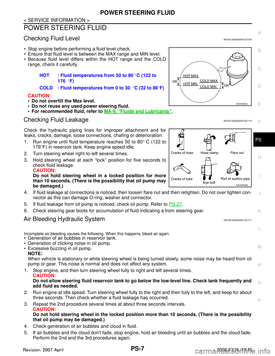
Stop engine before performing a fluid level check.
Ensure that fluid level is between the MAX range and MIN level.
Because fluid level differs within the HOT range and the COLD range, check it carefully.
CAUTION:
Do not overfill the Max level.
Do not reuse any used power steering fluid.
For recommended fluid, refer to MA-9, "
Fluids and Lubricants".
Checking Fluid LeakageINFOID:0000000001327710
Check the hydraulic piping lines for improper attachment and for
leaks, cracks, damage, loose connections, chafing or deterioration.
1. Run engine until fluid temperature reaches 50 to 80 ° C (122 to
176 °F) in reservoir tank. Keep engine speed idle.
2. Turn steering wheel right-to-left several times.
3. Hold steering wheel at each “lock” position for five seconds to check fluid leakage.
CAUTION:
Do not hold steering wheel in a locked position for more
than 10 seconds. (There is the possibility that oil pump may
be damaged.)
4. If fluid leakage at connections is noticed, then loos en flare nut and then retighten. Do not over tighten con-
nector as this can damage O-ring, washer and connector.
5. If fluid leakage from oil pump is noticed, check oil pump. Refer to PS-27
.
6. Check steering gear boots for accumulation of fluid indicating a from steering gear.
Air Bleeding Hydraulic SystemINFOID:0000000001327711
Incomplete air bleeding causes the following. When this happens, bleed air again.
Generation of air bubbles in reservoir tank.
Generation of clicking noise in oil pump.
Excessive buzzing in oil pump. NOTE:
When vehicle is stationary or while steering wheel is being turned slowly, some noise may be heard from oil
pump or gear. This noise is normal and does not affect any system.
1. Stop engine, and then turn steering wheel fully to right and left several times. CAUTION:
Do not allow steering fluid reservoir tank to go below the low-level line. Check tank frequently and
add fluid as needed.
2. Run engine at idle speed. Turn steering wheel fully to the right and then fully to the left, and keep for about
three seconds. Then check whether a fluid leakage has occurred.
3. Repeat the 2nd procedure several times at about three seconds intervals. CAUTION:
Do not hold steering wheel in the locked position more than 10 seconds. (There is the possibility
that oil pump may be damaged.)
4. Check generation of air bubbles and cloud in fluid.
5. If air bubbles and the cloud don't fade, stop engine, hold air bleeding until air bubbles and the cloud fade.
Perform the 2nd and the 3rd procedures again. HOT : Fluid temperatures from 50 to 80
°C (122 to
176 °F)
COLD : Fluid temperatures from 0 to 30 °C (32 to 86 °F)
SGIA0232J
SGIA0506E
3AA93ABC3ACD3AC03ACA3AC03AC63AC53A913A773A893A873A873A8E3A773A983AC73AC93AC03AC3
3A893A873A873A8F3A773A9D3AAF3A8A3A8C3A863A9D3AAF3A8B3A8C
Page 3849 of 3924

ROAD WHEEL TIRE ASSEMBLYWT-9
< SERVICE INFORMATION >
C
DF
G H
I
J
K L
M A
B
WT
N
O P
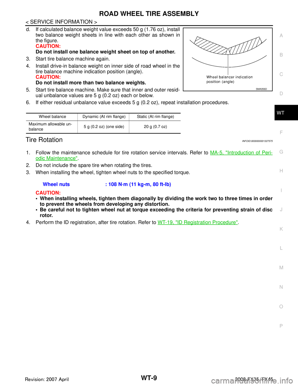
d. If calculated balance weight value exceeds 50 g (1.76 oz), install two balance weight sheets in line with each other as shown in
the figure.
CAUTION:
Do not install one balance weig ht sheet on top of another.
3. Start tire balance machine again.
4. Install drive-in balance weight on inner side of road wheel in the tire balance machine indication position (angle).
CAUTION:
Do not install more than two balance weights.
5. Start tire balance machine. Make sure that inner and outer resid- ual unbalance values are 5 g (0.2 oz) each or below.
6. If either residual unbalance value exceeds 5 g (0.2 oz), repeat installation procedures.
Tire RotationINFOID:0000000001327575
1. Follow the maintenance schedule for tire rotation service intervals. Refer to MA-5, "Introduction of Peri-
odic Maintenance".
2. Do not include the spare tire when rotating the tires.
3. When installing the wheel, tighten wheel nuts to the specified torque.
CAUTION:
When installing wheels, tighten th em diagonally by dividing the work two to three times in order
to prevent the wheels from developing any distortion.
Be careful not to tighten wheel nut at torque exceeding the criteria for preventing strain of disc
rotor.
4. Perform the ID registration, after tire rotation. Refer to WT-19, "
ID Registration Procedure".
Wheel balance Dynamic (At rim flange) Static (At rim flange)
Maximum allowable un-
balance 5 g (0.2 oz) (one side) 20 g (0.7 oz)
SMA056D
Wheel nuts : 108 N·m (11 kg-m, 80 ft-lb)
3AA93ABC3ACD3AC03ACA3AC03AC63AC53A913A773A893A873A873A8E3A773A983AC73AC93AC03AC3
3A893A873A873A8F3A773A9D3AAF3A8A3A8C3A863A9D3AAF3A8B3A8C
Page 3876 of 3924

WW-1
ELECTRICAL
C
DE
F
G H
I
J
L
M
SECTION WW
A
B
WW
N
O P
CONTENTS
WIPER, WASHER & HORN
SERVICE INFORMATION .. ..........................3
PRECAUTION ................................................ .....3
Precaution for Supplemental Restraint System
(SRS) "AIR BAG" and "SEAT BELT PRE-TEN-
SIONER" ............................................................. ......
3
Precaution for Procedure without Cowl Top Cover ......3
FRONT WIPER AND WASHER SYSTEM ..........4
Component Parts and Harness Connector Loca-
tion ...................................................................... ......
4
System Description ...................................................4
CAN Communication System Description .................6
CAN Communication Unit .........................................7
Schematic .................................................................7
Wiring Diagram - WIPER - ........................................8
Terminal and Reference Value for BCM .................10
Terminal and Reference Value for IPDM E/R .........14
How to Proceed with Trouble Diagnosis .................14
Preliminary Check ...................................................14
CONSULT-III Functions (BCM) ...............................15
CONSULT-III Functions (IPDM E/R) .......................16
Front Wiper Does Not Operate ...............................17
Front Wiper Does Not Return to Stop Position .......18
Only Front Wiper Low Does Not Operate ...............19
Only Front Wiper High Does Not Operate ...............20
Only Front Wiper Intermittent Does Not Operate ....21
Front Wiper Interval Time Is Not Controlled by Ve-
hicle Speed .............................................................
21
Front Wiper Intermittent Operation Switch Posi-
tion Cannot Be Adjusted .........................................
22
Wiper Does Not Wipe When Front Washer Oper-
ates .........................................................................
22
After Front Wiper Operate for 10 Seconds, They
Stop for 20 Seconds, and After Repeating the Op-
eration Five Times, They Become Inoperative ........
22
Front Wiper Does Not Stop .....................................23
Removal and Installation of Front Wiper Arms, Ad-
justment of Wiper Arms Stop Location ....................
23
Removal and Installation of Front Wiper Drive As-
sembly ................................................................. ....
24
Disassembly and Assembly of Front Wiper Drive
Assembly ............................................................. ....
25
Washer Nozzle Adjustment .....................................25
Washer Tube Layout ...............................................27
Removal and Installation of Front Washer Nozzle ....27
Removal and Installation of Front Washer Tube
Joint .........................................................................
27
Inspection of Washer Nozzle ...................................27
Inspection of Front Wiper and Washer Switch Cir-
cuit ...........................................................................
28
Removal and Installation of Front Wiper and
Washer Switch .........................................................
28
Removal and Installation of Washer Tank ...............28
Removal and Installation of Front and Rear Wash-
er Pump ...................................................................
29
REAR WIPER AND WASHER SYSTEM ..........30
Component Parts and Harness Connector Loca-
tion ...........................................................................
30
System Description ..................................................30
Wiring Diagram - WIP/ R - .......................................32
Terminal and Reference Value for BCM ..................33
How to Proceed with Trouble Diagnosis ..................35
Preliminary Check ...................................................36
CONSULT-III Functions (BCM) ...............................36
Rear Wiper Does Not Operate ................................37
Rear Wiper Does Not Return to Stop Position ........39
Only Rear Wiper ON Does Not Operate ..................40
Only Rear Wiper INT Does Not Operate .................40
Wiper Does Not Wipe When Rear Washer Oper-
ates ..........................................................................
40
Rear Wipers Do Not Stop ........................................40
Removal and Installation of Rear Wiper Arm, Ad-
justment of Wiper Arms Stop Location ....................
40
Removal and Installation of Rear Wiper Blade ........41
Removal and Installation of Rear Wiper Motor ........42
Washer Nozzle Adjustment .....................................43
Washer Tube Layout ...............................................43
Removal and Installation of Washer Nozzle ............43
Check Valve ............................................................44
3AA93ABC3ACD3AC03ACA3AC03AC63AC53A913A773A893A873A873A8E3A773A983AC73AC93AC03AC3
3A893A873A873A8F3A773A9D3AAF3A8A3A8C3A863A9D3AAF3A8B3A8C
Page 3880 of 3924

FRONT WIPER AND WASHER SYSTEMWW-5
< SERVICE INFORMATION >
C
DE
F
G H
I
J
L
M A
B
WW
N
O P
to BCM terminals 49 and 52
through grounds M35, M45 and M85,
to IPDM E/R terminals 38 and 60
through grounds E21, E50 and E51,
to combination switch terminal 12
through grounds M35, M45 and M85.
LOW SPEED WIPER OPERATION
When wiper switch is in LOW position, BCM detects low speed wiper ON signal by BCM wiper switch reading
function.
BCM sends front wiper request signal (LO) through CAN communication
from BCM terminals 39 and 40
to IPDM E/R terminals 48 and 49.
When IPDM E/R receives front wiper request signal (LO), it turns ON front wiper relay located in IPDM E/R,
power is supplied
through front wiper relay
through front wiper high relay
through IPDM E/R terminal 21
to front wiper motor terminal 1.
Ground is supplied
to front wiper motor terminal 2
through grounds E21, E50 and E51.
With power and ground supplied, the front wiper motor operates at low speed.
HIGH SPEED WIPER OPERATION
When wiper switch is in HI position, BCM detects high speed wiper ON signal by BCM wiper switch reading
function.
BCM sends front wiper request signal (HI) through CAN communication
from BCM terminals 39 and 40
to IPDM E/R terminals 48 and 49.
When IPDM E/R receives front wiper r equest signal (HI), it turns ON front wiper relay (located in IPDM E/R),
power is supplied
through front wiper relay
through front wiper high relay
through IPDM E/R terminal 31
to front wiper motor terminal 4.
Ground is supplied
to front wiper motor terminal 2
through grounds E21, E50 and E51.
With power and ground supplied, the front wiper motor operates at high speed.
INTERMITTENT OPERATION
Front wiper intermittent operation delay interval is det ermined from a combination of 3 switches (intermittent
operation dial position 1, 2, and 3) and vehicle speed signal.
Speed dependent wiper controlled mode can be changed by the function setting of CONSULT-III or display.
During each intermittent operation delay interval, BCM sends front wiper request signal to IPDM E/R.
Wiper Dial Position Setting
Example: For wiper intermittent dial position 1
Wiper intermittent dial position Intermittent operation
interval Combination switch
INT VOLUME 1 INT VOLUME 2 INT VOLUME 3
1Short
↑
↓
Long ON ON ON
2ONONOFF
3ONOFFOFF
4 OFF OFF OFF
5OFFOFFON
6OFFONON
7 OFF ON OFF
3AA93ABC3ACD3AC03ACA3AC03AC63AC53A913A773A893A873A873A8E3A773A983AC73AC93AC03AC3
3A893A873A873A8F3A773A9D3AAF3A8A3A8C3A863A9D3AAF3A8B3A8C
Page 3896 of 3924

FRONT WIPER AND WASHER SYSTEMWW-21
< SERVICE INFORMATION >
C
DE
F
G H
I
J
L
M A
B
WW
N
O P
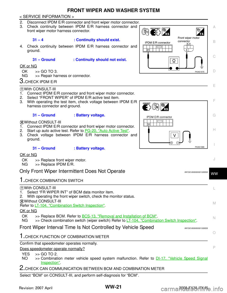
2. Disconnect IPDM E/R connector and front wiper motor connector.
3. Check continuity between IPDM E/R harness connector and front wiper motor harness connector.
4. Check continuity between IPDM E/R harness connector and ground.
OK or NG
OK >> GO TO 3.
NG >> Repair harness or connector.
3.CHECK IPDM E/R
With CONSULT-III
1. Connect IPDM E/R connector and front wiper motor connector.
2. Select “FRONT WIPER” of IPDM E/R active test item.
3. With operating the test item, check voltage between IPDM E/R harness connector and ground.
Without CONSULT-III
1. Connect IPDM E/R connector and front wiper motor connector.
2. Start up auto active test. Refer to PG-20, "
Auto Active Test".
3. Check voltage between IPDM E/R harness connector and
ground.
OK or NG
OK >> Replace front wiper motor.
NG >> Replace IPDM E/R.
Only Front Wiper Intermi ttent Does Not OperateINFOID:0000000001328558
1.CHECK COMBINATION SWITCH
With CONSULT-III
1. Select “FR WIPER INT” of BCM data monitor item.
2. With operating the front wiper switch, check the monitor status.
Without CONSULT-III
Refer to LT-104, "
Combination Switch Inspection".
OK or NG
OK >> Replace BCM. Refer to BCS-13, "Removal and Installation of BCM".
NG >> Check combination switch (wiper switch) Refer to LT-104, "
Combination Switch Inspection".
Front Wiper Interval Time Is Not Controlled by Vehicle SpeedINFOID:0000000001328559
1.CHECK FUNCTION OF COMBINATION METER
Confirm that speedometer operates normally.
Does speedometer operate normally?
YES >> GO TO 2.
NO >> Combination meter vehicle speed system malfunction. Refer to DI-17, "
Vehicle Speed Signal
Inspection".
2.CHECK CAN COMMUNICATION BETWEEN BCM AND COMBINATION METER
Select “BCM” on CONSULT-III, and perform self-diagnosis for “BCM”.
31 – 4 : Continui
ty should exist.
31 – Ground : Continuity should not exist.
PKIA5197E
31 – Ground : Battery voltage.
31 – Ground : Battery voltage.
PKIA5198E
3AA93ABC3ACD3AC03ACA3AC03AC63AC53A913A773A893A873A873A8E3A773A983AC73AC93AC03AC3
3A893A873A873A8F3A773A9D3AAF3A8A3A8C3A863A9D3AAF3A8B3A8C