Page 3721 of 3924

SE-82
< SERVICE INFORMATION >
AUTOMATIC DRIVE POSITIONER
When voltage signal dose not appear with a constant voltage (approx. 5V), replace automatic
driver seat control unit.
When voltage signal dose not appear with a constant voltage (approx. 0V), replace driver seat
control unit.
4.CHECK DRIVER SEAT CONTROL UNIT
Dose the automatic drive positioner operate, when the driver seat control unit exchanged?
Does seat memory function operate?
YES >> Replace automatic drive positioner control unit.
NG >> Replace driver seat control unit.
Check Lumbar Support CircuitINFOID:0000000001328144
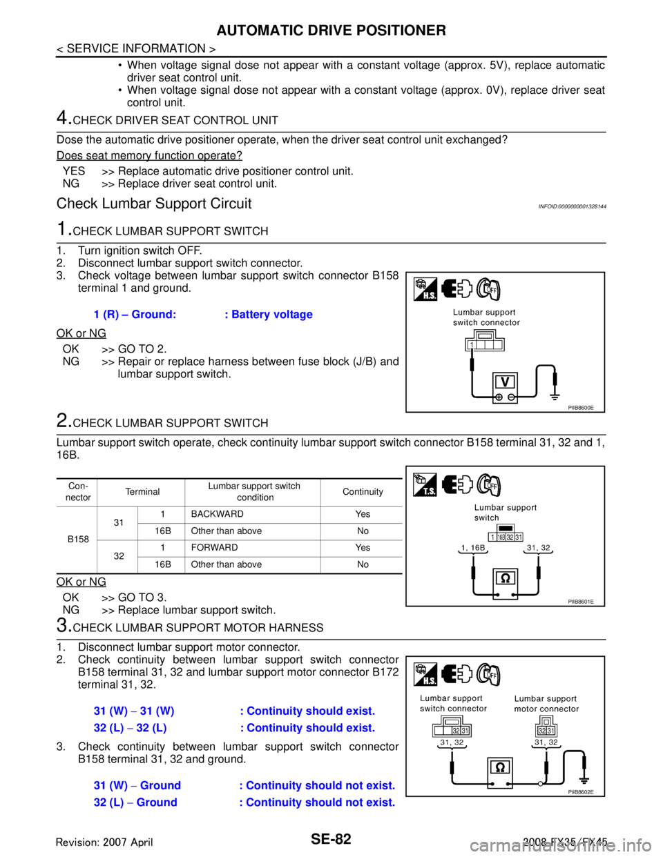
1.CHECK LUMBAR SUPPORT SWITCH
1. Turn ignition switch OFF.
2. Disconnect lumbar support switch connector.
3. Check voltage between lumbar support switch connector B158 terminal 1 and ground.
OK or NG
OK >> GO TO 2.
NG >> Repair or replace harness between fuse block (J/B) and lumbar support switch.
2.CHECK LUMBAR SUPPORT SWITCH
Lumbar support switch operate, check continuity lum bar support switch connector B158 terminal 31, 32 and 1,
16B.
OK or NG
OK >> GO TO 3.
NG >> Replace lumbar support switch.
3.CHECK LUMBAR SUPPORT MOTOR HARNESS
1. Disconnect lumbar support motor connector.
2. Check continuity between lumbar support switch connector B158 terminal 31, 32 and lumbar support motor connector B172
terminal 31, 32.
3. Check continuity between lumbar support switch connector B158 terminal 31, 32 and ground.1 (R) – Ground: : Battery voltage
PIIB8600E
Con-
nector Te r m i n a l
Lumbar support switch
condition Continuity
B158 31
1 BACKWARD Yes
16B Other than above No
32 1FORWARD Yes
16B Other than above No
PIIB8601E
31 (W) − 31 (W) : Continuity should exist.
32 (L) − 32 (L) : Continuity should exist.
31 (W) − Ground : Continuity should not exist.
32 (L) − Ground : Continuity should not exist.
PIIB8602E
3AA93ABC3ACD3AC03ACA3AC03AC63AC53A913A773A893A873A873A8E3A773A983AC73AC93AC03AC3
3A893A873A873A8F3A773A9D3AAF3A8A3A8C3A863A9D3AAF3A8B3A8C
Page 3761 of 3924
![INFINITI FX35 2008 Service Manual
SRS-24
< SERVICE INFORMATION >
TROUBLE DIAGNOSIS
Trouble Diagnosis with CONSULT-III
INFOID:0000000001524168
DIAGNOSTIC PROCEDURE
DTC No. Index (“SELF-DIAG [ CURRENT]” “SELF-DIAG [PAST]” or INFINITI FX35 2008 Service Manual
SRS-24
< SERVICE INFORMATION >
TROUBLE DIAGNOSIS
Trouble Diagnosis with CONSULT-III
INFOID:0000000001524168
DIAGNOSTIC PROCEDURE
DTC No. Index (“SELF-DIAG [ CURRENT]” “SELF-DIAG [PAST]” or](/manual-img/42/57017/w960_57017-3760.png)
SRS-24
< SERVICE INFORMATION >
TROUBLE DIAGNOSIS
Trouble Diagnosis with CONSULT-III
INFOID:0000000001524168
DIAGNOSTIC PROCEDURE
DTC No. Index (“SELF-DIAG [ CURRENT]” “SELF-DIAG [PAST]” or TROUBLE DIAG RECORD)
Air bag is deployed.
Seat belt pre-tensioner is deployed. Go to
SRS-47, "For Frontal Colli-
sion" or SRS-48, "For Side Collision"
Diagnosis sensor unit is malfunction-
ing.
Air bag power supply circuit is mal-
functioning.
SRS air bag warning lamp circuit is malfunctioning. Go to
SRS-32, "
Trouble Diagnosis:
"AIR BAG" Warning Lamp Does Not
Turn OFF".
Diagnosis sensor unit is malfunction- ing.
Air bag warning lamp circuit is mal-
functioning. Go to
SRS-32, "
Trouble Diagnosis:
"AIR BAG" Warning Lamp Does Not
Turn ON".
“AIR BAG” warning lamp operation — User mode
—
SRS condition Reference item
SHIA0013E
SHIA0014E
Diagnostic mode Description
SELF-DIAG RESULT The self-d iagnosis result is Displayed. (SELF-DIAG [ CURRENT], [PAST], [RECORD])
ECU DISCRIMINATED No. The parts number of diagnosis sensor units displayed.
Diagnostic item Explanation Repair order
“Recheck SRS at each replacement”
NO DTC IS DETECT-
ED. When malfunction is in-
dicated by the “AIR
BAG” warning lamp in
User mode. Low battery voltage (Less than 9V)
Self-diagnostic result “SELF-DIAG
[PAST]” (previously stored in the
memory) might not be erased after re-
pair.
Intermittent malfunction has been de- tected in the past. Go to
SRS-21, "
CONSULT-III Func-
tion".
No malfunction is detected. —
DIAGNOSIS SENSOR
UNIT (CONTROL UNIT)
[B1001-B1015] Diagnosis sensor is out of order. Replace diagnosis sensor unit.
(ACU)
3AA93ABC3ACD3AC03ACA3AC03AC63AC53A913A773A893A873A873A8E3A773A983AC73AC93AC03AC3
3A893A873A873A8F3A773A9D3AAF3A8A3A8C3A863A9D3AAF3A8B3A8C
Page 3780 of 3924

SIDE AIR BAG (SATELLITE) SENSOR
SRS-43
< SERVICE INFORMATION >
C
D E
F
G
I
J
K L
M A
B
SRS
N
O P
SIDE AIR BAG (S ATELLITE) SENSOR
Removal and InstallationINFOID:0000000001327769
WARNING:
Before servicing SRS, turn igniti on switch OFF, disconnect both ba ttery cables and wait at least 3
minutes.
Do not use air tools or el ectric tools for servicing.
REMOVAL
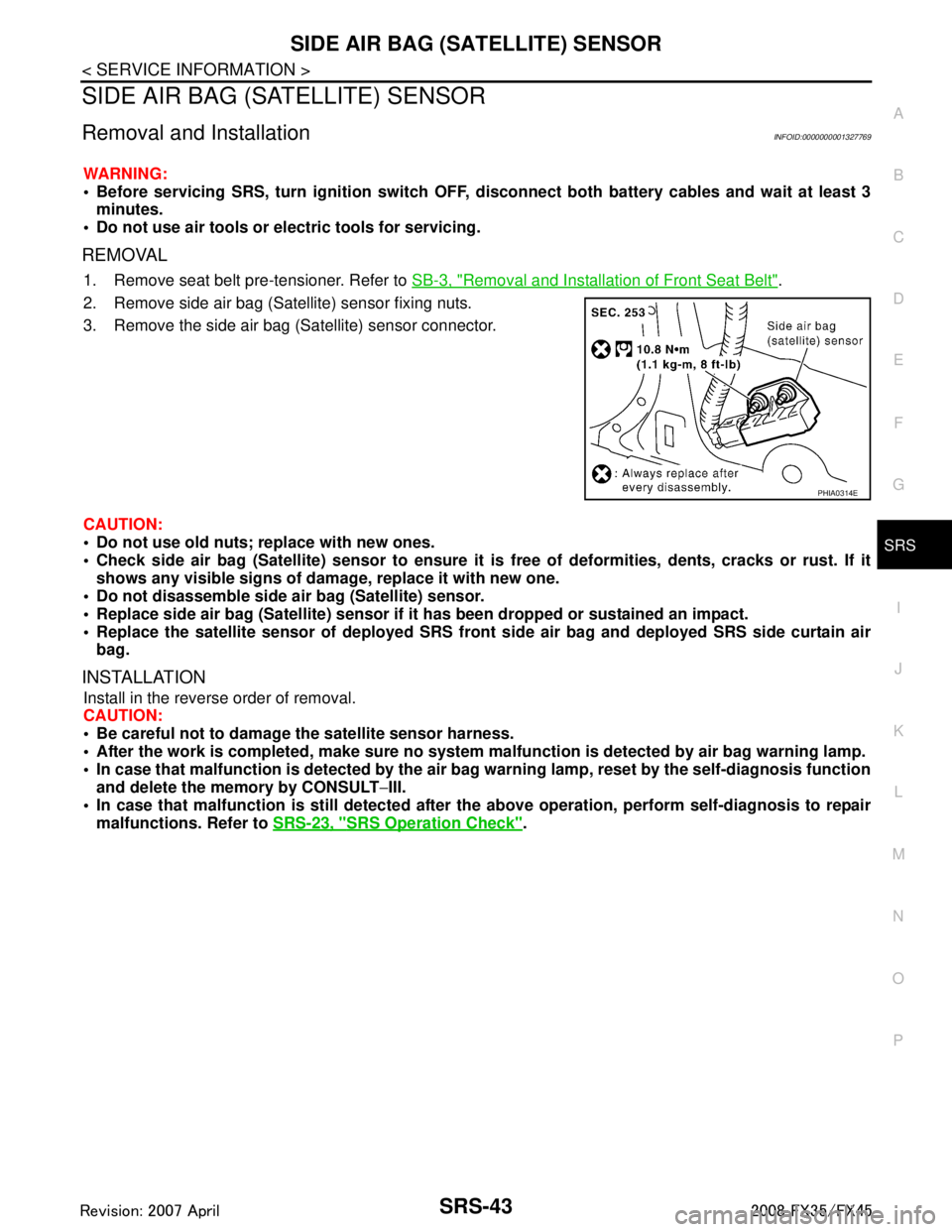
1. Remove seat belt pre-tensioner. Refer to SB-3, "Removal and Installation of Front Seat Belt".
2. Remove side air bag (Satellite) sensor fixing nuts.
3. Remove the side air bag (Satellite) sensor connector.
CAUTION:
Do not use old nuts; replace with new ones.
Check side air bag (Satellite) senso r to ensure it is free of deformities, dents, cracks or rust. If it
shows any visible signs of da mage, replace it with new one.
Do not disassemble side ai r bag (Satellite) sensor.
Replace side air bag (Satellite) sensor if it has been dropped or sustained an impact.
Replace the satellite sensor of de ployed SRS front side air bag and deployed SRS side curtain air
bag.
INSTALLATION
Install in the reverse order of removal.
CAUTION:
Be careful not to damage the satellite sensor harness.
After the work is completed, make sure no system malfunction is detected by air bag warning lamp.
In case that malfunction is detected by the air ba g warning lamp, reset by the self-diagnosis function
and delete the memory by CONSULT −III.
In case that malfunction is still detected after th e above operation, perform self-diagnosis to repair
malfunctions. Refer to SRS-23, "
SRS Operation Check".
PHIA0314E
3AA93ABC3ACD3AC03ACA3AC03AC63AC53A913A773A893A873A873A8E3A773A983AC73AC93AC03AC3
3A893A873A873A8F3A773A9D3AAF3A8A3A8C3A863A9D3AAF3A8B3A8C
Page 3781 of 3924

SRS-44
< SERVICE INFORMATION >
DIAGNOSIS SENSOR UNIT
DIAGNOSIS SENSOR UNIT
Removal and InstallationINFOID:0000000001327771
WARNING:
Before servicing SRS, turn ignition switch OFF, disconnect both ba ttery cables and wait at least 3
minutes.
Do not use air tools or el ectric tools for servicing.
REMOVAL
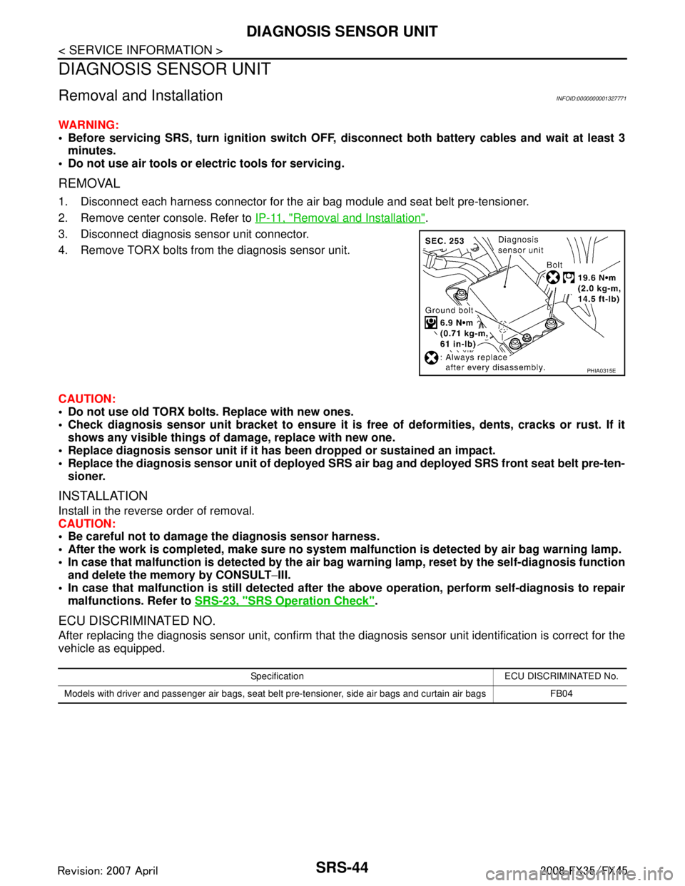
1. Disconnect each harness connector for the ai r bag module and seat belt pre-tensioner.
2. Remove center console. Refer to IP-11, "
Removal and Installation".
3. Disconnect diagnosis sensor unit connector.
4. Remove TORX bolts from the diagnosis sensor unit.
CAUTION:
Do not use old TORX bolts. Replace with new ones.
Check diagnosis sensor unit bracket to ensure it is free of deformities, dents, cracks or rust. If it
shows any visible things of damage, replace with new one.
Replace diagnosis sensor unit if it has been dropped or sustained an impact.
Replace the diagnosis sensor unit of deployed SRS air bag and deployed SRS front seat belt pre-ten-
sioner.
INSTALLATION
Install in the reverse order of removal.
CAUTION:
Be careful not to damage the diagnosis sensor harness.
After the work is completed, make sure no system malfunction is detected by air bag warning lamp.
In case that malfunction is detected by the air ba g warning lamp, reset by the self-diagnosis function
and delete the memory by CONSULT −III.
In case that malfunction is still de tected after the above operation, perform self-diagnosis to repair
malfunctions. Refer to SRS-23, "
SRS Operation Check".
ECU DISCRIMINATED NO.
After replacing the diagnosis sensor unit, confirm that t he diagnosis sensor unit identification is correct for the
vehicle as equipped.
PHIA0315E
Specification ECU DISCRIMINATED No.
Models with driver and passenger air bags, seat belt pre-tensioner, side air bags and curtain air bags FB04
3AA93ABC3ACD3AC03ACA3AC03AC63AC53A913A773A893A873A873A8E3A773A983AC73AC93AC03AC3
3A893A873A873A8F3A773A9D3AAF3A8A3A8C3A863A9D3AAF3A8B3A8C
Page:
< prev 1-8 9-16 17-24