2008 INFINITI FX35 run flat
[x] Cancel search: run flatPage 3070 of 3924
![INFINITI FX35 2008 Service Manual
LAN-50
< SERVICE INFORMATION >[CAN]
TROUBLE DIAGNOSIS
High beam request signal T R R
Horn chirp signal T R
Ignition switch signal T R R
Key fob door unlock signal T R
Key fob ID signal T R
Key switch INFINITI FX35 2008 Service Manual
LAN-50
< SERVICE INFORMATION >[CAN]
TROUBLE DIAGNOSIS
High beam request signal T R R
Horn chirp signal T R
Ignition switch signal T R R
Key fob door unlock signal T R
Key fob ID signal T R
Key switch](/manual-img/42/57017/w960_57017-3069.png)
LAN-50
< SERVICE INFORMATION >[CAN]
TROUBLE DIAGNOSIS
High beam request signal T R R
Horn chirp signal T R
Ignition switch signal T R R
Key fob door unlock signal T R
Key fob ID signal T R
Key switch signal T R
Low beam request signal T R
Oil pressure switch signalRT
TR
Position light request signal R T R R
Rear window defogger switch signal T R
Run flat tire warning lamp signal T R
Sleep wake up signal TRRR
RT
Theft warning horn request signal T R
Tire pressure warning lamp signal T R
Turn indicator signal T R
Alarm request signal R T
Back door open request signal R T
Door lock/unlock request signal R T
Ignition knob switch signal R T
Key warning signal T R
Power window open request signal R T
Steering angle sensor signal T R
Snow mode switch signal R T
Turn LED burnout status signal R T
Distance to empty signal R T
Fuel level low warning signal R T
Fuel level sensor signal R T
Manual mode shift down signal R T
Manual mode shift up signal R T
Manual mode signal R T
Not manual mode signal R T
Parking brake switch signal R R T
Stop lamp switch signal R R T
Vehicle speed signal RRT
R RRRR T R
A/T shift schedule change demand signal R T
ABS operation signal T
ABS warning lamp signal RT
Brake warning lamp signal RT
SLIP indicator lamp signal RT
TCS operation signal T
Signal name/Connecting unit
ECM
4WD
DISP TCM
BCM
I-KEY
STRG M&AABS
ADP
IPDM-E
3AA93ABC3ACD3AC03ACA3AC03AC63AC53A913A773A893A873A873A8E3A773A983AC73AC93AC03AC3
3A893A873A873A8F3A773A9D3AAF3A8A3A8C3A863A9D3AAF3A8B3A8C
Page 3072 of 3924
![INFINITI FX35 2008 Service Manual
LAN-52
< SERVICE INFORMATION >[CAN]
TROUBLE DIAGNOSIS
ICC operation signal R T
ICC system display signal T R
ICC warning lamp signal T R
A/T CHECK indicator lamp signal T R
A/T self-diagnosis signal INFINITI FX35 2008 Service Manual
LAN-52
< SERVICE INFORMATION >[CAN]
TROUBLE DIAGNOSIS
ICC operation signal R T
ICC system display signal T R
ICC warning lamp signal T R
A/T CHECK indicator lamp signal T R
A/T self-diagnosis signal](/manual-img/42/57017/w960_57017-3071.png)
LAN-52
< SERVICE INFORMATION >[CAN]
TROUBLE DIAGNOSIS
ICC operation signal R T
ICC system display signal T R
ICC warning lamp signal T R
A/T CHECK indicator lamp signal T R
A/T self-diagnosis signal R T
Current gear position signal R T R
Manual mode indicator signal R T R
Output shaft revolution signal R R T R
P range signal R T R R
Shift position indicator signal R T R
Turbine revolution signal R R T
A/C switch signal R T
Blower fan motor switch signal R T
Day time running light request signal T R
Door lock/unlock status signal T R
Door switch signal R T R R R R
Front fog light request signal T R
Front wiper request signal R T R
High beam request signal T R R
Horn chirp signal T R
Ignition switch signal T R R
Key fob door unlock signal T R
Key fob ID signal T R
Key switch signal T R
Low beam request signal T R
Oil pressure switch signalRT
TR
Position light request signal R T R R
Rear window defogger switch signal T R
Run flat tire warning lamp signal T R
Sleep wake up signal TRRR
RT
Theft warning horn request signal T R
Tire pressure warning lamp signal T R
Turn indicator signal T R R
Alarm request signal R T
Back door open request signal R T
Door lock/unlock request signal R T
Ignition knob switch signal R T
Key warning signal T R
Power window open request signal R T
Steering angle sensor signal T R
Distance to empty signal R T Signal name/Connecting unit
ECM
4WD
DISP ICC
TCM
BCM
I-KEY
LANE
STRG M&A
ABS
LASER ADP
IPDM-E
3AA93ABC3ACD3AC03ACA3AC03AC63AC53A913A773A893A873A873A8E3A773A983AC73AC93AC03AC3
3A893A873A873A8F3A773A9D3AAF3A8A3A8C3A863A9D3AAF3A8B3A8C
Page 3564 of 3924

RFD-22
< SERVICE INFORMATION >
REAR FINAL DRIVE ASSEMBLY
Never change the total amount of washers as it will change the bearing preload.
Companion Flange Runout
1. Fit a test indicator to the inner side of companion flange (socket
diameter).
2. Rotate companion flange to check for runout.
3. If the runout value is outside t he runout limit, follow the proce-
dure below to adjust.
a. Check for runout while changing the phase between companion flange and drive pinion by 90 ° step, and search for the position
where the runout is the minimum.
b. If the runout value is still outside of the limit after the phase has been changed, possible cause will be an assembly malfunction of drive pinion and pinion bearing and
malfunction of pinion bearing. Check for these items and repair if necessary.
c. If the runout value is still outside of the limit after the check and repair, replace companion flange.
DISASSEMBLY
Differential Assembly
1. Drain gear oil, if necessary.
2. Remove side flange.
3. Remove rear cover mounting bolts.
4. Remove rear cover to insert the seal cutter between gear carrier and rear cover.
CAUTION:
Be careful not to damage the mating surface.
Never insert flat-bladed screwdriver, this way damage the
mating surface.
5. Using two 45 mm (1.77 in) spacers, mount carrier on the attach- ment.Runout limit: 0.08 mm (0.0031 in)
PDIA0490E
Tool number A: KV10111100 (J-37228)
PDIA0756J
Tool number A: KV38100800 (J-25604-01)
PDIA0757J
3AA93ABC3ACD3AC03ACA3AC03AC63AC53A913A773A893A873A873A8E3A773A983AC73AC93AC03AC3
3A893A873A873A8F3A773A9D3AAF3A8A3A8C3A863A9D3AAF3A8B3A8C
Page 3841 of 3924

WT-1
SUSPENSION
C
DF
G H
I
J
K L
M
SECTION WT
A
B
WT
N
O PCONTENTS
ROAD WHEELS & TIRES
SERVICE INFORMATION .. ..........................2
INDEX FOR DTC ............................................ .....2
DTC No. Index .................................................... ......2
PRECAUTIONS ...................................................3
Precaution for Supplemental Restraint System
(SRS) "AIR BAG" and "SEAT BELT PRE-TEN-
SIONER" ............................................................. ......
3
Precaution .................................................................3
Service Notice or Precaution .....................................4
PREPARATION ...................................................5
Special Service Tool ........................................... ......5
Commercial Service Tool ..........................................5
NOISE, VIBRATION AND HARSHNESS
(NVH) TROUBLESHOOTING .............................
6
NVH Troubleshooting Chart ................................ ......6
ROAD WHEEL ....................................................7
Inspection ............................................................ ......7
ROAD WHEEL TIRE ASSEMBLY ......................8
Balancing Wheels (Bonding Weight Type) .......... ......8
Tire Rotation ..............................................................9
TIRE PRESSURE MONITORING SYSTEM .......10
System Component ............................................. ....10
System Description .................................................10
CAN COMMUNICATION ....................................13
System Description ............................................. ....13
TROUBLE DIAGNOSES ....................................14
Schematic ........................................................... ....14
Wiring Diagram- T/WARN - .....................................15
Control Unit Input/Output Signal Standard ..............17
ID Registration Procedure ................................... ....19
Transmitter Wake Up Operation ..............................20
Self-Diagnosis .........................................................20
CONSULT-III Function (BCM) .................................22
How to Perform Trouble Diagnosis for Quick and
Accurate Repair .......................................................
24
Preliminary Check ...................................................25
Malfunction Code/Symptom Chart ...........................26
TROUBLE DIAGNOSIS FOR SELF-DIAG-
NOSTIC ITEMS .................................................
28
Transmitter or Control Unit (BCM) ...........................28
Transmitter - 1 .........................................................28
Transmitter - 2 .........................................................29
Vehicle Speed Signal ..............................................29
TROUBLE DIAGNOSIS FOR SYMPTOMS ......30
Low Tire Pressure Warning Lamp Does Not Come
On When Ignition Switch Is Turned On ...................
30
Low Tire Pressure Warning Lamp Stays On When
Ignition Switch Is Turned On ............................... ....
30
Low Tire Pressure Warning Lamp Blinks When Ig-
nition Switch Is Turned On ......................................
31
Run-Flat Tire Warning Lamp Stays On When Igni-
tion Switch Is Turned On .........................................
32
Turn Signal Lamp Blinks When Ignition Switch Is
Turned On ...............................................................
32
ID Registration Cannot Be Completed ....................32
REMOVAL AND INSTALLATION .....................33
Transmitter ..............................................................33
SERVICE DATA AND SPECIFICATIONS
(SDS) .................................................................
35
Road Wheel .............................................................35
Tire ..........................................................................35
3AA93ABC3ACD3AC03ACA3AC03AC63AC53A913A773A893A873A873A8E3A773A983AC73AC93AC03AC3
3A893A873A873A8F3A773A9D3AAF3A8A3A8C3A863A9D3AAF3A8B3A8C
Page 3847 of 3924

ROAD WHEELWT-7
< SERVICE INFORMATION >
C
DF
G H
I
J
K L
M A
B
WT
N
O P
ROAD WHEEL
InspectionINFOID:0000000001327573
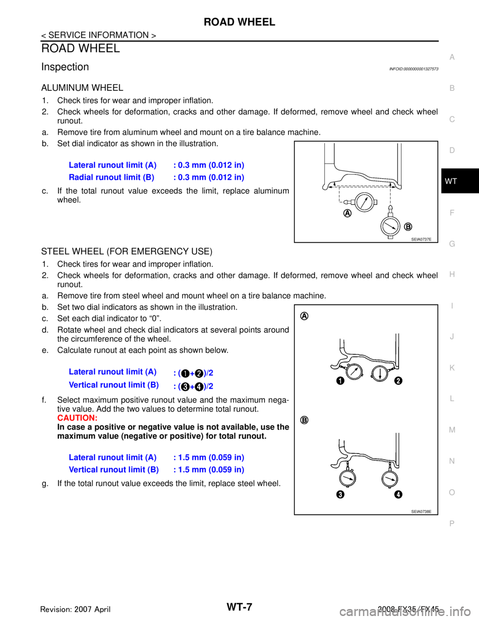
ALUMINUM WHEEL
1. Check tires for wear and improper inflation.
2. Check wheels for deformation, cracks and other damage. If deformed, remove wheel and check wheel runout.
a. Remove tire from aluminum wheel and mount on a tire balance machine.
b. Set dial indicator as shown in the illustration.
c. If the total runout value exceeds the limit, replace aluminum wheel.
STEEL WHEEL (FOR EMERGENCY USE)
1. Check tires for wear and improper inflation.
2. Check wheels for deformation, cracks and other damage. If deformed, remove wheel and check wheelrunout.
a. Remove tire from steel wheel and mount wheel on a tire balance machine.
b. Set two dial indicators as shown in the illustration.
c. Set each dial indicator to “0”.
d. Rotate wheel and check dial indicators at several points around the circumference of the wheel.
e. Calculate runout at each point as shown below.
f. Select maximum positive runout value and the maximum nega- tive value. Add the two values to determine total runout.
CAUTION:
In case a positive or negative val ue is not available, use the
maximum value (negative or positive) for total runout.
g. If the total runout value exceeds the limit, replace steel wheel.
Lateral runout limit (A) : 0.3 mm (0.012 in)
Radial runout limit (B) : 0.3 mm (0.012 in)
SEIA0737E
Lateral runout limit (A)
: ( + )/2
Vertical runout limit (B) : ( + )/2
Lateral runout limit (A) : 1.5 mm (0.059 in)
Vertical runout limit (B) : 1.5 mm (0.059 in)
SEIA0738E
3AA93ABC3ACD3AC03ACA3AC03AC63AC53A913A773A893A873A873A8E3A773A983AC73AC93AC03AC3
3A893A873A873A8F3A773A9D3AAF3A8A3A8C3A863A9D3AAF3A8B3A8C
Page 3851 of 3924

TIRE PRESSURE MONITORING SYSTEMWT-11
< SERVICE INFORMATION >
C
DF
G H
I
J
K L
M A
B
WT
N
O P
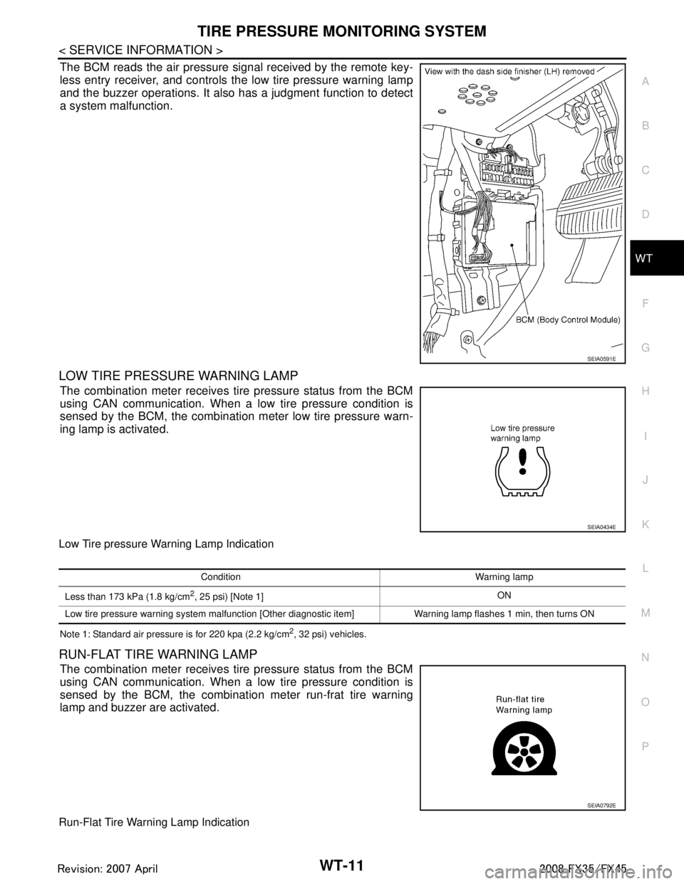
The BCM reads the air pressure signal received by the remote key-
less entry receiver, and controls the low tire pressure warning lamp
and the buzzer operations. It also has a judgment function to detect
a system malfunction.
LOW TIRE PRESSURE WARNING LAMP
The combination meter receives tire pressure status from the BCM
using CAN communication. When a low tire pressure condition is
sensed by the BCM, the combination meter low tire pressure warn-
ing lamp is activated.
Low Tire pressure Warning Lamp Indication
Note 1: Standard air pressure is for 220 kpa (2.2 kg/cm2, 32 psi) vehicles.
RUN-FLAT TIRE WARNING LAMP
The combination meter receives tire pressure status from the BCM
using CAN communication. When a low tire pressure condition is
sensed by the BCM, the combination meter run-frat tire warning
lamp and buzzer are activated.
Run-Flat Tire Warning Lamp Indication
SEIA0591E
SEIA0434E
Condition Warning lamp
Less than 173 kPa (1.8 kg/cm
2, 25 psi) [Note 1] ON
Low tire pressure warning system malfunction [Other diagnostic item] Warning lamp flashes 1 min, then turns ON
SEIA0792E
3AA93ABC3ACD3AC03ACA3AC03AC63AC53A913A773A893A873A873A8E3A773A983AC73AC93AC03AC3
3A893A873A873A8F3A773A9D3AAF3A8A3A8C3A863A9D3AAF3A8B3A8C
Page 3862 of 3924

WT-22
< SERVICE INFORMATION >
TROUBLE DIAGNOSES
NOTE:
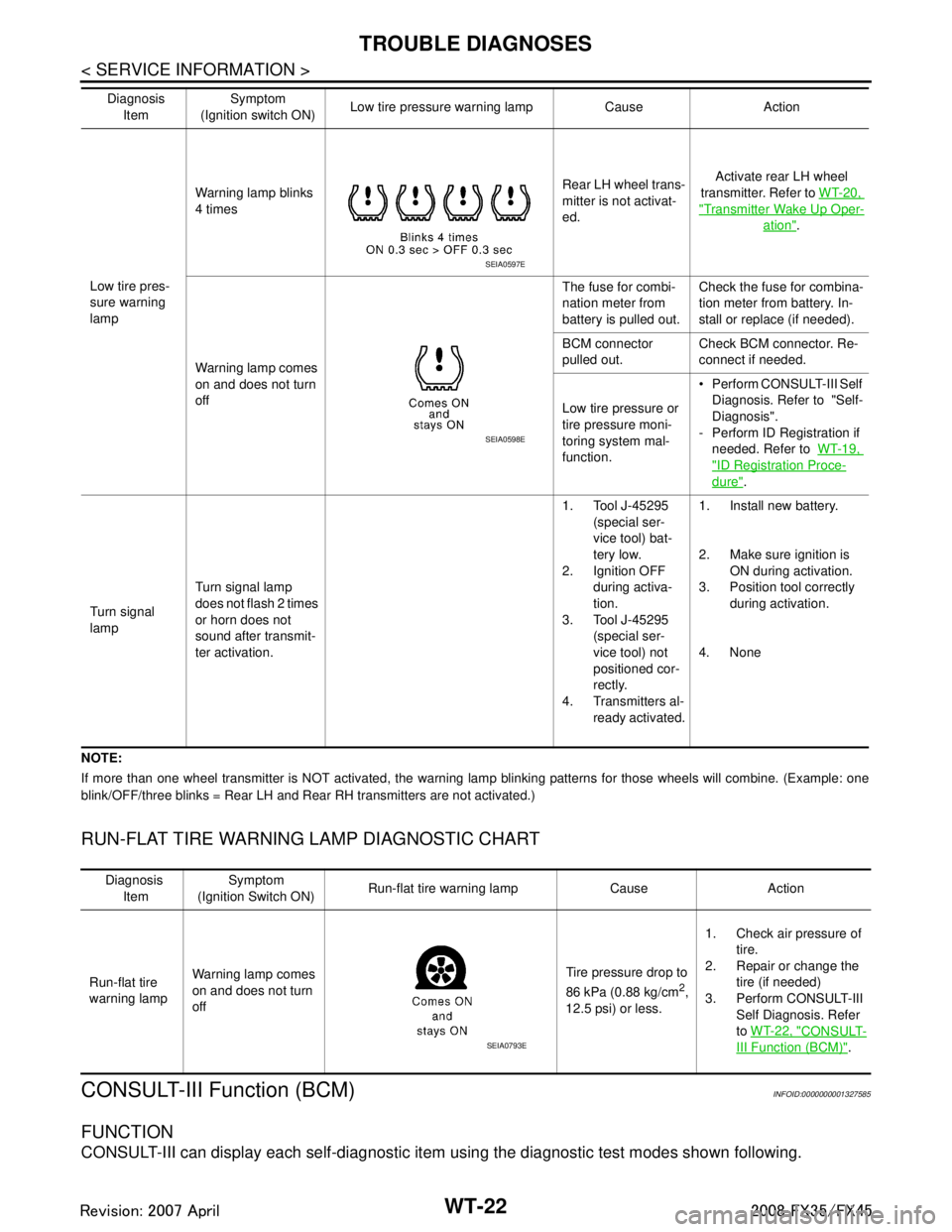
If more than one wheel transmitter is NOT activated, the warning lamp blinking patterns for those wheels will combine. (Example: one
blink/OFF/three blinks = Rear LH and Rear RH transmitters are not activated.)
RUN-FLAT TIRE WARNING LAMP DIAGNOSTIC CHART
CONSULT-III Function (BCM)INFOID:0000000001327585
FUNCTION
CONSULT-III can display each self-diagnostic item using the diagnostic test modes shown following.
Low tire pres-
sure warning
lampWarning lamp blinks
4 times
Rear LH wheel trans-
mitter is not activat-
ed.Activate rear LH wheel
transmitter. Refer to WT-20,
"Transmitter Wake Up Oper-
ation".
Warning lamp comes
on and does not turn
off The fuse for combi-
nation meter from
battery is pulled out.
Check the fuse for combina-
tion meter from battery. In-
stall or replace (if needed).
BCM connector
pulled out. Check BCM connector. Re-
connect if needed.
Low tire pressure or
tire pressure moni-
toring system mal-
function. Perform CONSULT-III Self
Diagnosis. Refer to "Self-
Diagnosis".
- Perform ID Registration if needed. Refer to WT-19,
"ID Registration Proce-
dure".
Turn signal
lamp Turn signal lamp
does not flash 2 times
or horn does not
sound after transmit-
ter activation. 1. Tool J-45295
(special ser-
vice tool) bat-
tery low.
2. Ignition OFF
during activa-
tion.
3. Tool J-45295
(special ser-
vice tool) not
positioned cor-
rectly.
4. Transmitters al- ready activated. 1. Install new battery.
2. Make sure ignition is
ON during activation.
3. Position tool correctly during activation.
4. None
Diagnosis
Item Symptom
(Ignition switch ON) Low tire pressure wa
rning lamp Cause Action
SEIA0597E
SEIA0598E
Diagnosis
Item Symptom
(Ignition Switch ON) Run-flat tire warning lamp Cause Action
Run-flat tire
warning lamp Warning lamp comes
on and does not turn
off Tire pressure drop to
86 kPa (0.88 kg/cm
2,
12.5 psi) or less. 1. Check air pressure of
tire.
2. Repair or change the
tire (if needed)
3. Perform CONSULT-III Self Diagnosis. Refer
to WT-22, "
CONSULT-
III Function (BCM)".SEIA0793E
3AA93ABC3ACD3AC03ACA3AC03AC63AC53A913A773A893A873A873A8E3A773A983AC73AC93AC03AC3
3A893A873A873A8F3A773A9D3AAF3A8A3A8C3A863A9D3AAF3A8B3A8C
Page 3866 of 3924

WT-26
< SERVICE INFORMATION >
TROUBLE DIAGNOSES
OK or NG
OK >> GO TO 4.
NG >> Repair or replace damaged parts.
4.CHECK TRANSMITTER TOOL
Check activation tool battery.
OK or NG
OK >> Perform self-diagnosis.
NG >> Replace activation tool battery.
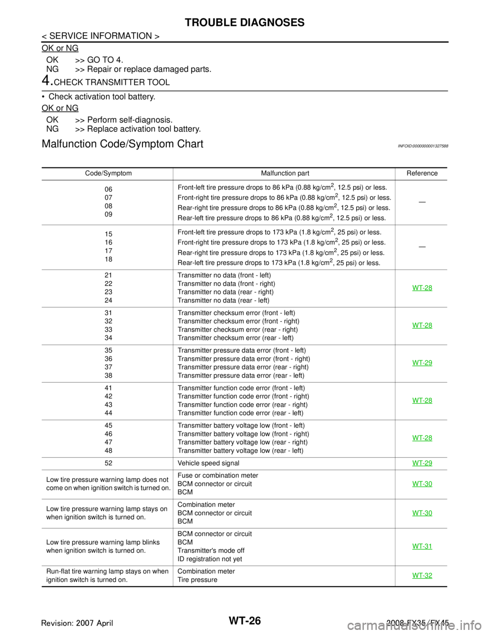
Malfunction Code/Symptom ChartINFOID:0000000001327588
Code/Symptom Malfunction part Reference
06
07
08
09 Front-left tire pressure drops to 86 kPa (0.88 kg/cm
2, 12.5 psi) or less.
Front-right tire pressure drops to 86 kPa (0.88 kg/cm2, 12.5 psi) or less.
Rear-right tire pre ssure drops to 86 kPa (0.88 kg/cm2, 12.5 psi) or less.
Rear-left tire pressure drops to 86 kPa (0.88 kg/cm2, 12.5 psi) or less. —
15
16
17
18 Front-left tire pressure drops to 173 kPa (1.8 kg/cm
2, 25 psi) or less.
Front-right tire pressure drops to 173 kPa (1.8 kg/cm2, 25 psi) or less.
Rear-right tire pre ssure drops to 173 kPa (1.8 kg/cm2, 25 psi) or less.
Rear-left tire pressure drops to 173 kPa (1.8 kg/cm2, 25 psi) or less. —
21
22
23
24 Transmitter no data (front - left)
Transmitter no data (front - right)
Transmitter no data (rear - right)
Transmitter no data (rear - left)
WT-28
31
32
33
34Transmitter checksum e
rror (front - left)
Transmitter checksum e rror (front - right)
Transmitter checksum error (rear - right)
Transmitter checksum error (rear - left) WT-28
35
36
37
38Transmitter pressure data
error (front - left)
Transmitter pressure data error (front - right)
Transmitter pressure data error (rear - right)
Transmitter pressure data error (rear - left) WT-29
41
42
43
44Transmitter function code error (front - left)
Transmitter function code
error (front - right)
Transmitter function code error (rear - right)
Transmitter function code error (rear - left) WT-28
45
46
47
48Transmitter battery voltage low (front - left)
Transmitter battery voltage low (front - right)
Transmitter battery voltage low (rear - right)
Transmitter battery voltage low (rear - left)
WT-28
52 Vehicle speed signal
WT-29
Low tire pressure warning lamp does not
come on when ignition switch is turned on.Fuse or combination meter
BCM connector or circuit
BCM
WT-30
Low tire pressure warning lamp stays on
when ignition switch is turned on.Combination meter
BCM connector or circuit
BCM
WT-30
Low tire pressure wa
rning lamp blinks
when ignition switch is turned on. BCM connector or circuit
BCM
Transmitter's mode off
ID registration not yet
WT-31
Run-flat tire warning lamp stays on when
ignition switch is turned on.
Combination meter
Tire pressure
WT-32
3AA93ABC3ACD3AC03ACA3AC03AC63AC53A913A773A893A873A873A8E3A773A983AC73AC93AC03AC3
3A893A873A873A8F3A773A9D3AAF3A8A3A8C3A863A9D3AAF3A8B3A8C