2008 INFINITI FX35 oil filter
[x] Cancel search: oil filterPage 2668 of 3924
![INFINITI FX35 2008 Service Manual
EM-184
< SERVICE INFORMATION >[VK45DE]
OIL PAN AND OIL STRAINER
Do not spill engine oil on drive belts.
6. Drain engine coolant. Refer to CO-37, "
Changing Engine Coolant".
CAUTION:
Perform this INFINITI FX35 2008 Service Manual
EM-184
< SERVICE INFORMATION >[VK45DE]
OIL PAN AND OIL STRAINER
Do not spill engine oil on drive belts.
6. Drain engine coolant. Refer to CO-37, "
Changing Engine Coolant".
CAUTION:
Perform this](/manual-img/42/57017/w960_57017-2667.png)
EM-184
< SERVICE INFORMATION >[VK45DE]
OIL PAN AND OIL STRAINER
Do not spill engine oil on drive belts.
6. Drain engine coolant. Refer to CO-37, "
Changing Engine Coolant".
CAUTION:
Perform this step when engine is cold.
Do not spill engine coolant on drive belts.
7. Remove drive belts. Refer to EM-170, "
Component".
8. Remove auto tensioner of power steering oil pump belt. Refer to EM-172, "
Drive Belt Auto Tensioner and
Idler Pulley".
9. Remove power steering oil pump with piping connect ed, and temporarily secure it aside with ropes or
equivalent. Refer to PS-27, "
On-Vehicle Inspection and Service".
10. Remove A/C compressor with piping connected, and tem porarily secure it aside with ropes or equivalent.
Refer to ATC-121, "
Component".
11. Remove A/C compressor fitting bolts, and install A/C compressor temporarily on vehicle side with ropes or equivalent.
12. Remove harness of lower side of oil pan.
13. Remove crankshaft position sensor (POS) from transmission. CAUTION:
Handle carefully to avoid dropping and shocks.
Do not disassemble it.
Do not allow metal powder to adhere to magnetic part at sensor tip.
Do not place sensors in a location wh ere they are exposed to magnetism.
14. Install engine slinger and hang engine assembly to secure position. Refer to EM-237, "
Component".
15. Remove front suspension member with power tool. Refer to FSU-16, "
Removal and Installation".
16. Remove front final drive assembly. Refer to FFD-14, "
Removal and Installation (VQ35DE Models)".
17. Remove oil filter. Refer to LU-26, "
Removal and Installation".
18. Disconnect oil cooler water hoses, and remove oil cooler water pipe and oil cooler. Refer to LU-27, "
Com-
ponent".
19. Remove oil pan as the follows:
a. Remove rear plate cover.
b. Remove transmission joint bolts which pierce oil pan. Refer to AT-243, "
Removal and Installation (AWD
Models)".
c. Loosen mounting bolts with power tool in reverse order as shown in the figure.
NOTE:
Disregard the numerical order No. 11 and 17 in removal.
d. Insert seal cutter (SST) between oil pan and cylinder block. Slide seal cutter by tapping on the side of seal cutter with ham-
mer. Remove oil pan.
CAUTION:
Be careful not to damage the mating surfaces.
Do not insert screwdriver, th is will damage the mating
surface.
e. Remove O-rings from bottom of oil pump and front cover.
20. As necessary, pull axle pipe from oil pan.
PBIC0194E
SEM365E
3AA93ABC3ACD3AC03ACA3AC03AC63AC53A913A773A893A873A873A8E3A773A983AC73AC93AC03AC3
3A893A873A873A8F3A773A9D3AAF3A8A3A8C3A863A9D3AAF3A8B3A8C
Page 2842 of 3924

FL-10
< SERVICE INFORMATION >
FUEL TANK
FUEL TANK
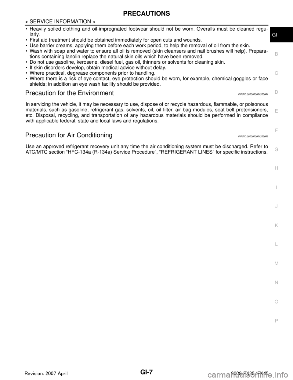
ComponentINFOID:0000000001327110
Removal and InstallationINFOID:0000000001327111
REMOVAL
WARNING:
Be sure to read “General Precautions” when working on the fuel system. Refer to FL-3, "
General Pre-
caution".
Drain fuel from fuel tank if necessary. Refer to FL-4, "
Removal and Installation".
Perform work on level place.
1. Perform steps 2 to 7 of “REMOVAL” in “ FUEL LEVEL SENSOR UNIT, FUEL FILTER AND FUEL PUMP
ASSEMBLY” on main and sub fuel level sensor units. Refer to FL-4, "
Removal and Installation".
2. Remove tunnel stay. Refer to RSU-5, "
On-Vehicle Inspection and Service".
3. Remove exhaust front tube, center muffler and main muffler. Refer to EX-3, "
Checking Exhaust System".
4. Remove insulator.
5. Remove propeller shaft. Refer to PR-7, "
On-Vehicle Inspection".
6. Remove parking rear brake cables. Refer to PB-4, "
Component".
7. Compress coil spring and remove coil spring.
8. Remove rear suspension assembly.
9. Remove fuel tank protector.
1. Grommet 2. Fuel filler cap 3. Clip
4. Fuel filler tube protector 5. Fuel tank mounting band 6. Fuel tank protector
7. Insulator 8. Fuel tank 9. Vent tube
10. Vent hose 11. EVAP hose 12. Vent hose
13. Fuel filler hose 14. Fuel filler tube
PBIC1580E
3AA93ABC3ACD3AC03ACA3AC03AC63AC53A913A773A893A873A873A8E3A773A983AC73AC93AC03AC3
3A893A873A873A8F3A773A9D3AAF3A8A3A8C3A863A9D3AAF3A8B3A8C
Page 2869 of 3924

PRECAUTIONSGI-7
< SERVICE INFORMATION >
C
DE
F
G H
I
J
K L
M B
GI
N
O P
Heavily soiled clothing and oil-impregnated footwear should not be worn. Overalls must be cleaned regu-
larly.
First aid treatment should be obtai ned immediately for open cuts and wounds.
Use barrier creams, applying them before each work period, to help the removal of oil from the skin.
Wash with soap and water to ensure all oil is removed (skin cleansers and nail brushes will help). Prepara- tions containing lanolin replace the natural skin oils which have been removed.
Do not use gasoline, kerosene, diesel fuel, gas oil, thinners or solvents for cleaning skin.
If skin disorders develop, obtain medical advice without delay.
Where practical, degrease components prior to handling.
Where there is a risk of eye contact, eye protecti on should be worn, for example, chemical goggles or face
shields; in addition an eye wash facility should be provided.
Precaution for the EnvironmentINFOID:0000000001325661
In servicing the vehicle, it may be necessary to use, dispose of or recycle hazardous, flammable, or poisonous
materials, such as gasoline, refrigerant gas, solvents, oil, oil filter, air bag modules, seat belt pretensioners,
etc. Disposal, recycling, and transportation of any haz ardous materials should be performed in compliance
with applicable federal, state and local laws and regulations.
Precaution for Air ConditioningINFOID:0000000001325662
Use an approved refrigerant recovery unit any time t he air conditioning system must be discharged. Refer to
ATC/MTC section “HFC-134a (R-134a) Service Procedure”, “REFRIGERANT LINES” for specific instructions.
3AA93ABC3ACD3AC03ACA3AC03AC63AC53A913A773A893A873A873A8E3A773A983AC73AC93AC03AC3
3A893A873A873A8F3A773A9D3AAF3A8A3A8C3A863A9D3AAF3A8B3A8C
Page 3286 of 3924

LU-1
ENGINE
C
DE
F
G H
I
J
K L
M
SECTION LU
A
LU
N
O P
CONTENTS
ENGINE LUBRICATION SYSTEM
VQ35DE
SERVICE INFORMATION .. ..........................
2
PRECAUTIONS .............................................. .....2
Precaution for Liquid Gasket ............................... ......2
PREPARATION ...................................................3
Special Service Tool ........................................... ......3
Commercial Service Tool ..........................................3
LUBRICATION SYSTEM ....................................4
Lubrication Circuit ............................................... ......4
System Chart ............................................................4
ENGINE OIL ........................................................5
Inspection ............................................................ ......5
Changing Engine Oil .................................................7
OIL FILTER .........................................................8
Removal and Installation ..................................... ......8
OIL FILTER BRACKET (AWD) ..........................10
Component .......................................................... ....10
Removal and Installation .........................................10
OIL COOLER ......................................................12
Component .......................................................... ....12
Removal and Installation .........................................13
OIL PUMP ...........................................................15
Component .......................................................... ....15
Removal and Installation .........................................15
Disassembly and Assembly ....................................15
SERVICE DATA AND SPECIFICATIONS
(SDS) ..................................................................
18
Standard and Limit .............................................. ....18
VK45DE
SERVICE INFORMATION .. .........................
19
PRECAUTIONS .................................................19
Precaution for Liquid Gasket ............................... ....19
PREPARATION .................................................20
Special Service Tool ................................................20
Commercial Service Tool ........................................20
LUBRICATION SYSTEM ..................................21
Lubrication Circuit ....................................................21
System Chart ...........................................................22
ENGINE OIL ......................................................23
Inspection ................................................................23
Changing Engine Oil ................................................24
OIL FILTER .......................................................26
Removal and Installation .........................................26
OIL COOLER ....................................................27
Component ..............................................................27
Removal and Installation .........................................27
OIL PUMP .........................................................29
Component ..............................................................29
Removal and Installation .........................................29
Disassembly and Assembly .....................................30
SERVICE DATA AND SPECIFICATIONS
(SDS) .................................................................
32
Standard and Limit ..................................................32
3AA93ABC3ACD3AC03ACA3AC03AC63AC53A913A773A893A873A873A8E3A773A983AC73AC93AC03AC3
3A893A873A873A8F3A773A9D3AAF3A8A3A8C3A863A9D3AAF3A8B3A8C
Page 3288 of 3924
![INFINITI FX35 2008 Service Manual
PREPARATIONLU-3
< SERVICE INFORMATION > [VQ35DE]
C
D
E
F
G H
I
J
K L
M A
LU
NP
O
PREPARATION
Special Service ToolINFOID:0000000001325809
The actual shapes of Kent-Moore t
ools may differ from those o INFINITI FX35 2008 Service Manual
PREPARATIONLU-3
< SERVICE INFORMATION > [VQ35DE]
C
D
E
F
G H
I
J
K L
M A
LU
NP
O
PREPARATION
Special Service ToolINFOID:0000000001325809
The actual shapes of Kent-Moore t
ools may differ from those o](/manual-img/42/57017/w960_57017-3287.png)
PREPARATIONLU-3
< SERVICE INFORMATION > [VQ35DE]
C
D
E
F
G H
I
J
K L
M A
LU
NP
O
PREPARATION
Special Service ToolINFOID:0000000001325809
The actual shapes of Kent-Moore t
ools may differ from those of special service tools illustrated here.
Commercial Service ToolINFOID:0000000001325810
Tool number
(Kent-Moore No.)
Tool name Description
ST25051001
(J25695-1)
Oil pressure gauge Measuring oil pressure
Maximum measuring range: 2,452 kPa (25
kg-cm
2, 356 psi)
ST25052000
(J25695-2)
Hose Adapting oil pressure gauge to oil pan (upper)
KV10115801
(J38956)
Oil filter wrench Removing and installing oil filter
a: 64.3 mm (2.531 in)
NT050
S-NT559
S-NT375
Tool name
Description
Power tools Loosening nuts and bolts
Deep socket Removing and installing oil pressure switch
a: 26 mm (1.02 in)
PBIC0190E
PBIC2072E
3AA93ABC3ACD3AC03ACA3AC03AC63AC53A913A773A893A873A873A8E3A773A983AC73AC93AC03AC3
3A893A873A873A8F3A773A9D3AAF3A8A3A8C3A863A9D3AAF3A8B3A8C
Page 3290 of 3924
![INFINITI FX35 2008 Service Manual
ENGINE OILLU-5
< SERVICE INFORMATION > [VQ35DE]
C
D
E
F
G H
I
J
K L
M A
LU
NP
O
ENGINE OIL
InspectionINFOID:0000000001325813
ENGINE OIL LEVEL
NOTE:
Before starting engine, put vehicle horizontally an INFINITI FX35 2008 Service Manual
ENGINE OILLU-5
< SERVICE INFORMATION > [VQ35DE]
C
D
E
F
G H
I
J
K L
M A
LU
NP
O
ENGINE OIL
InspectionINFOID:0000000001325813
ENGINE OIL LEVEL
NOTE:
Before starting engine, put vehicle horizontally an](/manual-img/42/57017/w960_57017-3289.png)
ENGINE OILLU-5
< SERVICE INFORMATION > [VQ35DE]
C
D
E
F
G H
I
J
K L
M A
LU
NP
O
ENGINE OIL
InspectionINFOID:0000000001325813
ENGINE OIL LEVEL
NOTE:
Before starting engine, put vehicle horizontally and check
the engine oil level. If engine is already started, stop
it and allow 10 minutes before checking.
1. Pull out oil level gauge and wipe it clean.
2. Insert oil level gauge and make sure the engine oil level is within the range shown in the figure.
3. If it is out of range, adjust it.
NOTE:
When checking the engine oil level, insert oil level gauge with its
tip aligned with oil level gauge guide on cylinder head. (In figure,
air cleaner case and air duct are removed.)
ENGINE OIL APPEARANCE
Check engine oil for white turbidity or heavy contamination.
If engine oil becomes turbid and white, it is highl y probable that it is contaminated with engine coolant.
Repair or replace damaged parts.
ENGINE OIL LEAKAGE
Check for engine oil leakage around the following areas:
Oil pans (lower and upper)
Oil pan drain plug
Oil pressure switch
Oil filter
Oil filter bracket (AWD models)
Oil cooler
Water pump cover
Chain tensioner cover
Intake valve timing control cover and intake valve timing control solenoid valve
Mating surface between cylinder head and rocker cover
Mating surface between front timing chain case and rear timing chain case
Mating surface between rear timing chain case and cylinder head
Mating surface between rear timing chain case and cylinder block
Mating surface between rear timing chain case and oil pan (upper)
Mating surface between cylinder block and cylinder head
Crankshaft oil seals (front and rear)
Camshaft position sensor (PHASE)
OIL PRESSURE CHECK
PBIC3101E
KBIA1343E
3AA93ABC3ACD3AC03ACA3AC03AC63AC53A913A773A893A873A873A8E3A773A983AC73AC93AC03AC3
3A893A873A873A8F3A773A9D3AAF3A8A3A8C3A863A9D3AAF3A8B3A8C
Page 3292 of 3924
![INFINITI FX35 2008 Service Manual
ENGINE OILLU-7
< SERVICE INFORMATION > [VQ35DE]
C
D
E
F
G H
I
J
K L
M A
LU
NP
Oc. After warming up engine, make sure there is no leakage of engine oil with running engine.
Changing Engine OilINFOID:0 INFINITI FX35 2008 Service Manual
ENGINE OILLU-7
< SERVICE INFORMATION > [VQ35DE]
C
D
E
F
G H
I
J
K L
M A
LU
NP
Oc. After warming up engine, make sure there is no leakage of engine oil with running engine.
Changing Engine OilINFOID:0](/manual-img/42/57017/w960_57017-3291.png)
ENGINE OILLU-7
< SERVICE INFORMATION > [VQ35DE]
C
D
E
F
G H
I
J
K L
M A
LU
NP
Oc. After warming up engine, make sure there is no leakage of engine oil with running engine.
Changing Engine OilINFOID:0000000001325814
WARNING:
Be careful not to get burn yourself, as engine oil may be hot.
Prolonged and repeated contact with used engine
oil may cause skin cancer. Try to avoid direct skin
contact with used engine oil. If skin contact is made, wash thorough ly with soap or hand cleaner as
soon as possible.
1. Remove front engine undercover with power tool.
2. Warm up the engine, and check for engine oil leakage from engine components. Refer to LU-5, "
Inspec-
tion".
3. Stop the engine and wait for 10 minutes.
4. Loosen oil filler cap and then remove drain plug.
5. Drain engine oil.
6. Install drain plug with new washer. Refer to EM-30, "
Component (2WD Models)".
CAUTION:
Be sure to clean drain plug and install with new washer.
7. Refill with new engine oil. Engine oil specificat ion and viscosity:
Refer to MA-9, "
Fluids and Lubricants".
Engine oil capacity (Approximate):
Unit: (US qt, lmp qt)
CAUTION:
When filling engine oil, do not pull out oil level gauge.
The refill capacity depends on the engine oi l temperature and drain time. Use these specifica-
tions for reference only.
Always use oil level gauge to determine the proper amount of engine oil in engine.
8. Warm up the engine and check area around drain plug and oil filter for engine oil leakage.
9. Stop the engine and wait for 10 minutes.
10. Check the engine oil level. Refer to LU-5, "
Inspection".
Oil pressure switch:
: 14.8 N·m (1.5 kg-m, 11 ft-lb)
Oil pan drain plug: : 34.3 N·m (3.5 kg-m, 25 ft-lb)
Drain and refill With oil filter change 4.7 (5, 4-1/8)
Without oil filter change 4.4 (4-5/8, 3-7/8)
Dry engine (Overhaul) 5.4 (5-3/4, 4-3/4)
3AA93ABC3ACD3AC03ACA3AC03AC63AC53A913A773A893A873A873A8E3A773A983AC73AC93AC03AC3
3A893A873A873A8F3A773A9D3AAF3A8A3A8C3A863A9D3AAF3A8B3A8C
Page 3293 of 3924
![INFINITI FX35 2008 Service Manual
LU-8
< SERVICE INFORMATION >[VQ35DE]
OIL FILTER
OIL FILTER
Removal and InstallationINFOID:0000000001325815
REMOVAL
1. Remove front engine undercover with power tool.
2. Using oil filter wrench (SST), INFINITI FX35 2008 Service Manual
LU-8
< SERVICE INFORMATION >[VQ35DE]
OIL FILTER
OIL FILTER
Removal and InstallationINFOID:0000000001325815
REMOVAL
1. Remove front engine undercover with power tool.
2. Using oil filter wrench (SST),](/manual-img/42/57017/w960_57017-3292.png)
LU-8
< SERVICE INFORMATION >[VQ35DE]
OIL FILTER
OIL FILTER
Removal and InstallationINFOID:0000000001325815
REMOVAL
1. Remove front engine undercover with power tool.
2. Using oil filter wrench (SST), remove oil filter.
CAUTION:
Oil filter is provided with relief valve. Use Genuine NissanOil Filter or equivalent.
Be careful not to get burned when engine and engine oil may be hot.
When removing, prepare a sh op cloth to absorb any
engine oil leakage or spillage.
Do not allow engine oil to adhere to drive belts.
Completely wipe off any engine oil that adheres to engine
and vehicle.
INSTALLATION
1. Remove foreign materials adhering to oil filter installation surface.
2. Apply engine oil to the oil seal contact surface of new oil filter.
3. Screw oil filter manually until it touches the installation surface,
then tighten it by 2/3 turn. Or tighten to the specification.
INSPECTION AFTER INSTALLATION
1. Check the engine oil level. Refer to LU-5, "Inspection".
SBIA0454E
SBIA0455E
SMA010
Oil filter:
: 17.7 N·m (1.8 kg-m, 13 ft-lb)
SMA229B
3AA93ABC3ACD3AC03ACA3AC03AC63AC53A913A773A893A873A873A8E3A773A983AC73AC93AC03AC3
3A893A873A873A8F3A773A9D3AAF3A8A3A8C3A863A9D3AAF3A8B3A8C