Page 1200 of 3924

DI-74
< SERVICE INFORMATION >
LANE DEPARTURE WARNING SYSTEM
The target may not be detected when there is the same pattern of black and white as the target when
the pattern is within 1 m (3.28 ft) from either si de and upward/downward position from the target. (It
is desirable that the vehicle is positioned on the opposite side of a single-color wall.)
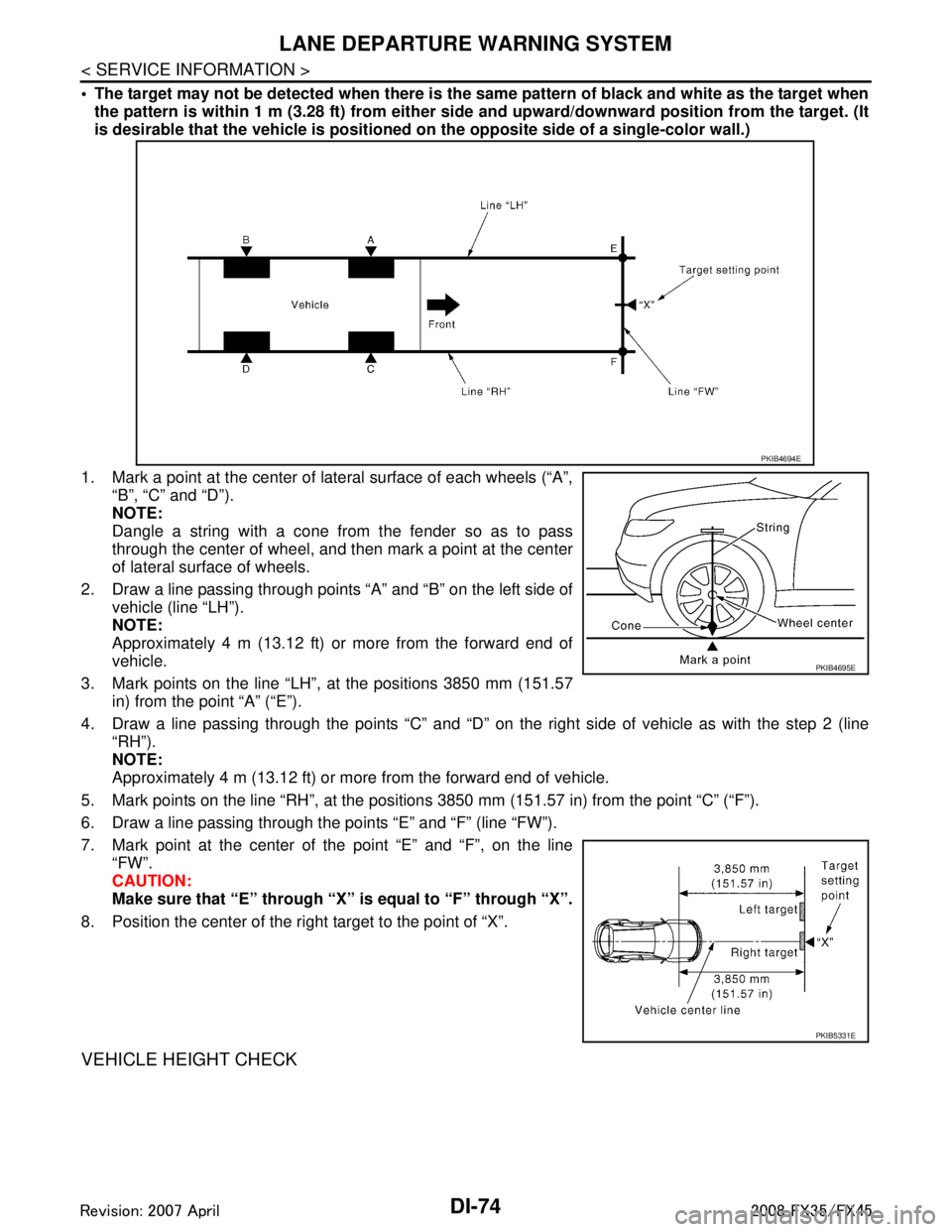
1. Mark a point at the center of lateral surface of each wheels (“A”,
“B”, “C” and “D”).
NOTE:
Dangle a string with a cone from the fender so as to pass
through the center of wheel, and t hen mark a point at the center
of lateral surface of wheels.
2. Draw a line passing through points “A” and “B” on the left side of vehicle (line “LH”).
NOTE:
Approximately 4 m (13.12 ft) or more from the forward end of
vehicle.
3. Mark points on the line “LH”, at the positions 3850 mm (151.57 in) from the point “A” (“E”).
4. Draw a line passing through the points “C” and “D” on t he right side of vehicle as with the step 2 (line
“RH”).
NOTE:
Approximately 4 m (13.12 ft) or more from the forward end of vehicle.
5. Mark points on the line “RH”, at the positions 3850 mm (151.57 in) from the point “C” (“F”).
6. Draw a line passing through the points “E” and “F” (line “FW”).
7. Mark point at the center of the point “E” and “F”, on the line
“FW”.
CAUTION:
Make sure that “E” through “X” is equal to “F” through “X”.
8. Position the center of the right target to the point of “X”.
VEHICLE HEIGHT CHECK
PKIB4694E
PKIB4695E
PKIB5331E
3AA93ABC3ACD3AC03ACA3AC03AC63AC53A913A773A893A873A873A8E3A773A983AC73AC93AC03AC3
3A893A873A873A8F3A773A9D3AAF3A8A3A8C3A863A9D3AAF3A8B3A8C
Page 1201 of 3924

LANE DEPARTURE WARNING SYSTEMDI-75
< SERVICE INFORMATION >
C
DE
F
G H
I
J
L
M A
B
DI
N
O P
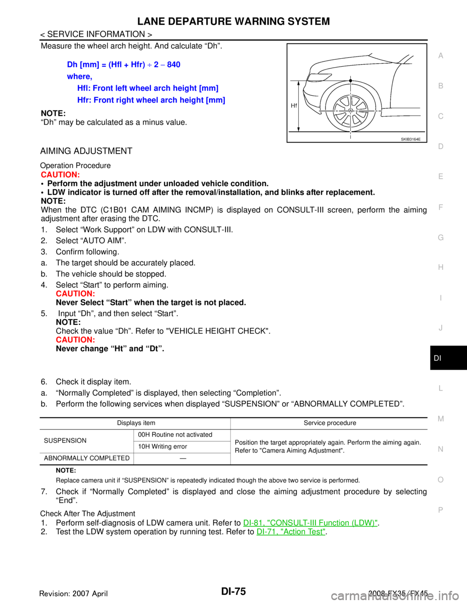
Measure the wheel arch height. And calculate “Dh”.
NOTE:
“Dh” may be calculated as a minus value.
AIMING ADJUSTMENT
Operation Procedure
CAUTION:
Perform the adjustment under unloaded vehicle condition.
LDW indicator is turned off after the remo val/installation, and blinks after replacement.
NOTE:
When the DTC (C1B01 CAM AIMING INCMP) is disp layed on CONSULT-III screen, perform the aiming
adjustment after erasing the DTC.
1. Select “Work Support” on LDW with CONSULT-III.
2. Select “AUTO AIM”.
3. Confirm following.
a. The target should be accurately placed.
b. The vehicle should be stopped.
4. Select “Start” to perform aiming.
CAUTION:
Never Select “Start” when the target is not placed.
5. Input “Dh”, and then select “Start”. NOTE:
Check the value “Dh”. Refer to "VEHICLE HEIGHT CHECK".
CAUTION:
Never change “Ht” and “Dt”.
6. Check it display item.
a. “Normally Completed” is displayed, then selecting “Completion”.
b. Perform the following services when displa yed “SUSPENSION” or “ABNORMALLY COMPLETED”.
NOTE:
Replace camera unit if “SUSPENSION” is repeatedly indicated though the above tw o service is performed.
7. Check if “Normally Completed” is displayed and close the aiming adjustment procedure by selecting
“End”.
Check After The Adjustment
1. Perform self-diagnosis of LDW camera unit. Refer to DI-81, "CONSULT-III Function (LDW)".
2. Test the LDW system operation by running test. Refer to DI-71, "
Action Test".
Dh [mm] = (Hfl + Hfr)
÷ 2 − 840
where, Hfl: Front left wheel arch height [mm]
Hfr: Front right wheel arch height [mm]
SKIB3164E
Displays item Service procedure
SUSPENSION 00H Routine not activated
Position the target appropriately again. Perform the aiming again.
Refer to "Camera Aiming Adjustment".
10H Writing error
ABNORMALLY COMPLETED —
3AA93ABC3ACD3AC03ACA3AC03AC63AC53A913A773A893A873A873A8E3A773A983AC73AC93AC03AC3
3A893A873A873A8F3A773A9D3AAF3A8A3A8C3A863A9D3AAF3A8B3A8C
Page 1210 of 3924

DI-84
< SERVICE INFORMATION >
LANE DEPARTURE WARNING SYSTEM
Preliminary Check
INFOID:0000000001328502
1.CHECK CAMERA LENS AND WINDSHIELD
Are camera lens and windshield contaminated with foreign materials?
YES >> Clean camera lens and windshield.
NO >> GO TO 2.
2.CHECK CAMERA UNIT IN STALLATION CONDITION
Check camera unit installation condition (installat ion position, properly tightened, a bent bracket).
OK or NG
OK >> GO TO 3.
NG >> Install camera unit properly, and adjust camera aiming. Refer to DI-71, "
Camera Aiming Adjust-
ment".
3.CHECK VEHICLE HEIGHT
Check vehicle height. Refer to GI-47, "
Dimensions".
Is vehicle height appropriate?
OK >> GO TO 4.
NG >> Repair vehicle to appropriate height.
4.CHECK LDW CAMERA UNIT (CONSULT-III)
Perform self-diagnosis of LDW camera unit. Refer to DI-81, "
CONSULT-III Function (LDW)".
Self
-diagnosis results
No malfunction detected >> GO TO 5.
Malfunction detected >> Check applicable parts, and repair or replace corresponding parts.
5.CHECK COMBINATION METER
Check combination meter function.
Do speedometer and turn signal indicator normal function?
YES >> INSPECTION END
NO >> Check combination meter. Refer to DI-15, "
Trouble Diagnosis".
Power Supply and Ground Circuit InspectionINFOID:0000000001328503
1.CHECK FUSE
Check for blown LDW camera unit fuse.
Symptom Diagnoses/Service procedure
LDW system is not activated.
(LDW system ON indicator turns ON/OFF.) Perform the following inspections.
1.
DI-86, "
LDW Chime Circuit Inspection"
2.DI-90, "LDW Indicator Lamp Circuit Inspection"
Replace LDW camera unit, check function in the above inspections.
LDW system does not turn ON/OFF.
(LDW system ON indicator does not turn ON/OFF.) Perform
DI-88, "
LDW Switch Circuit Inspection".
Replace LDW camera unit, check function in the above inspection.
Warning functions are untimely. (Example)
Warning does not function when driving on lane markers.
Warning functions when driving in a lane.
Different position from actual condition functions. Perform
DI-71, "
Camera Aiming Adjustment".
Functions when changing the course to the turn signal direction. Perform
DI-91, "
Turn Signal Input Inspection".
Replace LDW camera unit, check function in the above inspection.
LDW indicator lamp does not illuminate with ignition switch ON. Perform
DI-90, "
LDW Indicator Lamp Circuit Inspection".
Replace LDW camera unit, check function in the above inspection.
3AA93ABC3ACD3AC03ACA3AC03AC63AC53A913A773A893A873A873A8E3A773A983AC73AC93AC03AC3
3A893A873A873A8F3A773A9D3AAF3A8A3A8C3A863A9D3AAF3A8B3A8C
Page 1399 of 3924
DTC P0031, P0032, P0051, P0052 A/F SENSOR 1 HEATER
EC-159
< SERVICE INFORMATION > [VQ35DE]
C
D
E
F
G H
I
J
K L
M A
EC
NP
O
Check resistance between terminals 3 and 4.
Check continuity between terminals
3 and 1, 2, 5, 6, terminals 4 and
1, 2, 5, 6.
If NG, replace the air fuel ratio (A/F) sensor 1.
CAUTION:
Discard any air fuel ratio (A/F) sensor which has been dropped from a height of more than 0.5 m (19.7 in) onto a hard
surface such as a concrete floor; use a new one.
Before installing new air fuel ratio (A/F) sensor, clean exhaust
system threads using Heated O xygen Sensor Thread Cleaner
tool J-43897-18 or J-43897-12 and approved anti-seize lubri-
cant.
Removal and InstallationINFOID:0000000001325972
AIR FUEL RATIO (A/F) SENSOR 1
Refer to EM-26.
Resistance: 2.3 - 4.3
Ω [at 25 °C (77 °F)]
Continuity should not exist.
PBIB1684E
3AA93ABC3ACD3AC03ACA3AC03AC63AC53A913A773A893A873A873A8E3A773A983AC73AC93AC03AC3
3A893A873A873A8F3A773A9D3AAF3A8A3A8C3A863A9D3AAF3A8B3A8C
Page 1407 of 3924
DTC P0037, P0038, P0057, P0058 HO2S2 HEATER
EC-167
< SERVICE INFORMATION > [VQ35DE]
C
D
E
F
G H
I
J
K L
M A
EC
NP
O
1. Check resistance between HO2S2 terminals as follows.
2. If NG, replace heated oxygen sensor 2.
CAUTION:
Discard any heated oxygen sen
sor which has been dropped
from a height of more than 0. 5 m (19.7 in) onto a hard surface
such as a concrete floor; use a new one.
Before installing new oxygen sensor, clean exhaust system
threads using Oxygen Sensor Thread Cleaner tool J-43897-18
or J-43897-12 and approved anti-seize lubricant.
Removal and InstallationINFOID:0000000001325980
HEATED OXYGEN SENSOR 2
Refer to EM-26.
Terminal No. Resistance
2 and 3 3.4 - 4.4 Ω [at 25 °C (77 °F)]
1 and 2, 3, 4 ∞ Ω
(Continuity should not exist)
4 and 1, 2, 3
PBIB3344E
3AA93ABC3ACD3AC03ACA3AC03AC63AC53A913A773A893A873A873A8E3A773A983AC73AC93AC03AC3
3A893A873A873A8F3A773A9D3AAF3A8A3A8C3A863A9D3AAF3A8B3A8C
Page 1459 of 3924
![INFINITI FX35 2008 Service Manual
DTC P0130, P0150 A/F SENSOR 1
EC-219
< SERVICE INFORMATION > [VQ35DE]
C
D
E
F
G H
I
J
K L
M A
EC
NP
O
NG >> Repair open circuit or short to ground or short to power in harness or connectors.
5.CHECK INFINITI FX35 2008 Service Manual
DTC P0130, P0150 A/F SENSOR 1
EC-219
< SERVICE INFORMATION > [VQ35DE]
C
D
E
F
G H
I
J
K L
M A
EC
NP
O
NG >> Repair open circuit or short to ground or short to power in harness or connectors.
5.CHECK](/manual-img/42/57017/w960_57017-1458.png)
DTC P0130, P0150 A/F SENSOR 1
EC-219
< SERVICE INFORMATION > [VQ35DE]
C
D
E
F
G H
I
J
K L
M A
EC
NP
O
NG >> Repair open circuit or short to ground or short to power in harness or connectors.
5.CHECK INTERMITTENT INCIDENT
Perform EC-139
.
OK or NG
OK >> GO TO 6.
NG >> Repair or replace.
6.REPLACE AIR FUEL RATIO (A/F) SENSOR 1
Replace malfunctioning air f uel ratio (A/F) sensor 1.
CAUTION:
Discard any air fuel ratio (A/F) sensor which has b een dropped from a height of more than 0.5 m
(19.7 in) onto a hard surface such as a concrete floor; use a new one.
Before installing new air fuel ra tio (A/F) sensor, clean exhaust syst em threads using Heated Oxygen
Sensor Thread Cleaner tool J-43897-18 or J- 43897-12 and approved anti-seize lubricant.
>> INSPECTION END
Removal and InstallationINFOID:0000000001326052
AIR FUEL RATIO (A/F) SENSOR 1
Refer to EM-26.
3AA93ABC3ACD3AC03ACA3AC03AC63AC53A913A773A893A873A873A8E3A773A983AC73AC93AC03AC3
3A893A873A873A8F3A773A9D3AAF3A8A3A8C3A863A9D3AAF3A8B3A8C
Page 1467 of 3924
![INFINITI FX35 2008 Service Manual
DTC P0131, P0151 A/F SENSOR 1
EC-227
< SERVICE INFORMATION > [VQ35DE]
C
D
E
F
G H
I
J
K L
M A
EC
NP
O
NG >> Repair open circuit or short to ground or short to power in harness or connectors.
5.CHECK INFINITI FX35 2008 Service Manual
DTC P0131, P0151 A/F SENSOR 1
EC-227
< SERVICE INFORMATION > [VQ35DE]
C
D
E
F
G H
I
J
K L
M A
EC
NP
O
NG >> Repair open circuit or short to ground or short to power in harness or connectors.
5.CHECK](/manual-img/42/57017/w960_57017-1466.png)
DTC P0131, P0151 A/F SENSOR 1
EC-227
< SERVICE INFORMATION > [VQ35DE]
C
D
E
F
G H
I
J
K L
M A
EC
NP
O
NG >> Repair open circuit or short to ground or short to power in harness or connectors.
5.CHECK INTERMITTENT INCIDENT
Perform EC-139
.
OK or NG
OK >> GO TO 6.
NG >> Repair or replace.
6.REPLACE AIR FUEL RATIO (A/F) SENSOR 1
Replace malfunctioning air f uel ratio (A/F) sensor 1.
CAUTION:
Discard any air fuel ratio (A/F) sensor which has b een dropped from a height of more than 0.5 m
(19.7 in) onto a hard surface such as a concrete floor; use a new one.
Before installing new air fuel ra tio (A/F) sensor, clean exhaust syst em threads using Heated Oxygen
Sensor Thread Cleaner tool J-43897-18 or J- 43897-12 and approved anti-seize lubricant.
>> INSPECTION END
Removal and InstallationINFOID:0000000001326059
AIR FUEL RATIO (A/F) SENSOR 1
Refer to EM-26.
3AA93ABC3ACD3AC03ACA3AC03AC63AC53A913A773A893A873A873A8E3A773A983AC73AC93AC03AC3
3A893A873A873A8F3A773A9D3AAF3A8A3A8C3A863A9D3AAF3A8B3A8C
Page 1475 of 3924
![INFINITI FX35 2008 Service Manual
DTC P0132, P0152 A/F SENSOR 1
EC-235
< SERVICE INFORMATION > [VQ35DE]
C
D
E
F
G H
I
J
K L
M A
EC
NP
O
NG >> Repair open circuit or short to ground or short to power in harness or connectors.
5.CHECK INFINITI FX35 2008 Service Manual
DTC P0132, P0152 A/F SENSOR 1
EC-235
< SERVICE INFORMATION > [VQ35DE]
C
D
E
F
G H
I
J
K L
M A
EC
NP
O
NG >> Repair open circuit or short to ground or short to power in harness or connectors.
5.CHECK](/manual-img/42/57017/w960_57017-1474.png)
DTC P0132, P0152 A/F SENSOR 1
EC-235
< SERVICE INFORMATION > [VQ35DE]
C
D
E
F
G H
I
J
K L
M A
EC
NP
O
NG >> Repair open circuit or short to ground or short to power in harness or connectors.
5.CHECK INTERMITTENT INCIDENT
Perform EC-139
.
OK or NG
OK >> GO TO 6.
NG >> Repair or replace.
6.REPLACE AIR FUEL RATIO (A/F) SENSOR 1
Replace malfunctioning air f uel ratio (A/F) sensor 1.
CAUTION:
Discard any air fuel ratio (A/F) sensor which has b een dropped from a height of more than 0.5 m
(19.7 in) onto a hard surface such as a concrete floor; use a new one.
Before installing new air fuel ra tio (A/F) sensor, clean exhaust syst em threads using Heated Oxygen
Sensor Thread Cleaner tool J-43897-18 or J- 43897-12 and approved anti-seize lubricant.
>> INSPECTION END
Removal and InstallationINFOID:0000000001326066
AIR FUEL RATIO (A/F) SENSOR 1
Refer to EM-26.
3AA93ABC3ACD3AC03ACA3AC03AC63AC53A913A773A893A873A873A8E3A773A983AC73AC93AC03AC3
3A893A873A873A8F3A773A9D3AAF3A8A3A8C3A863A9D3AAF3A8B3A8C