2008 INFINITI FX35 fuel filter
[x] Cancel search: fuel filterPage 2838 of 3924
FL-6
< SERVICE INFORMATION >
FUEL LEVEL SENSOR UNIT, FUEL FILTER AND FUEL PUMP ASSEMBLY
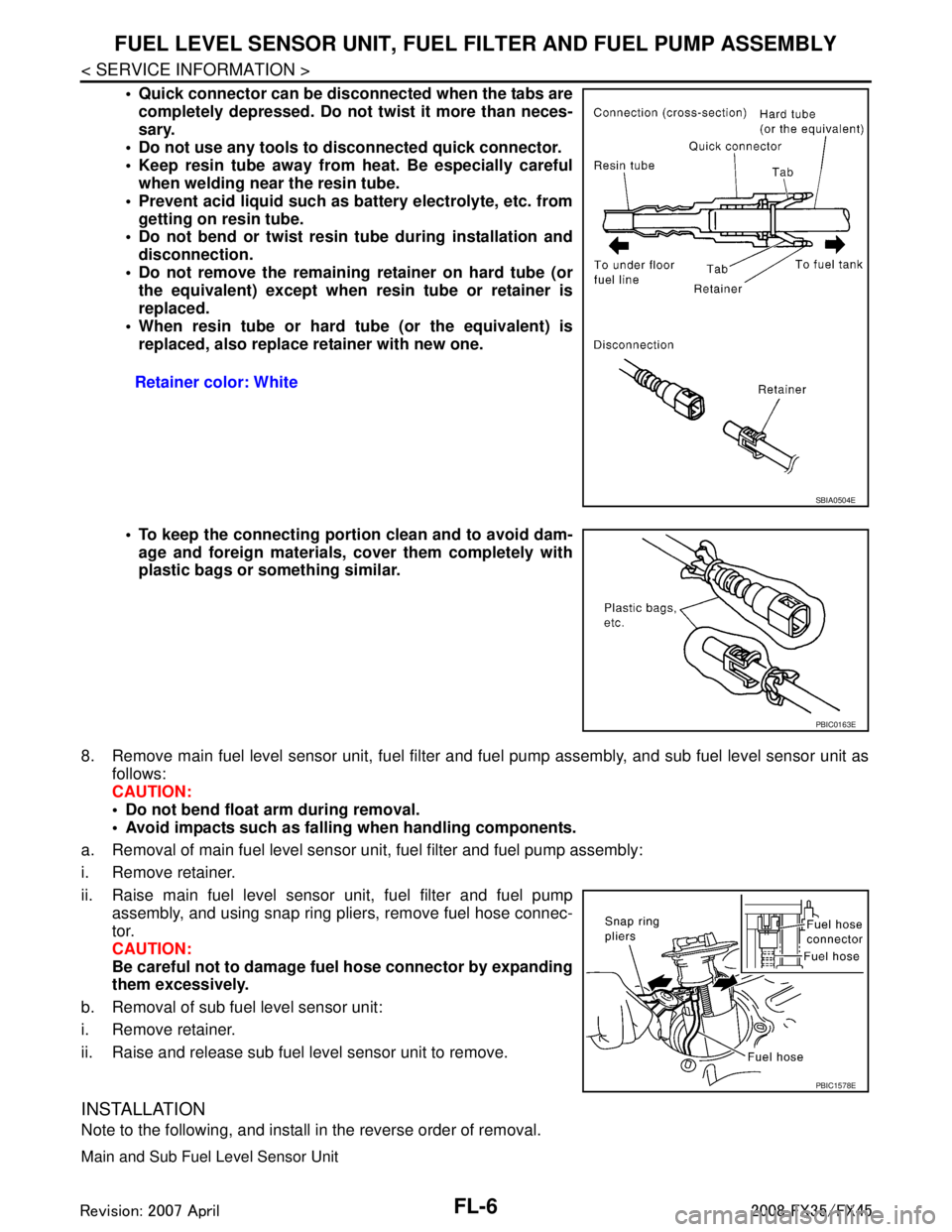
Quick connector can be disconnected when the tabs are
completely depressed. Do not twist it more than neces-
sary.
Do not use any tools to disconnected quick connector.
Keep resin tube away from heat. Be especially careful when welding near the resin tube.
Prevent acid liquid such as battery electrolyte, etc. from getting on resin tube.
Do not bend or twist resin tube during installation and
disconnection.
Do not remove the remaining retainer on hard tube (or the equivalent) except when resin tube or retainer is
replaced.
When resin tube or hard tube (or the equivalent) is replaced, also replace retainer with new one.
To keep the connecting porti on clean and to avoid dam-
age and foreign materials, cover them completely with
plastic bags or something similar.
8. Remove main fuel level sensor unit, fuel filter and fuel pump assembly, and sub fuel level sensor unit as
follows:
CAUTION:
Do not bend float arm during removal.
Avoid impacts such as fallin g when handling components.
a. Removal of main fuel level sensor uni t, fuel filter and fuel pump assembly:
i. Remove retainer.
ii. Raise main fuel level sensor unit, fuel filter and fuel pump assembly, and using snap ring pliers, remove fuel hose connec-
tor.
CAUTION:
Be careful not to damage fu el hose connector by expanding
them excessively.
b. Removal of sub fuel level sensor unit:
i. Remove retainer.
ii. Raise and release sub fuel level sensor unit to remove.
INSTALLATION
Note to the following, and install in the reverse order of removal.
Main and Sub Fuel Level Sensor Unit
Retainer color: White
SBIA0504E
PBIC0163E
PBIC1578E
3AA93ABC3ACD3AC03ACA3AC03AC63AC53A913A773A893A873A873A8E3A773A983AC73AC93AC03AC3
3A893A873A873A8F3A773A9D3AAF3A8A3A8C3A863A9D3AAF3A8B3A8C
Page 2839 of 3924
FUEL LEVEL SENSOR UNIT, FUEL FILTER AND FUEL PUMP ASSEMBLY
FL-7
< SERVICE INFORMATION >
C
D E
F
G H
I
J
K L
M A
FL
NP
O
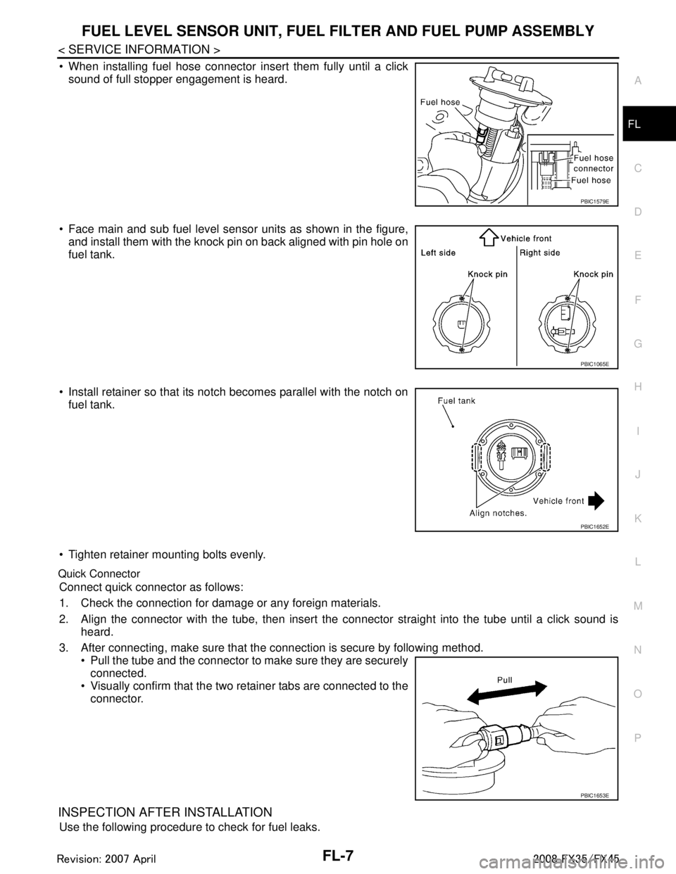
When installing fuel hose connector insert them fully until a click
sound of full stopper engagement is heard.
Face main and sub fuel level sensor units as shown in the figure, and install them with the knock pin on back aligned with pin hole on
fuel tank.
Install retainer so that its notch becomes parallel with the notch on fuel tank.
Tighten retainer mounting bolts evenly.
Quick Connector
Connect quick connector as follows:
1. Check the connection for damage or any foreign materials.
2. Align the connector with the tube, then insert the connector straight into the tube until a click sound is
heard.
3. After connecting, make sure that the connection is secure by following method. Pull the tube and the connector to make sure they are securelyconnected.
Visually confirm that the two retainer tabs are connected to the
connector.
INSPECTION AFTER INSTALLATION
Use the following procedure to check for fuel leaks.
PBIC1579E
PBIC1065E
PBIC1652E
PBIC1653E
3AA93ABC3ACD3AC03ACA3AC03AC63AC53A913A773A893A873A873A8E3A773A983AC73AC93AC03AC3
3A893A873A873A8F3A773A9D3AAF3A8A3A8C3A863A9D3AAF3A8B3A8C
Page 2840 of 3924
FL-8
< SERVICE INFORMATION >
FUEL LEVEL SENSOR UNIT, FUEL FILTER AND FUEL PUMP ASSEMBLY
1. Turn ignition switch “ON” (with engine stopped), then check connections for leaks by applying fuel pres-
sure to fuel piping.
2. Start engine and let it idle and make sure there are no fuel leaks at the fuel system connections.
ComponentINFOID:0000000001327108
Disassembly and AssemblyINFOID:0000000001327109
CAUTION:
Sub fuel level sensor unit cannot be disassembled and should be replaced as a unit.
DISASSEMBLY
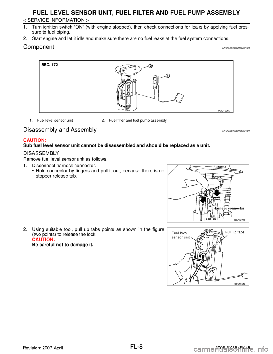
Remove fuel level sensor unit as follows.
1. Disconnect harness connector.
Hold connector by fingers and pull it out, because there is no
stopper release tab.
2. Using suitable tool, pull up tabs points as shown in the figure (two points) to release the lock.
CAUTION:
Be careful not to damage it.
1. Fuel level sensor unit 2. Fuel filter and fuel pump assembly
PBIC1081E
PBIC1078E
PBIC1654E
3AA93ABC3ACD3AC03ACA3AC03AC63AC53A913A773A893A873A873A8E3A773A983AC73AC93AC03AC3
3A893A873A873A8F3A773A9D3AAF3A8A3A8C3A863A9D3AAF3A8B3A8C
Page 2841 of 3924
FUEL LEVEL SENSOR UNIT, FUEL FILTER AND FUEL PUMP ASSEMBLY
FL-9
< SERVICE INFORMATION >
C
D E
F
G H
I
J
K L
M A
FL
NP
O
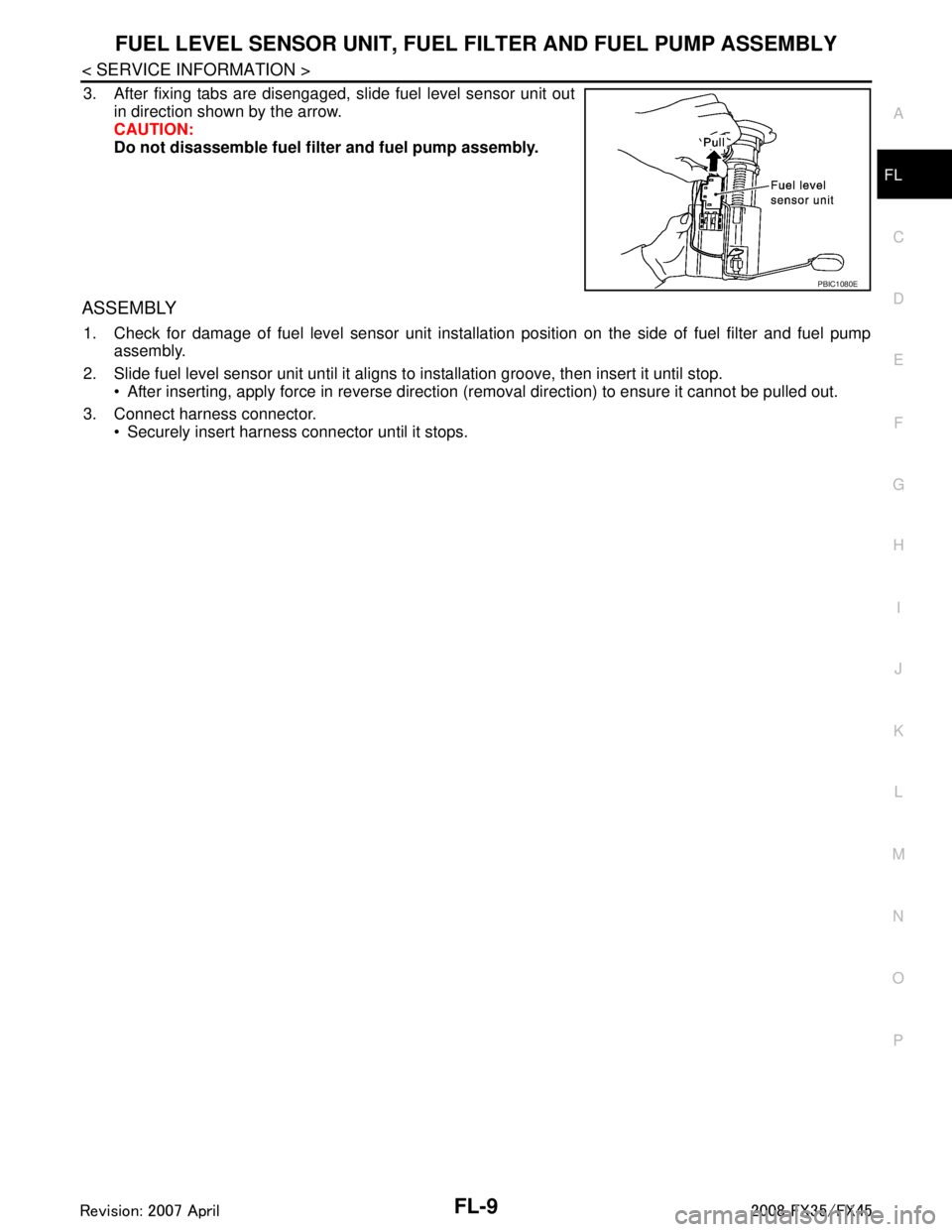
3. After fixing tabs are disengaged, slide fuel level sensor unit out
in direction shown by the arrow.
CAUTION:
Do not disassemble fuel filt er and fuel pump assembly.
ASSEMBLY
1. Check for damage of fuel level sensor unit installa tion position on the side of fuel filter and fuel pump
assembly.
2. Slide fuel level sensor unit until it aligns to installation groove, then insert it until stop. After inserting, apply force in reverse direction (removal direction) to ensure it cannot be pulled out.
3. Connect harness connector. Securely insert harness connector until it stops.
PBIC1080E
3AA93ABC3ACD3AC03ACA3AC03AC63AC53A913A773A893A873A873A8E3A773A983AC73AC93AC03AC3
3A893A873A873A8F3A773A9D3AAF3A8A3A8C3A863A9D3AAF3A8B3A8C
Page 2842 of 3924
FL-10
< SERVICE INFORMATION >
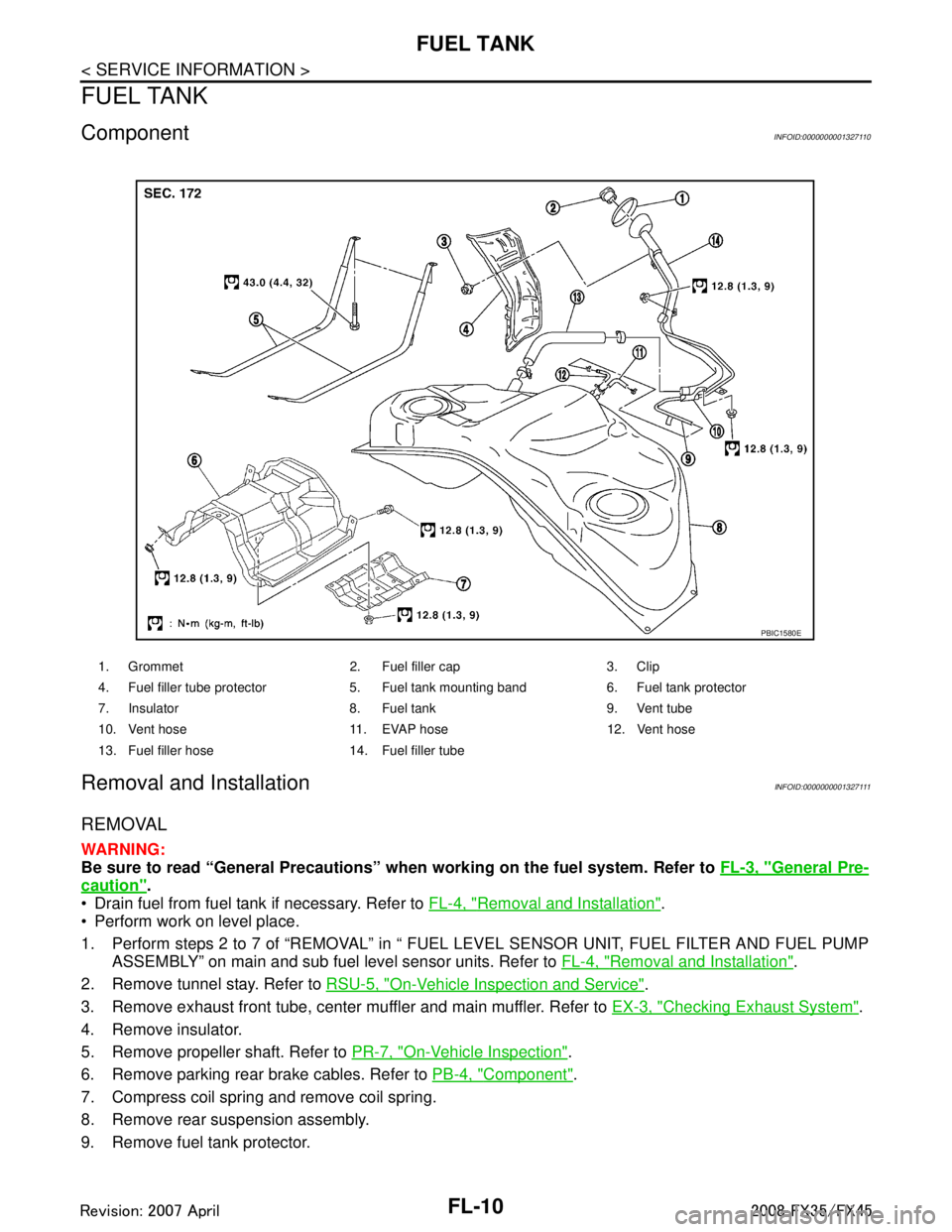
FUEL TANK
FUEL TANK
ComponentINFOID:0000000001327110
Removal and InstallationINFOID:0000000001327111
REMOVAL
WARNING:
Be sure to read “General Precautions” when working on the fuel system. Refer to FL-3, "
General Pre-
caution".
Drain fuel from fuel tank if necessary. Refer to FL-4, "
Removal and Installation".
Perform work on level place.
1. Perform steps 2 to 7 of “REMOVAL” in “ FUEL LEVEL SENSOR UNIT, FUEL FILTER AND FUEL PUMP
ASSEMBLY” on main and sub fuel level sensor units. Refer to FL-4, "
Removal and Installation".
2. Remove tunnel stay. Refer to RSU-5, "
On-Vehicle Inspection and Service".
3. Remove exhaust front tube, center muffler and main muffler. Refer to EX-3, "
Checking Exhaust System".
4. Remove insulator.
5. Remove propeller shaft. Refer to PR-7, "
On-Vehicle Inspection".
6. Remove parking rear brake cables. Refer to PB-4, "
Component".
7. Compress coil spring and remove coil spring.
8. Remove rear suspension assembly.
9. Remove fuel tank protector.
1. Grommet 2. Fuel filler cap 3. Clip
4. Fuel filler tube protector 5. Fuel tank mounting band 6. Fuel tank protector
7. Insulator 8. Fuel tank 9. Vent tube
10. Vent hose 11. EVAP hose 12. Vent hose
13. Fuel filler hose 14. Fuel filler tube
PBIC1580E
3AA93ABC3ACD3AC03ACA3AC03AC63AC53A913A773A893A873A873A8E3A773A983AC73AC93AC03AC3
3A893A873A873A8F3A773A9D3AAF3A8A3A8C3A863A9D3AAF3A8B3A8C
Page 2869 of 3924
PRECAUTIONSGI-7
< SERVICE INFORMATION >
C
DE
F
G H
I
J
K L
M B
GI
N
O P
Heavily soiled clothing and oil-impregnated footwear should not be worn. Overalls must be cleaned regu-
larly.
First aid treatment should be obtai ned immediately for open cuts and wounds.
Use barrier creams, applying them before each work period, to help the removal of oil from the skin.
Wash with soap and water to ensure all oil is removed (skin cleansers and nail brushes will help). Prepara- tions containing lanolin replace the natural skin oils which have been removed.
Do not use gasoline, kerosene, diesel fuel, gas oil, thinners or solvents for cleaning skin.
If skin disorders develop, obtain medical advice without delay.
Where practical, degrease components prior to handling.
Where there is a risk of eye contact, eye protecti on should be worn, for example, chemical goggles or face
shields; in addition an eye wash facility should be provided.
Precaution for the EnvironmentINFOID:0000000001325661
In servicing the vehicle, it may be necessary to use, dispose of or recycle hazardous, flammable, or poisonous
materials, such as gasoline, refrigerant gas, solvents, oil, oil filter, air bag modules, seat belt pretensioners,
etc. Disposal, recycling, and transportation of any haz ardous materials should be performed in compliance
with applicable federal, state and local laws and regulations.
Precaution for Air ConditioningINFOID:0000000001325662
Use an approved refrigerant recovery unit any time t he air conditioning system must be discharged. Refer to
ATC/MTC section “HFC-134a (R-134a) Service Procedure”, “REFRIGERANT LINES” for specific instructions.
3AA93ABC3ACD3AC03ACA3AC03AC63AC53A913A773A893A873A873A8E3A773A983AC73AC93AC03AC3
3A893A873A873A8F3A773A9D3AAF3A8A3A8C3A863A9D3AAF3A8B3A8C
Page 3318 of 3924
MA-1
MAINTENANCE
C
DE
F
G H
I
J
K
M
SECTION MA
A
B
MA
N
O P
CONTENTS
MAINTENANCE
SERVICE INFORMATION .. ..........................2
PREPARATION .............................................. .....2
Special Service Tool ........................................... ......2
Commercial Service Tool ..........................................2
GENERAL MAINTENANCE ................................3
Explanation of General Maintenance .................. ......3
PERIODIC MAINTENANCE ................................5
Introduction of Periodic Maintenance .................. ......5
Schedule 1 ................................................................5
Schedule 2 ................................................................7
RECOMMENDED FLUIDS AND LUBRI-
CANTS .................................................................
9
Fluids and Lubricants .......................................... ......9
Engine Oil Recommendation ....................................9
Anti-Freeze Coolant Mixture Ratio ..........................10
ENGINE MAINTENANCE (VQ35DE ENGINE) ....11
Checking Drive Belts ........................................... ....11
Drive Belts Tension Adjustment ..............................11
Changing Engine Coolant .......................................12
Checking Fuel Line .................................................15
Changing Air Cleaner Filter .....................................15
Changing Engine Oil ...............................................15
Changing Oil Filter ..................................................16
Changing Spark Plugs (Platinum-Tipped Type) ......17
Checking EVAP Vapor Line ....................................18
ENGINE MAINTENANCE (VK45DE ENGINE) ....19
Checking Drive Belts ........................................... ....19
Tension Adjustment ................................................19
Changing Engine Coolant .......................................19
Checking Fuel Line .............................................. ....22
Changing Air Cleaner Filter .....................................22
Changing Engine Oil ................................................22
Changing Oil Filter ...................................................23
Changing Spark Plugs (Platinum-Tipped Type) ......24
Checking EVAP Vapor Line .....................................25
CHASSIS AND BODY MAINTENANCE ...........26
Checking Exhaust System ................................... ....26
Checking A/T Fluid ..................................................26
Changing A/T Fluid ..................................................27
Checking Transfer Fluid ..........................................28
Changing Transfer Fluid ..........................................28
Checking Propeller Shaft .........................................29
Checking Differential Gear Oil .................................29
Changing Differential Gear Oil .................................29
Balancing Wheels (Bonding Weight Type) ..............30
Tire Rotation ............................................................31
Checking Brake Fluid Level and Leaks ...................32
Checking Brake Line and Cables ............................32
Changing Brake Fluid ..............................................32
Checking Disc Brake ...............................................32
Checking Steering Gear and Linkage ......................33
Checking Power Steering Fluid and Line ................33
Axle and Suspension Parts .....................................34
Drive Shaft ...............................................................34
Lubricating Locks, Hinges and Hood Latch .............35
Checking Seat Belt, Buckles, Retractors, Anchors
and Adjusters ...........................................................
35
SERVICE DATA AND SPECIFICATIONS
(SDS) .................................................................
37
Standard and Limit ..................................................37
3AA93ABC3ACD3AC03ACA3AC03AC63AC53A913A773A893A873A873A8E3A773A983AC73AC93AC03AC3
3A893A873A873A8F3A773A9D3AAF3A8A3A8C3A863A9D3AAF3A8B3A8C
Page 3322 of 3924
PERIODIC MAINTENANCEMA-5
< SERVICE INFORMATION >
C
DE
F
G H
I
J
K
M A
B
MA
N
O P
PERIODIC MAINTENANCE
Introduction of Periodic MaintenanceINFOID:0000000001328894
Two different maintenance schedules are provi ded, and should be used, depending upon the conditions in
which the vehicle is mainly operated. After 60,000 miles (96,000 km) or 48 months, continue the periodic
maintenance at the same mileage/time intervals.
Schedule 1INFOID:0000000001328895
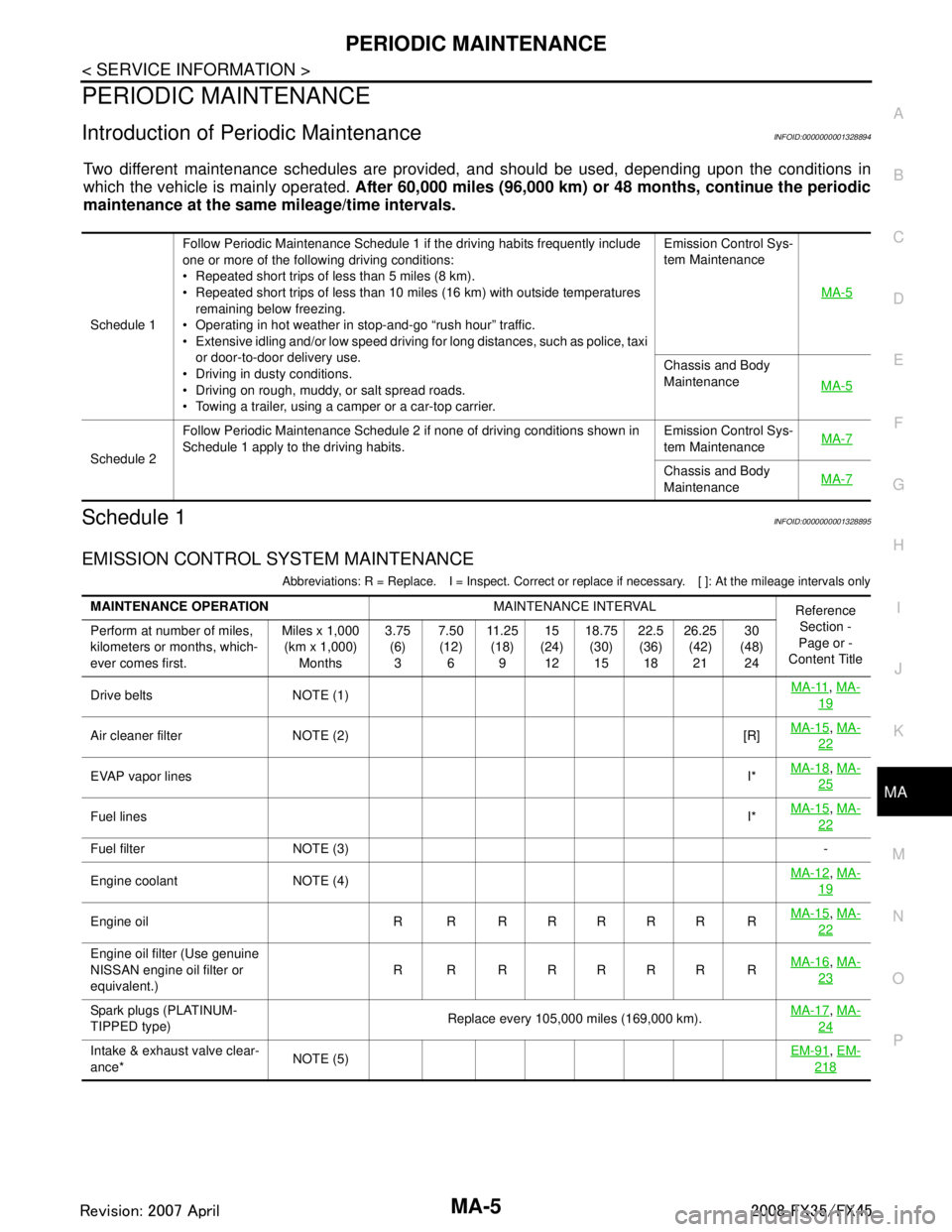
EMISSION CONTROL SYSTEM MAINTENANCE
Abbreviations: R = Replace. I = Inspect. Correct or r eplace if necessary. [ ]: At the mileage intervals only
Schedule 1Follow Periodic Maintenance Schedule 1 if the driving habits frequently include
one or more of the following driving conditions:
Repeated short trips of less than 5 miles (8 km).
Repeated short trips of less than 10 miles (16 km) with outside temperatures
remaining below freezing.
Operating in hot weather in stop-and-go “rush hour” traffic.
Extensive idling and/or low speed driving for long distances, such as police, taxi or door-to-door delivery use.
Driving in dusty conditions.
Driving on rough, muddy, or salt spread roads.
Towing a trailer, using a camper or a car-top carrier. Emission Control Sys-
tem Maintenance
MA-5
Chassis and Body
MaintenanceMA-5
Schedule 2Follow Periodic Maintenance Schedule 2 if none of driving conditions shown in
Schedule 1 apply to the driving habits.
Emission Control Sys-
tem Maintenance
MA-7Chassis and Body
Maintenance
MA-7
MAINTENANCE OPERATION
MAINTENANCE INTERVAL
Reference
Section -
Page or -
Content Title
Perform at number of miles,
kilometers or months, which-
ever comes first. Miles x 1,000
(km x 1,000) Months 3.75
(6)3 7.50
(12) 6 11 . 2 5
(18) 9 15
(24) 12 18.75
(30)15 22.5
(36) 18 26.25
(42)21 30
(48) 24
Drive belts NOTE (1) MA-11
,
MA-
19
Air cleaner filter NOTE (2) [R] MA-15,
MA-
22
EVAP vapor lines I*MA-18,
MA-
25
Fuel lines I*MA-15,
MA-
22
Fuel filter NOTE (3) -
Engine coolant NOTE (4) MA-12
,
MA-
19
Engine oil R R R R R R R R MA-15,
MA-
22
Engine oil filter (Use genuine
NISSAN engine oil filter or
equivalent.) R R RRRRR R
MA-16,
MA-
23
Spark plugs (PLATINUM-
TIPPED type) Replace every 105,000 miles (169,000 km).
MA-17,
MA-
24
Intake & exhaust valve clear-
ance* NOTE (5) EM-91,
EM-
218
3AA93ABC3ACD3AC03ACA3AC03AC63AC53A913A773A893A873A873A8E3A773A983AC73AC93AC03AC3
3A893A873A873A8F3A773A9D3AAF3A8A3A8C3A863A9D3AAF3A8B3A8C