2008 INFINITI FX35 tire size
[x] Cancel search: tire sizePage 3791 of 3924

PRECAUTIONSTF-5
< SERVICE INFORMATION >
CEF
G H
I
J
K L
M A
B
TF
N
O P
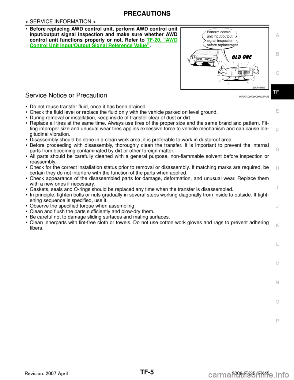
Before replacing AWD control unit, perform AWD control unit
input/output signal inspection and make sure whether AWD
control unit functions properly or not. Refer to TF-20, "
AW D
Control Unit Input/Output Signal Reference Value".
Service Notice or PrecautionINFOID:0000000001327425
Do not reuse transfer fluid, once it has been drained.
Check the fluid level or replace the fluid only with the vehicle parked on level ground.
During removal or installation, keep inside of transfer clear of dust or dirt.
Replace all tires at the same time. Always use tires of the proper size and the same brand and pattern. Fit-
ting improper size and unusual wear tires applies excessive force to vehicle mechanism and can cause lon-
gitudinal vibration.
Disassembly should be done in a clean work area, it is preferable to work in dustproof area.
Before proceeding with disassembly, thoroughly clean the tr ansfer. It is important to prevent the internal
parts from becoming contaminated by dirt or other foreign matter.
All parts should be carefully cleaned with a general purpose, non-flammable solvent before inspection or
reassembly.
Check for the correct installation status prior to remo val or disassembly. If matching marks are required, be
certain they do not interfere with t he function of the parts when applied.
Check appearance of the disassembled parts for dam age, deformation, and unusual wear. Replace them
with a new ones if necessary.
Gaskets, seals and O-rings should be replaced any time when the transfer is disassembled.
In principle, tighten bolts or nuts gradually in several steps working diagonally from inside to outside. If tight-
ening sequence is specified, use it.
Observe the specified torque when assembling.
Clean and flush the parts sufficiently and blow-dry them.
Be careful not to damage sliding surfaces and mating surfaces.
Clean innerparts with lint-free cloth or towels. Do not use cotton work gloves and rags to prevent adhering
fibers.
SDIA1848E
3AA93ABC3ACD3AC03ACA3AC03AC63AC53A913A773A893A873A873A8E3A773A983AC73AC93AC03AC3
3A893A873A873A8F3A773A9D3AAF3A8A3A8C3A863A9D3AAF3A8B3A8C
Page 3806 of 3924

TF-20
< SERVICE INFORMATION >
TROUBLE DIAGNOSIS
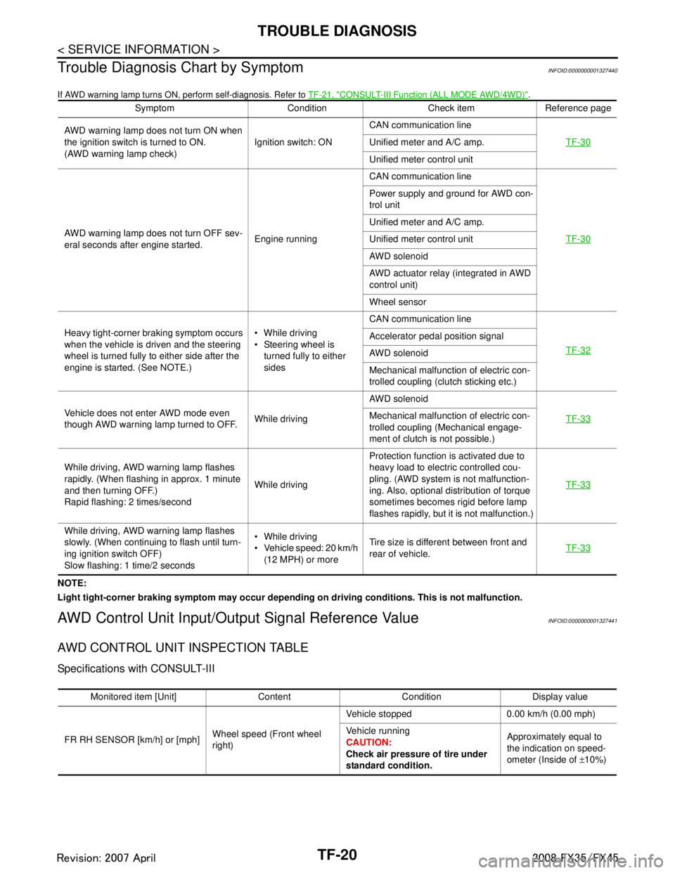
Trouble Diagnosis Chart by Symptom
INFOID:0000000001327440
If AWD warning lamp turns ON, perform self-diagnosis. Refer to TF-21, "CONSULT-III Function (ALL MODE AWD/4WD)".
NOTE:
Light tight-corner braking symptom may occur depending on driving conditions. This is not malfunction.
AWD Control Unit Input/Output Signal Reference ValueINFOID:0000000001327441
AWD CONTROL UNIT INSPECTION TABLE
Specifications with CONSULT-III
Symptom Condition Check item Reference page
AWD warning lamp does not turn ON when
the ignition switch is turned to ON.
(AWD warning lamp check) Ignition switch: ONCAN communication line
TF-30
Unified meter and A/C amp.
Unified meter control unit
AWD warning lamp does not turn OFF sev-
eral seconds after engine started. Engine runningCAN communication line
TF-30
Power supply and ground for AWD con-
trol unit
Unified meter and A/C amp.
Unified meter control unit
AWD solenoid
AWD actuator relay (integrated in AWD
control unit)
Wheel sensor
Heavy tight-corner braking symptom occurs
when the vehicle is driven and the steering
wheel is turned fully to either side after the
engine is started. (See NOTE.) While driving
Steering wheel is
turned fully to either
sides CAN communication line
TF-32
Accelerator pedal position signal
AWD solenoid
Mechanical malfunction of electric con-
trolled coupling (clutch sticking etc.)
Vehicle does not enter AWD mode even
though AWD warning lamp turned to OFF. While drivingAWD solenoid
TF-33
Mechanical malfunction of electric con-
trolled coupling (Mechanical engage-
ment of clutch is not possible.)
While driving, AWD warning lamp flashes
rapidly. (When flashing in approx. 1 minute
and then turning OFF.)
Rapid flashing: 2 times/second While drivingProtection function is activated due to
heavy load to electric controlled cou-
pling. (AWD system is not malfunction-
ing. Also, optional distribution of torque
sometimes becomes rigid before lamp
flashes rapidly, but it is not malfunction.) TF-33
While driving, AWD warning lamp flashes
slowly. (When continuing to flash until turn-
ing ignition switch OFF)
Slow flashing: 1 time/2 seconds While driving
Vehicle speed: 20 km/h
(12 MPH) or more Tire size is different between front and
rear of vehicle.
TF-33
Monitored item [Unit] Content Condition Display value
FR RH SENSOR [km/h] or [mph] Wheel speed (Front wheel
right)Vehicle stopped 0.00 km/h (0.00 mph)
Vehicle running
CAUTION:
Check air pressure of tire under
standard condition.
Approximately equal to
the indication on speed-
ometer (Inside of
±10%)
3AA93ABC3ACD3AC03ACA3AC03AC63AC53A913A773A893A873A873A8E3A773A983AC73AC93AC03AC3
3A893A873A873A8F3A773A9D3AAF3A8A3A8C3A863A9D3AAF3A8B3A8C
Page 3807 of 3924

TROUBLE DIAGNOSISTF-21
< SERVICE INFORMATION >
CEF
G H
I
J
K L
M A
B
TF
N
O P
*: The values are changed by throttle opening and engine speed.
CONSULT-III Function (ALL MODE AWD/4WD)INFOID:0000000001327442
FUNCTION
CONSULT-III can display each diagnostic item using the diagnostic test modes shown following.
FR LH SENSOR [km/h] or [mph] Wheel speed (Front wheel
left)Vehicle stopped 0.00 km/h (0.00 mph)
Vehicle running
CAUTION:
Check air pressure of tire under
standard condition.
Approximately equal to
the indication on speed-
ometer (Inside of
±10%)
RR RH SENSOR [km/h] or [mph] Wheel speed (Rear wheel
right)Vehicle stopped 0.00 km/h (0.00 mph)
Vehicle running
CAUTION:
Check air pressure of tire under
standard condition.
Approximately equal to
the indication on speed-
ometer (Inside of
±10%)
RR LH SENSOR [km/h] or [mph] Wheel speed (Rear wheel left) Vehicle stopped 0.00 km/h (0.00 mph)
Vehicle running
CAUTION:
Check air pressure of tire under
standard condition.Approximately equal to
the indication on speed-
ometer (Inside of
±10%)
BATTERY VOLT [V] Power supply voltage for AWD
control unitIgnition switch: ON Battery voltage
THRTL POS SEN [%] Throttle opening condition When depressing accelerator pedal
(Value rises gradually in response to
throttle position.)0 - 100%
ETS SOLENOID [A] Monitored value of current at
AWD solenoidEngine running
At idle speed
Approx. 0.000A
Engine running
When depressing accelerator ped- al Approx. 0.000 - 2.400A*
STOP LAMP SW [ON/OFF] Condition of brake pedal oper-
ationBrake pedal: Depressed ON
Brake pedal: Released OFF
ENG SPEED SIG [RUN/STOP] Condi tion of engine runningEngine stopped
(Engine speed: Less than 400 rpm)
STOP
Engine running
(Engine speed: 400 rpm or more) RUN
ETS ACTUATOR [ON/OFF] Operating condition of AWD
actuator relay (integrated in
AWD control unit)Engine stopped (Ignition
switch: ON)
OFF
Engine running ON
4WD WARN LAMP [ON/OFF] AWD warning lamp conditionAWD warning lamp: ON ON
AWD warning lamp: OFF OFF
4WD MODE MON [AUTO] Control status of AWD Engine running AUTO
DIS-TIRE MONI [mm] Improper size tire installed
conditionVehicle running with normal size tire
installed
0-4 mm
Vehicle running with improper size
tire installed (Front /rear tire size dif-
ference, wear condition) 4-8 mm, 8- mm
P BRAKE SW [ON/OFF] Condition of parking brake Parking brake operated ON
Parking brake not operated OFF
Monitored item [Unit] Content Condition Display value
3AA93ABC3ACD3AC03ACA3AC03AC63AC53A913A773A893A873A873A8E3A773A983AC73AC93AC03AC3
3A893A873A873A8F3A773A9D3AAF3A8A3A8C3A863A9D3AAF3A8B3A8C
Page 3809 of 3924

TROUBLE DIAGNOSISTF-23
< SERVICE INFORMATION >
CEF
G H
I
J
K L
M A
B
TF
N
O P
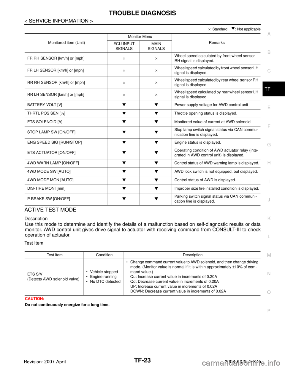
× : Standard : Not applicable
ACTIVE TEST MODE
Description
Use this mode to determine and identify the details of a malfunction based on self-diagnostic results or data
monitor. AWD control unit gives drive signal to actuat or with receiving command from CONSULT-III to check
operation of actuator.
Test Item
CAUTION:
Do not continuously energize for a long time.
Monitored item (Unit) Monitor Menu
Remarks
ECU INPUT
SIGNALS MAIN
SIGNALS
FR RH SENSOR [km/h] or [mph] ××Wheel speed calculated by front wheel sensor
RH signal is displayed.
FR LH SENSOR [km/h] or [mph] ××Wheel speed calculated by front wheel sensor LH
signal is displayed.
RR RH SENSOR [km/h] or [mph] ××Wheel speed calculated by rear wheel sensor RH
signal is displayed.
RR LH SENSOR [km/h] or [mph] ××Wheel speed calculated by rear wheel sensor LH
signal is displayed.
BATTERY VOLT [V] Power supply voltage for AWD control unit
THRTL POS SEN [%] Throttle opening status is displayed.
ETS SOLENOID [A] Monitored value of current at AWD solenoid
STOP LAMP SW [ON/OFF] Stop lamp switch signal status via CAN commu-
nication line is displayed.
ENG SPEED SIG [RUN/STOP] Eng ine status is displayed.
ETS ACTUATOR [ON/OFF] Operating condition of AWD actuator relay (inte-
grated in AWD control unit) is displayed.
4WD WARN LAMP [ON/OFF] Control status of AWD warning lamp is displayed.
4WD MODE SW [AUTO] AWD lock switch is not equipped, but displayed.
4WD MODE MON [AUTO] Control status of AWD is displayed.
DIS-TIRE MONI [mm] Improper size tire installed condition is displayed.
P BRAKE SW [ON/OFF] Parking switch signal status via CAN communi-
cation line is displayed.
Test item Condition Description
ETS S/V
(Detects AWD solenoid valve) Vehicle stopped
Engine running
No DTC detected Change command current value to AWD solenoid, and then change driving
mode. (Monitor value is normal if it is within approximately ±10% of com-
mand value.)
Qu: Increase current value in increments of 0.20A
Qd: Decrease current value in increments of 0.20A
UP: Increase current value in increments of 0.02A
DOWN: Decrease current value in increments of 0.02A
3AA93ABC3ACD3AC03ACA3AC03AC63AC53A913A773A893A873A873A8E3A773A983AC73AC93AC03AC3
3A893A873A873A8F3A773A9D3AAF3A8A3A8C3A863A9D3AAF3A8B3A8C
Page 3820 of 3924

TF-34
< SERVICE INFORMATION >
TROUBLE DIAGNOSIS FOR SYMPTOMS
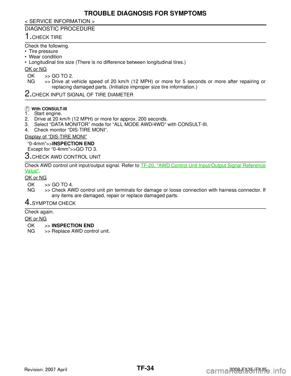
DIAGNOSTIC PROCEDURE
1.CHECK TIRE
Check the following.
Tire pressure
Wear condition
Longitudinal tire size (There is no difference between longitudinal tires.)
OK or NG
OK >> GO TO 2.
NG >> Drive at vehicle speed of 20 km/h (12 MPH) or more for 5 seconds or more after repairing or replacing damaged parts. (Initialize improper size tire information.)
2.CHECK INPUT SIGNAL OF TIRE DIAMETER
With CONSULT-III
1. Start engine.
2. Drive at 20 km/h (12 MPH) or more for approx. 200 seconds.
3. Select “DATA MONITOR” mode for “ALL MODE AWD/4WD” with CONSULT-III.
4. Check monitor “DIS-TIRE MONI”.
Display of
“DIS-TIRE MONI”
“0-4mm”>> INSPECTION END
Except for “0-4mm”>>GO TO 3.
3.CHECK AWD CONTROL UNIT
Check AWD control unit input/output signal. Refer to TF-20, "
AWD Control Unit Input/Output Signal Reference
Va l u e".
OK or NG
OK >> GO TO 4.
NG >> Check AWD control unit pin terminals for dam age or loose connection with harness connector. If
any items are damaged, repair or replace damaged parts.
4.SYMPTOM CHECK
Check again.
OK or NG
OK >> INSPECTION END
NG >> Replace AWD control unit.
3AA93ABC3ACD3AC03ACA3AC03AC63AC53A913A773A893A873A873A8E3A773A983AC73AC93AC03AC3
3A893A873A873A8F3A773A9D3AAF3A8A3A8C3A863A9D3AAF3A8B3A8C
Page 3846 of 3924

WT-6
< SERVICE INFORMATION >
NOISE, VIBRATION AND HARSHNESS (NVH) TROUBLESHOOTING
NOISE, VIBRATION AND HARSHNESS (NVH) TROUBLESHOOTING
NVH Troubleshooting ChartINFOID:0000000001327572
Use the chart below to help you find the cause of the sy mptom. If necessary, repair or replace these parts.
×: Applicable
Reference
FAX-4
,
FAX-11
, FSU-5
WT-7WT-8WT-35WT-9—
—
WT-35
NVH in PR section
NVH in RFD section
NVH in FAX and FSU section
NVH in RAX and RSU section Refer to TIRE in this chart.
Refer to ROAD WHEEL in this chart. NVH in FAX, RAX sectionNVH in BR section
NVH in PS section
Possible cause an d SUSPECTED PARTS
Improper installation, looseness
Out-of-round
Unbalance
Incorrect tire pressure
Uneven tire wear
Deformation or damage
Non-uniformity
Incorrect tire size
PROPELLER SHAFT
DIFFERENTIAL
FRONT AXLE AND FRONT SUSPENSION
REAR AXLE AND REAR SUSPENSION
TIRE
ROAD WHEEL
DRIVE SHAFT
BRAKE
STEERING
SymptomTIRE Noise
× ×××××× ×××× ××××
Shake ××××××××××××××
Vibration ×××××××
Shimmy × ××××××× ×× × ××
Judder ××××××× ×××××
Poor quality ride
or handling × ××××× × ×× ×
ROAD WHEEL Noise
× ×× × ××××× ×××
Shake × ×× × × ××× ×××
Shimmy, Judder ×××× ×××××
Poor quality ride
or handling ××× × ×××
3AA93ABC3ACD3AC03ACA3AC03AC63AC53A913A773A893A873A873A8E3A773A983AC73AC93AC03AC3
3A893A873A873A8F3A773A9D3AAF3A8A3A8C3A863A9D3AAF3A8B3A8C
Page 3875 of 3924

SERVICE DATA AND SPECIFICATIONS (SDS)
WT-35
< SERVICE INFORMATION >
C
D F
G H
I
J
K L
M A
B
WT
N
O P
SERVICE DATA AND SPECIFICATIONS (SDS)
Road WheelINFOID:0000000001327600
TireINFOID:0000000001327601
Unit: kPa (kg/cm2, psi)
Kind of wheel Aluminum Steel (for emergency use)
Maximum radial runout limit Lateral deflection Less than 0.3 mm (0.012 in) Less than 1.5 mm (0.059 in)
Vertical deflection Less than 0.3 mm (0.012 in) Less than 1.5 mm (0.059 in)
Maximum allowable unbalance Dynamic (At rim flange) Less than 5.0 g (0.2 oz) (one side) —
Static (At rim flange) Less than 20 g (0.7 oz) —
Tire size Air pressure
Front Rear
P265/60R18 109V 220 (2.2, 32) 220 (2.2, 32)
P265/50R20 106V 220 (2.2, 32) 220 (2.2, 32)
T175/90D18 110M 420 (4.2, 60) 420 (4.2, 60)
3AA93ABC3ACD3AC03ACA3AC03AC63AC53A913A773A893A873A873A8E3A773A983AC73AC93AC03AC3
3A893A873A873A8F3A773A9D3AAF3A8A3A8C3A863A9D3AAF3A8B3A8C