2008 INFINITI FX35 load capacity
[x] Cancel search: load capacityPage 2157 of 3924
![INFINITI FX35 2008 Service Manual
DTC P0420, P0430 THREE WAY CATALYST FUNCTION
EC-917
< SERVICE INFORMATION > [VK45DE]
C
D
E
F
G H
I
J
K L
M A
EC
NP
O
DTC P0420, P0430 THREE WAY CATALYST FUNCTION
On Board Diagnosis LogicINFOID:000000 INFINITI FX35 2008 Service Manual
DTC P0420, P0430 THREE WAY CATALYST FUNCTION
EC-917
< SERVICE INFORMATION > [VK45DE]
C
D
E
F
G H
I
J
K L
M A
EC
NP
O
DTC P0420, P0430 THREE WAY CATALYST FUNCTION
On Board Diagnosis LogicINFOID:000000](/manual-img/42/57017/w960_57017-2156.png)
DTC P0420, P0430 THREE WAY CATALYST FUNCTION
EC-917
< SERVICE INFORMATION > [VK45DE]
C
D
E
F
G H
I
J
K L
M A
EC
NP
O
DTC P0420, P0430 THREE WAY CATALYST FUNCTION
On Board Diagnosis LogicINFOID:0000000001326754
The ECM monitors the switching frequency ratio of air fuel ratio (A/F)
sensor 1 and heated oxygen sensor 2.
A three way catalyst (manifold) with high oxygen storage capacity
will indicate a low switching frequency of heated oxygen sensor 2.
As oxygen storage capacity decr
eases, the heated oxygen sensor 2
switching frequency will increase.
When the frequency ratio of A/F sensor 1 and heated oxygen sensor
2 approaches a specified limit value, the three way catalyst (mani-
fold) malfunction is diagnosed.
DTC Confirmation ProcedureINFOID:0000000001326755
NOTE:
If DTC Confirmation Procedure has been previously conduc ted, always turn ignition switch OFF and wait at
least 10 seconds before conducting the next test.
WITH CONSULT-III
TESTING CONDITION:
Do not hold engine speed for more than the specified minutes below.
1. Turn ignition switch ON and select “COOLAN TEMP/S” in “DATA MONITOR” mode with CONSULT-III.
2. Start engine and warm it up to the normal operating temperature.
3. Turn ignition switch OFF and wait at least 10 seconds.
4. Start engine and keep the engine speed between 3,500 and 4,000 rpm for at least 1 minute under no load.
5. Let engine idle for 1 minute.
6. Make sure that “COOLAN TEMP/S” indicates more than 70 °C (158 °F).
If not, warm up engine and go to next step when “COOLAN TEMP/S” indication reaches to 70°C (158 °F).
7. Open engine hood.
8. Select “DTC & SRT CONFIRMATION” then “SRT WORK SUPPORT” mode with CONSULT-III.
9. Rev engine up to 2,000 to 3,000 rpm and hold it for 3 consecutive minutes then release the accelerator pedal completely.
If “INCMP” of “CATALYST” changed to “CMPLT”, go to step 12.
10. Wait 5 seconds at idle.
11. Rev engine up to 2,000 to 3,000 rpm and maintain it unt il “INCMP” of “CATALYST” changes to “CMPLT” (It
will take approximately 5 minutes).
If not “CMPLT”, stop engine and cool it down to less than 70 °C (158 °F) and then retest from step 1.
12. Check 1st trip DTC.
13. If the 1st trip DTC is detected, go to EC-918, "
Diagnosis Procedure".
PBIB2055E
DTC No. Trouble diagnosis name DTC detecting condition Possible cause
P0420
0420
(Bank 1) Catalyst system efficien-
cy below threshold Three way catalyst (manifold) does not oper-
ate properly.
Three way catalyst (manifold) does not have enough oxygen storage capacity. Three way catalyst (manifold)
Exhaust tube
Intake air leaks
Fuel injector
Fuel injector leaks
Spark plug
Improper ignition timing
P0430
0430
(Bank 2)
3AA93ABC3ACD3AC03ACA3AC03AC63AC53A913A773A893A873A873A8E3A773A983AC73AC93AC03AC3
3A893A873A873A8F3A773A9D3AAF3A8A3A8C3A863A9D3AAF3A8B3A8C
Page 2608 of 3924
![INFINITI FX35 2008 Service Manual
EM-124
< SERVICE INFORMATION >[VQ35DE]
CYLINDER BLOCK
4. Lift the engine, and mount it onto engine stand (SST).
A widely use engine stand can be used.CAUTION:
Use an engine stand that h as a load c INFINITI FX35 2008 Service Manual
EM-124
< SERVICE INFORMATION >[VQ35DE]
CYLINDER BLOCK
4. Lift the engine, and mount it onto engine stand (SST).
A widely use engine stand can be used.CAUTION:
Use an engine stand that h as a load c](/manual-img/42/57017/w960_57017-2607.png)
EM-124
< SERVICE INFORMATION >[VQ35DE]
CYLINDER BLOCK
4. Lift the engine, and mount it onto engine stand (SST).
A widely use engine stand can be used.CAUTION:
Use an engine stand that h as a load capacity [approxi-
mately 220 kg (485 lb) or more] large enough for support-
ing the engine weight.
NOTE:
This example is an engine stand for holding at transmission
mounting side with drive plate removed.
5. Drain engine oil. Refer to LU-7, "
Changing Engine Oil".
PBIC2685E
PBIC0085E
3AA93ABC3ACD3AC03ACA3AC03AC63AC53A913A773A893A873A873A8E3A773A983AC73AC93AC03AC3
3A893A873A873A8F3A773A9D3AAF3A8A3A8C3A863A9D3AAF3A8B3A8C
Page 2726 of 3924
![INFINITI FX35 2008 Service Manual
EM-242
< SERVICE INFORMATION >[VK45DE]
CYLINDER BLOCK
Refer to
GI-8, "Component" for symbols in the figure.
Disassembly and AssemblyINFOID:0000000001325804
DISASSEMBLY
NOTE:
Explained here is how INFINITI FX35 2008 Service Manual
EM-242
< SERVICE INFORMATION >[VK45DE]
CYLINDER BLOCK
Refer to
GI-8, "Component" for symbols in the figure.
Disassembly and AssemblyINFOID:0000000001325804
DISASSEMBLY
NOTE:
Explained here is how](/manual-img/42/57017/w960_57017-2725.png)
EM-242
< SERVICE INFORMATION >[VK45DE]
CYLINDER BLOCK
Refer to
GI-8, "Component" for symbols in the figure.
Disassembly and AssemblyINFOID:0000000001325804
DISASSEMBLY
NOTE:
Explained here is how to disassemble with engine stand supporting transmission surface. When using differ-
ent type of engine stand, note with difference in steps and etc.
1. Remove engine assembly from vehicle, and separa te front suspension member, transmission and front
final drive from engine. Refer to EM-237, "
Component".
2. Remove the parts that may restrict installation of engine to widely use engine stand. NOTE:
The procedure is described assuming that you use wi dely use engine holding the surface, to which trans-
mission is installed.
a. Remove drive plate. Holding ring gear with ring gear stopper (SST).
Loosen mounting bolts diagonally order.
CAUTION:
Do not disassemble drive plate.
Do not place drive plate with signal plate facing down.
When handling signal plate, take care not to damage or scratch it.
Handle signal plate in a manner that prevents it from becoming magnetized.
b. Remove engine rear plate.
3. Lift engine with hoist to install it onto widely use engine stand. CAUTION:
Use engine stand that has a load capacity [approximately 240 kg ( 529 lb) or more] large enough for
supporting the engine weight.
If the load capacity of stand is not adequate, remo ve the following parts beforehand to reduce the poten-
tial risk of overturning stand.
- Intake manifolds (upper and lower): Refer to EM-175, "
Component".
- Exhaust manifold: Refer to EM-179, "
Component".
- Fuel tube and fuel injector assembly: Refer to EM-190, "
Component".
22. Main bearing 23. Rear plate 24. Crankshaft
25. Pilot converter 26. Drive plate 27. Thrust bearing
28. Side bolt 29. Reinforcement plate 30. Crankshaft position sensor (POS)
31. O-ring 32. Rear oil seal 33. Rear oil seal retainer
A.Refererence: Installed on transmis-
sion B. Refer to
EM-242
C. Right bank
D. Cylinder block heater (For Canada) E. Chamfered F. Crankshaft side : Engine front
PBIC1656E
PBIC2367E
3AA93ABC3ACD3AC03ACA3AC03AC63AC53A913A773A893A873A873A8E3A773A983AC73AC93AC03AC3
3A893A873A873A8F3A773A9D3AAF3A8A3A8C3A863A9D3AAF3A8B3A8C
Page 2830 of 3924

SERVICE DATA AND SPECIFICATIONS (SDS)
FFD-39
< SERVICE INFORMATION >
C EF
G H
I
J
K L
M A
B
FFD
N
O P
SERVICE DATA AND SPECIFICATIONS (SDS)
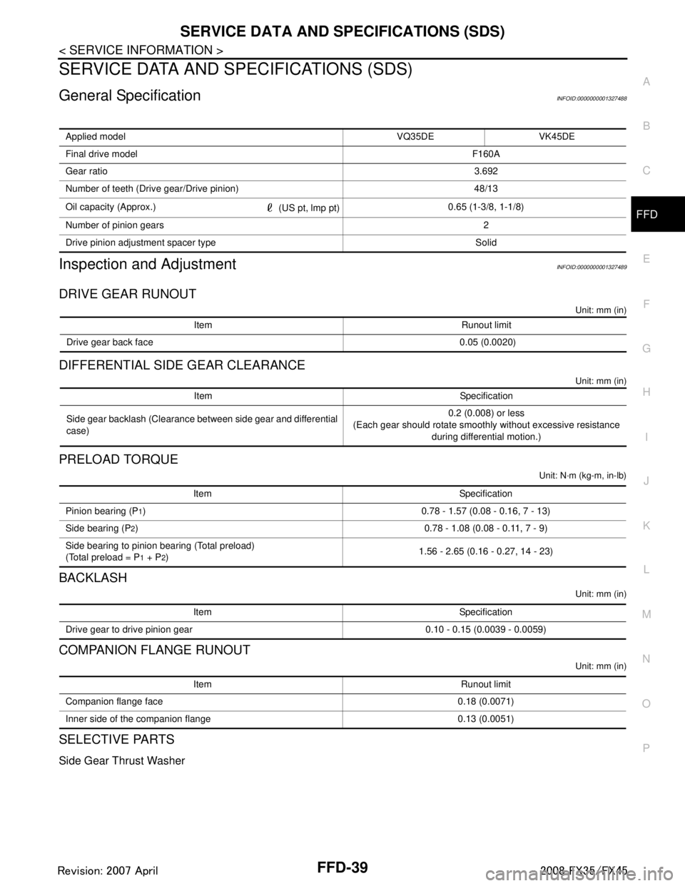
General SpecificationINFOID:0000000001327488
Inspection and AdjustmentINFOID:0000000001327489
DRIVE GEAR RUNOUT
Unit: mm (in)
DIFFERENTIAL SIDE GEAR CLEARANCE
Unit: mm (in)
PRELOAD TORQUE
Unit: N·m (kg-m, in-lb)
BACKLASH
Unit: mm (in)
COMPANION FLANGE RUNOUT
Unit: mm (in)
SELECTIVE PARTS
Side Gear Thrust Washer
Applied model VQ35DE VK45DE
Final drive model F160A
Gear ratio 3.692
Number of teeth (Drive gear/Drive pinion) 48/13
Oil capacity (Approx.) (US pt, lmp pt)0.65 (1-3/8, 1-1/8)
Number of pinion gears 2
Drive pinion adjustment spacer type Solid
Item Runout limit
Drive gear back face 0.05 (0.0020)
Item Specification
Side gear backlash (Clearance between side gear and differential
case) 0.2 (0.008) or less
(Each gear should rotate smoothly without excessive resistance during differential motion.)
Item Specification
Pinion bearing (P
1) 0.78 - 1.57 (0.08 - 0.16, 7 - 13)
Side bearing (P
2) 0.78 - 1.08 (0.08 - 0.11, 7 - 9)
Side bearing to pinion bearing (Total preload)
(Total preload = P
1 + P2) 1.56 - 2.65 (0.16 - 0.27, 14 - 23)
Item Specification
Drive gear to drive pinion gear 0.10 - 0.15 (0.0039 - 0.0059)
Item Runout limit
Companion flange face 0.18 (0.0071)
Inner side of the companion flange 0.13 (0.0051)
3AA93ABC3ACD3AC03ACA3AC03AC63AC53A913A773A893A873A873A8E3A773A983AC73AC93AC03AC3
3A893A873A873A8F3A773A9D3AAF3A8A3A8C3A863A9D3AAF3A8B3A8C
Page 3339 of 3924

MA-22
< SERVICE INFORMATION >
ENGINE MAINTENANCE (VK45DE ENGINE)
5. Rev engine two or three times under no-load.
6. Stop engine and wait until it cools down.
7. Drain water from the system. Refer to "DRAINING ENGINE COOLANT".
8. Repeat steps 1 through 7 until clear water begins to drain from radiator.
Checking Fuel LineINFOID:0000000001328912
Inspect fuel lines, fuel filler cap and fuel tank for improper attach-
ment, leaks, cracks, damage, loose connections, chafing or deterio-
ration.
If necessary, repair or replace damaged parts.
Changing Air Cleaner FilterINFOID:0000000001328913
VISCOUS PAPER TYPE
The viscous paper type filter does not need cleaning between replacement intervals. Refer to MA-5.
1. Remove air duct (inlet), air cleaner case and mass air flow sensor assembly. Refer to EM-173
.
2. Remove air cleaner filter from air cleaner case.
Changing Engine OilINFOID:0000000001328914
WARNING:
Be careful not to burn yoursel f, as engine oil may be hot.
Prolonged and repeated contact with used engine oil may cause ski n cancer. Try to avoid direct skin
contact with used engine oil. If skin contact is made, wash thoroughly with soap or hand cleaner as
soon as possible.
1. Remove front engine undercover with power tool.
2. Warm up engine, put vehicle horizontally and check for engine oil leakage from engine components. Refer
to LU-23, "
Inspection".
3. Stop engine and wait for 15 minutes.
4. Loosen oil filler cap, and then remove drain plug.
5. Drain engine oil.
6. Install drain plug with new washer. Refer to EM-183
.
CAUTION:
Be sure to clean drain plug and install with new washer.
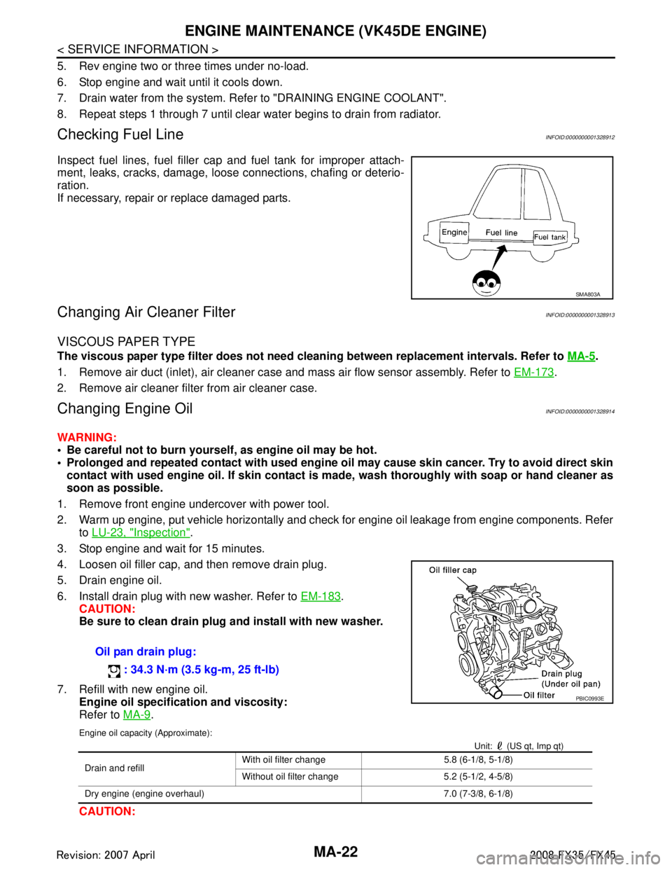
7. Refill with new engine oil. Engine oil specification and viscosity:
Refer to MA-9
.
Engine oil capacity (Approximate):
Unit: (US qt, Imp qt)
CAUTION:
SMA803A
Oil pan drain plug:
: 34.3 N·m (3.5 kg-m, 25 ft-lb)
PBIC0993E
Drain and refill With oil filter change 5.8 (6-1/8, 5-1/8)
Without oil filter change 5.2 (5-1/2, 4-5/8)
Dry engine (engine overhaul) 7.0 (7-3/8, 6-1/8)
3AA93ABC3ACD3AC03ACA3AC03AC63AC53A913A773A893A873A873A8E3A773A983AC73AC93AC03AC3
3A893A873A873A8F3A773A9D3AAF3A8A3A8C3A863A9D3AAF3A8B3A8C
Page 3580 of 3924

RFD-38
< SERVICE INFORMATION >
SERVICE DATA AND SPECIFICATIONS (SDS)
SERVICE DATA AND SPECIFICATIONS (SDS)
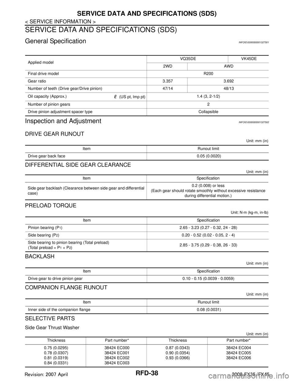
General SpecificationINFOID:0000000001327501
Inspection and AdjustmentINFOID:0000000001327502
DRIVE GEAR RUNOUT
Unit: mm (in)
DIFFERENTIAL SIDE GEAR CLEARANCE
Unit: mm (in)
PRELOAD TORQUE
Unit: N·m (kg-m, in-lb)
BACKLASH
Unit: mm (in)
COMPANION FLANGE RUNOUT
Unit: mm (in)
SELECTIVE PARTS
Side Gear Thrust Washer
Unit: mm (in)
Applied modelVQ35DE VK45DE
2WD AWD
Final drive model R200
Gear ratio 3.357 3.692
Number of teeth (Drive gear/Drive pinion) 47/14 48/13
Oil capacity (Approx.) (US pt, lmp pt)1.4 (3, 2-1/2)
Number of pinion gears 2
Drive pinion adjustment spacer type Collapsible
Item Runout limit
Drive gear back face 0.05 (0.0020)
Item Specification
Side gear backlash (Clearance between side gear and differential
case) 0.2 (0.008) or less
(Each gear should rotate smoothly without excessive resistance
during differential motion.)
Item Specification
Pinion bearing (P
1) 2.65 - 3.23 (0.27 - 0.32, 24 - 28)
Side bearing (P
2) 0.20 - 0.52 (0.02 - 0.05, 2 - 4)
Side bearing to pinion bearing (Total preload)
(Total preload = P
1 + P2) 2.85 - 3.75 (0.29 - 0.38, 26 - 33)
Item Specification
Drive gear to drive pinion gear 0.10 - 0.15 (0.0039 - 0.0059)
Item Runout limit
Inner side of the companion flange 0.08 (0.0031)
Thickness Part number* Thickness Part number*
0.75 (0.0295)
0.78 (0.0307)
0.81 (0.0319)
0.84 (0.0331) 38424 EC000
38424 EC001
38424 EC002
38424 EC003 0.87 (0.0343)
0.90 (0.0354)
0.93 (0.0366)
38424 EC004
38424 EC005
38424 EC006
3AA93ABC3ACD3AC03ACA3AC03AC63AC53A913A773A893A873A873A8E3A773A983AC73AC93AC03AC3
3A893A873A873A8F3A773A9D3AAF3A8A3A8C3A863A9D3AAF3A8B3A8C
Page 3639 of 3924

SC-30
< SERVICE INFORMATION >
SERVICE DATA AND SPECIFICATIONS (SDS)
SERVICE DATA AND SPECIFICATIONS (SDS)
BatteryINFOID:0000000001328260
StarterINFOID:0000000001328261
AlternatorINFOID:0000000001328262
Typ e11 0 D 2 6 L
Capacity V - AH 12 - 75
Cold cranking current (F or reference value) A 720
Applied model VK45DE VQ3 5DE (2WD) VQ35DE (AWD)
Ty p e M002T85075 S114-880A S114-881A
MITSUBISHI make HITACHI make Reduction gear type
System voltage V 12
No-load Te r m i n a l v o l t a g e V 11
Current A Less than 145 Less than 90
Revolution rpm More than 3,300 More than 2,880
Minimum diameter of commutator mm (in) 31.4 (1.236) 28.0 (1.102)
Minimum length of brush mm (in) 11.0 (0.433) 10.5 (0.413)
Brush spring tension N (kg, lb) 26.7 - 36.1
(2.72 - 3.68,
6.80 - 8.12) 16.2 (1.65, 3.6)
Clearance between bearing metal and armature shaft mm (in) Less than 0.2 (0.008)
Clearance between pinion front edge and pinion stopper mm (in) 0.5 - 2.0
(0.020 - 0.079) —
Movement in height of pinion assembly mm (in) — 0.3 - 2.5 (0.012 - 0.098)
Applied model VK45DE VQ35DE
Ty p e LR1110 - 716B A3TG0191
HITACHI make MITSUBISHI make
Nominal rating V - A 12 - 110
Ground polarity Negative
Minimum revolution under no-load (When 13.5 V is applied) rpm Less than 1,100 Less than 1,000
Hot output current (When 13.5 V is applied) A/rpm More than 70/1,800
More than 91/2,500
More than 110/5,000 More than 37/1,300
More than 92/2,500
More than 103/5,000
Regulated output voltage V 14.1 - 14.7
Minimum length of brush mm (in) More than 6.00 (0.236) More than 5.00 (0.197)
Brush spring pressure N (g, oz) 1.00 - 3.43
(102 - 350, 3.60 - 12.34) 4.8 - 6.0
(490 - 612, 17.28 - 21.60)
Slip ring minimum outer diameter mm (in) More than 26.0 (1.024) More than 22.1 (0.870)
Rotor (Field coil) resistance Ω2.31 1.7 - 2.1
3AA93ABC3ACD3AC03ACA3AC03AC63AC53A913A773A893A873A873A8E3A773A983AC73AC93AC03AC3
3A893A873A873A8F3A773A9D3AAF3A8A3A8C3A863A9D3AAF3A8B3A8C