2008 INFINITI FX35 ignition
[x] Cancel search: ignitionPage 3867 of 3924

TROUBLE DIAGNOSESWT-27
< SERVICE INFORMATION >
C
DF
G H
I
J
K L
M A
B
WT
N
O P
Turn signal lamp blinks when ignition
switch is turned on. BCM connector or circuit
BCM
WT-32
ID registration can not be operated.Transmitter
Remote keyless entry receiver connector or circuit
Remote keyless entry receiver
BCM connector or circuit
BCM
WT-32
Code/Symptom Malfunction part Reference
3AA93ABC3ACD3AC03ACA3AC03AC63AC53A913A773A893A873A873A8E3A773A983AC73AC93AC03AC3
3A893A873A873A8F3A773A9D3AAF3A8A3A8C3A863A9D3AAF3A8B3A8C
Page 3870 of 3924
WT-30
< SERVICE INFORMATION >
TROUBLE DIAGNOSIS FOR SYMPTOMS
TROUBLE DIAGNOSIS FOR SYMPTOMS
Low Tire Pressure Warning Lamp Does Not Come On When Ignition Switch Is Turned
On
INFOID:0000000001327593
DIAGNOSTIC PROCEDURE
1.CHECK SELF-DIAGNOSIS RESULTS
1. Select “SELF-DIAG RESULTS” on “SELECT DIAG MODE” screen.
2. Check display contents in self-diagnostic results.
Is
“CAN COMM CIRCUIT” displayed in the self-diagnosis display items?
YES >> Malfunction in CAN communication system. Go to LAN-43, "CAN System Specification Chart".
NO >> No malfunction. GO TO 2.
2.CHECK COMBINATION METER
Check combination meter function.
OK or NG
OK >> GO TO 3.
NG >> Check combination meter. Refer to DI-5, "
System Description".
3.CHECK LOW TIRE PRESSURE WARNING LAMP
Disconnect BCM harness connectors M3 and M4.
Does the warning lamp activate?
YES >> Replace BCM. Refer to BCS-13, "Removal and Installation of BCM".
NO >> Check combination meter and repair or replace.
Low Tire Pressure Warning Lamp Stays On When Ignition Switch Is Turned On
INFOID:0000000001327594
DIAGNOSTIC PROCEDURE
1.CHECK CONNECTOR
1. Disconnect BCM harness connectors M3 and M4.
2. Check terminals for damage or loose connections.
OK or NG
OK >> GO TO 2.
NG >> Repair or replace damaged parts.
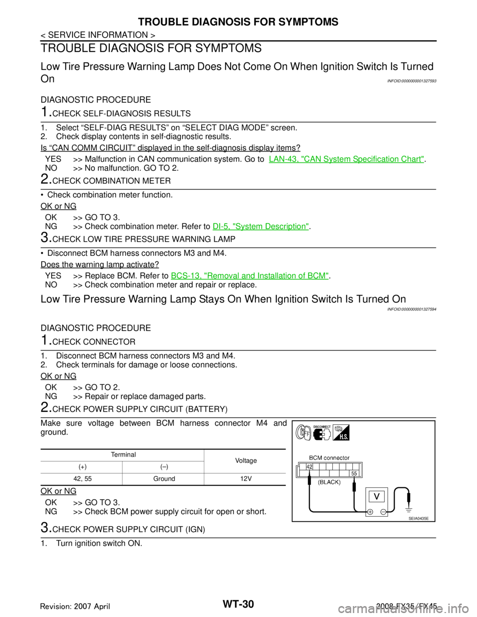
2.CHECK POWER SUPPLY CIRCUIT (BATTERY)
Make sure voltage between BCM harness connector M4 and
ground.
OK or NG
OK >> GO TO 3.
NG >> Check BCM power supply circuit for open or short.
3.CHECK POWER SUPPLY CIRCUIT (IGN)
1. Turn ignition switch ON.
Te r m i n a l Vol tag e
(+) (–)
42, 55 Ground 12V
SEIA0435E
3AA93ABC3ACD3AC03ACA3AC03AC63AC53A913A773A893A873A873A8E3A773A983AC73AC93AC03AC3
3A893A873A873A8F3A773A9D3AAF3A8A3A8C3A863A9D3AAF3A8B3A8C
Page 3871 of 3924
TROUBLE DIAGNOSIS FOR SYMPTOMSWT-31
< SERVICE INFORMATION >
C
DF
G H
I
J
K L
M A
B
WT
N
O P
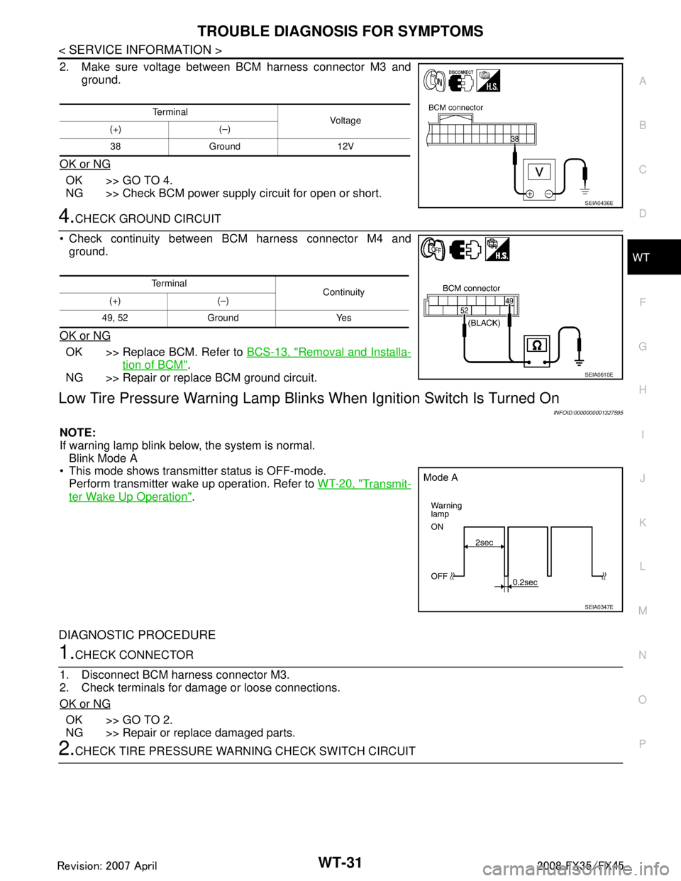
2. Make sure voltage between BCM harness connector M3 and ground.
OK or NG
OK >> GO TO 4.
NG >> Check BCM power supply circuit for open or short.
4.CHECK GROUND CIRCUIT
Check continuity between BCM harness connector M4 and ground.
OK or NG
OK >> Replace BCM. Refer to BCS-13, "Removal and Installa-
tion of BCM".
NG >> Repair or replace BCM ground circuit.
Low Tire Pressure Warning Lamp Blin ks When Ignition Switch Is Turned On
INFOID:0000000001327595
NOTE:
If warning lamp blink below, the system is normal.
Blink Mode A
This mode shows transmitter status is OFF-mode.
Perform transmitter wake up operation. Refer to WT-20, "
Transmit-
ter Wake Up Operation".
DIAGNOSTIC PROCEDURE
1.CHECK CONNECTOR
1. Disconnect BCM harness connector M3.
2. Check terminals for damage or loose connections.
OK or NG
OK >> GO TO 2.
NG >> Repair or replace damaged parts.
2.CHECK TIRE PRESSURE WA RNING CHECK SWITCH CIRCUIT
Te r m i n a l
Voltag e
(+) (–)
38 Ground 12V
SEIA0436E
Te r m i n a l Continuity
(+) (–)
49, 52 Ground Yes
SEIA0610E
SEIA0347E
3AA93ABC3ACD3AC03ACA3AC03AC63AC53A913A773A893A873A873A8E3A773A983AC73AC93AC03AC3
3A893A873A873A8F3A773A9D3AAF3A8A3A8C3A863A9D3AAF3A8B3A8C
Page 3872 of 3924
WT-32
< SERVICE INFORMATION >
TROUBLE DIAGNOSIS FOR SYMPTOMS
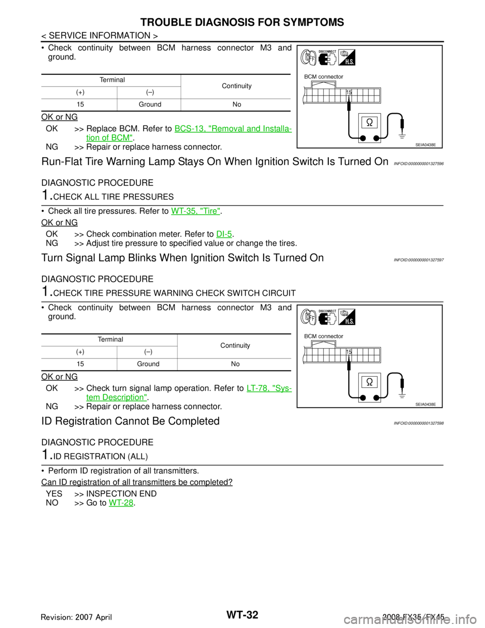
Check continuity between BCM harness connector M3 andground.
OK or NG
OK >> Replace BCM. Refer to BCS-13, "Removal and Installa-
tion of BCM".
NG >> Repair or replace harness connector.
Run-Flat Tire Warning Lamp Stays On When Ignition Switch Is Turned OnINFOID:0000000001327596
DIAGNOSTIC PROCEDURE
1.CHECK ALL TIRE PRESSURES
Check all tire pressures. Refer to WT-35, "
Tire".
OK or NG
OK >> Check combination meter. Refer to DI-5.
NG >> Adjust tire pressure to specified value or change the tires.
Turn Signal Lamp Blinks When Ignition Switch Is Turned OnINFOID:0000000001327597
DIAGNOSTIC PROCEDURE
1.CHECK TIRE PRESSURE WARNI NG CHECK SWITCH CIRCUIT
Check continuity between BCM harness connector M3 and ground.
OK or NG
OK >> Check turn signal lamp operation. Refer to LT-78, "Sys-
tem Description".
NG >> Repair or replace harness connector.
ID Registration Ca nnot Be CompletedINFOID:0000000001327598
DIAGNOSTIC PROCEDURE
1.ID REGISTRATION (ALL)
Perform ID registration of all transmitters.
Can ID registration of all transmitters be completed?
YES >> INSPECTION END
NO >> Go to WT-28
.
Te r m i n a l
Continuity
(+) (–)
15 Ground No
SEIA0438E
Te r m i n a l Continuity
(+) (–)
15 Ground No
SEIA0438E
3AA93ABC3ACD3AC03ACA3AC03AC63AC53A913A773A893A873A873A8E3A773A983AC73AC93AC03AC3
3A893A873A873A8F3A773A9D3AAF3A8A3A8C3A863A9D3AAF3A8B3A8C
Page 3879 of 3924
WW-4
< SERVICE INFORMATION >
FRONT WIPER AND WASHER SYSTEM
FRONT WIPER AND WASHER SYSTEM
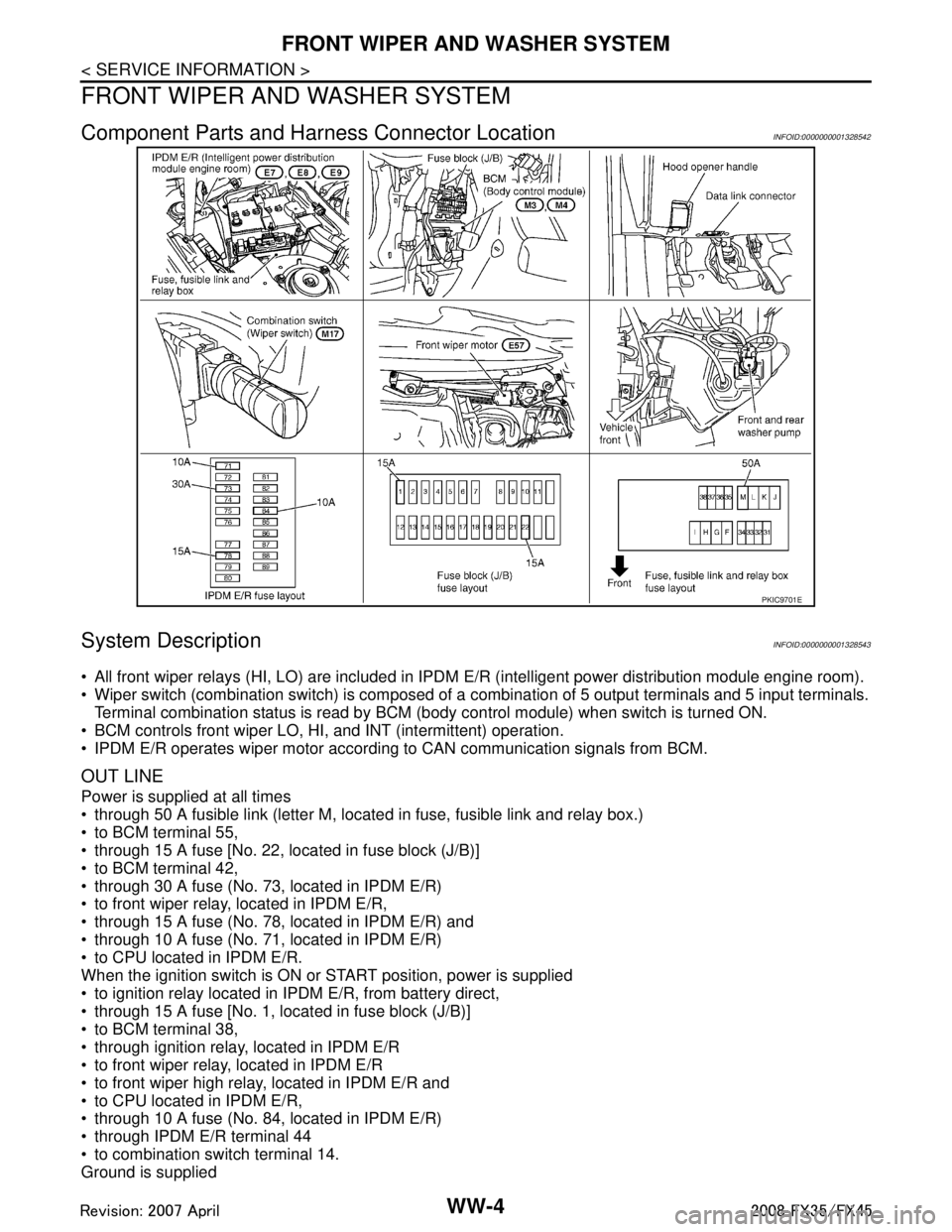
Component Parts and Harness Connector LocationINFOID:0000000001328542
System DescriptionINFOID:0000000001328543
All front wiper relays (HI, LO) are included in IPDM E/R (intelligent power distribution module engine room).
Wiper switch (combination switch) is composed of a combination of 5 output terminals and 5 input terminals.
Terminal combination status is read by BCM ( body control module) when switch is turned ON.
BCM controls front wiper LO, HI, and INT (intermittent) operation.
IPDM E/R operates wiper motor according to CAN communication signals from BCM.
OUT LINE
Power is supplied at all times
through 50 A fusible link (letter M, located in fuse, fusible link and relay box.)
to BCM terminal 55,
through 15 A fuse [No. 22, located in fuse block (J/B)]
to BCM terminal 42,
through 30 A fuse (No. 73, located in IPDM E/R)
to front wiper relay, located in IPDM E/R,
through 15 A fuse (No. 78, located in IPDM E/R) and
through 10 A fuse (No. 71, located in IPDM E/R)
to CPU located in IPDM E/R.
When the ignition switch is ON or START position, power is supplied
to ignition relay located in IPDM E/R, from battery direct,
through 15 A fuse [No. 1, located in fuse block (J/B)]
to BCM terminal 38,
through ignition relay, located in IPDM E/R
to front wiper relay, located in IPDM E/R
to front wiper high relay, located in IPDM E/R and
to CPU located in IPDM E/R,
through 10 A fuse (No. 84, located in IPDM E/R)
through IPDM E/R terminal 44
to combination switch terminal 14.
Ground is supplied
PKIC9701E
3AA93ABC3ACD3AC03ACA3AC03AC63AC53A913A773A893A873A873A8E3A773A983AC73AC93AC03AC3
3A893A873A873A8F3A773A9D3AAF3A8A3A8C3A863A9D3AAF3A8B3A8C
Page 3881 of 3924

WW-6
< SERVICE INFORMATION >
FRONT WIPER AND WASHER SYSTEM
Using combination switch reading function, BCM detects ON/OFF status of INT VOLUME 1, 2, and 3.
When combination switch status is as listed below, BCM det ermines that it is wiper intermittent dial position 1.
INT VOLUME 1: ON (Continuity exists bet ween combination switch output 3 and input 1.)
INT VOLUME 2: ON (Continuity exists bet ween combination switch output 5 and input 1.)
INT VOLUME 3: ON (Continuity exists bet ween combination switch output 4 and input 2.)
BCM determines front wiper intermittent operation delay in terval from wiper intermittent dial position 1 and
vehicle speed, and sends wiper request signal (INT) to IPDM E/R.
AUTO STOP OPERATION
With wiper switch turned OFF, wiper motor will conti nue to operate until wiper arms reach windshield base.
When wiper arms are not located at base of winds hield with wiper switch OFF, ground is provided
from IPDM E/R terminal 21
to front wiper motor terminal 1, in order to continue wiper motor operation at low speed.
When wiper arms reach base of windshield, fr ont wiper motor terminals 5 and 2 are connected,
and Ground is supplied
to IPDM E/R terminal 32
through front wiper motor terminals 5 and 2
through grounds E21, E50 and E51.
Then the IPDM E/R sends auto stop operati on signal to BCM through CAN communication.
When the BCM receives auto-stop operation signal, BCM sends wiper stop signal to IPDM E/R through CAN
communication.
IPDM E/R stops wiper motor. Wiper motor will then stop wiper arms at the STOP position.
WASHER OPERATION
When wiper switch is in front wiper washer position wit h ignition switch on, BCM detects front wiper switch is
on the washer position by BCM wiper switch reading function (Refer to "COMBINATION SWITCH READING
FUNCTION"), combination switch (wiper switch) ground is supplied
to combination switch terminal 13
through front and rear washer pump terminal 1
to front and rear washer pump terminal 2
through combination switch terminal 11
to combination switch terminal 12
through grounds M35, M45 and M85.
With ground supplied, front and rear washer pump is operated.
When BCM detects that front and rear washer pump has operated for 0.4 seconds or linger, BCM operates
front wiper motor for low speed.
When BCM detects washer switch is OFF, low s peed operation cycles approximately 2 times and stops.
MIST OPERATION
When wiper switch is turned to MIST position, wiper low speed operation cycles once and then stops.
For additional information about wiper operation under this condition, Refer to "LOW SPEED WIPER OPERA-
TION".
If switch is held in MIST position, low speed operation continues.
FAIL-SAFE FUNCTION
If an abnormality occurs in CAN communications, IPDM E/ R holds the condition just before fail-safe status is
initiated until ignition switch is turned OFF. (If wipers we re operating in LO just before the initiation of fail-safe
status, they continue to operate in LO until ignition switch is turned OFF.)
COMBINATION SWITCH READING FUNCTION
Refer to BCS-4, "System Description".
CAN Communication System DescriptionINFOID:0000000001328544
CAN (Controller Area Network) is a serial communication line for real time application. It is an on-board multi-
plex communication line with high data communication speed and excellent error detection ability. Many elec-
tronic control units are equipped onto a vehicle, and each control unit shares information and links with other
control units during operation (not independent). In CA N communication, control units are connected with 2
communication lines (CAN H line, CAN L line) allowing a high rate of information transmission with less wiring.
Each control unit transmits/receives data but selectively reads required data only.
3AA93ABC3ACD3AC03ACA3AC03AC63AC53A913A773A893A873A873A8E3A773A983AC73AC93AC03AC3
3A893A873A873A8F3A773A9D3AAF3A8A3A8C3A863A9D3AAF3A8B3A8C
Page 3886 of 3924
FRONT WIPER AND WASHER SYSTEMWW-11
< SERVICE INFORMATION >
C
DE
F
G H
I
J
L
M A
B
WW
N
O P
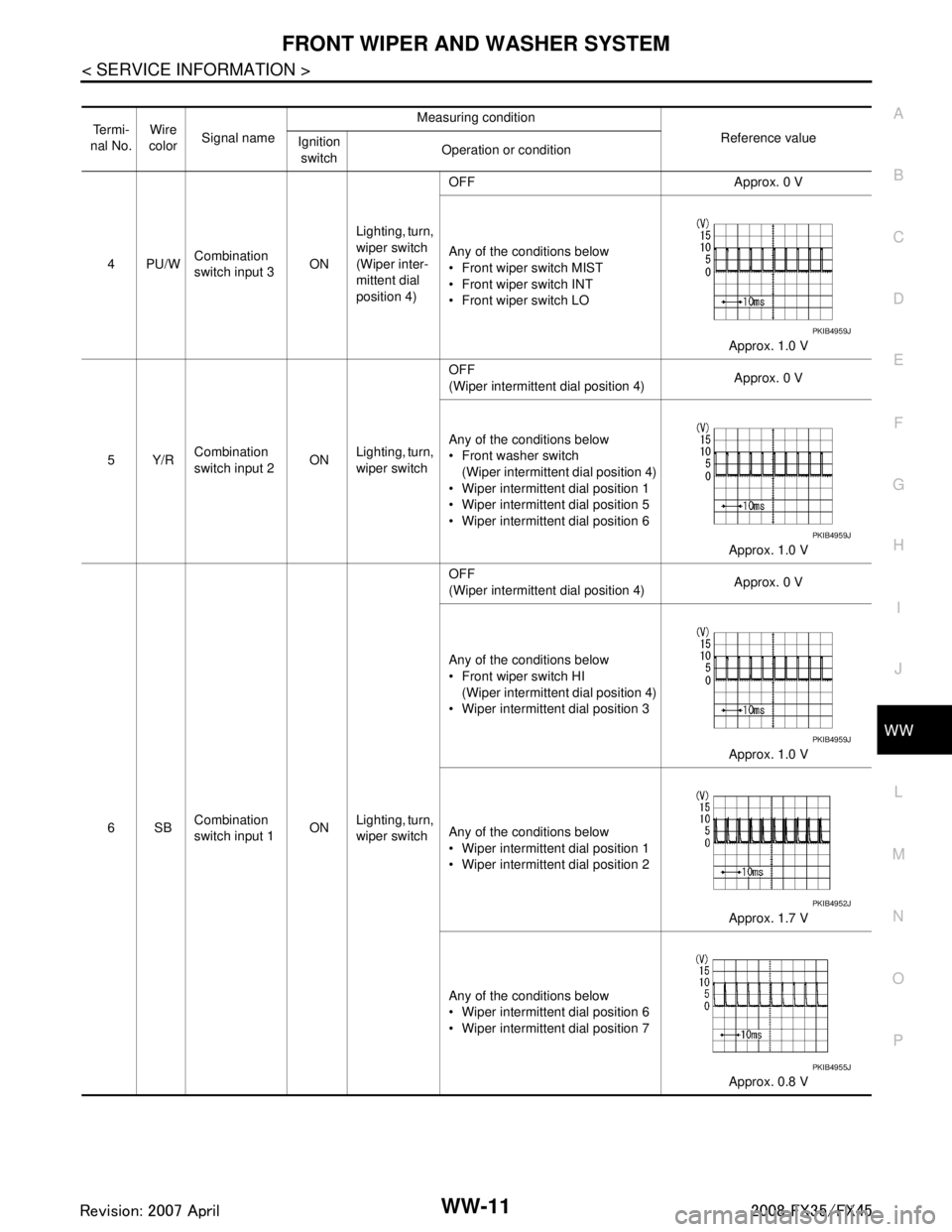
Te r m i -
nal No. Wire
color Signal name Measuring condition
Reference value
Ignition
switch Operation or condition
4PU/W Combination
switch input 3
ONLighting, turn,
wiper switch
(Wiper inter-
mittent dial
position 4) OFF Approx. 0 V
Any of the conditions below
Front wiper switch MIST
Front wiper switch INT
Front wiper switch LO
Approx. 1.0 V
5Y/R Combination
switch input 2 ON
Lighting, turn,
wiper switch OFF
(Wiper intermittent dial position 4)
Approx. 0 V
Any of the conditions below
Front washer switch (Wiper intermittent dial position 4)
Wiper intermittent dial position 1
Wiper intermittent dial position 5
Wiper intermittent dial position 6
Approx. 1.0 V
6SB Combination
switch input 1 ON
Lighting, turn,
wiper switch OFF
(Wiper intermittent dial position 4)
Approx. 0 V
Any of the conditions below
Front wiper switch HI (Wiper intermittent dial position 4)
Wiper intermittent dial position 3
Approx. 1.0 V
Any of the conditions below
Wiper intermittent dial position 1
Wiper intermittent dial position 2 Approx. 1.7 V
Any of the conditions below
Wiper intermittent dial position 6
Wiper intermittent dial position 7 Approx. 0.8 V
PKIB4959J
PKIB4959J
PKIB4959J
PKIB4952J
PKIB4955J
3AA93ABC3ACD3AC03ACA3AC03AC63AC53A913A773A893A873A873A8E3A773A983AC73AC93AC03AC3
3A893A873A873A8F3A773A9D3AAF3A8A3A8C3A863A9D3AAF3A8B3A8C
Page 3887 of 3924
WW-12
< SERVICE INFORMATION >
FRONT WIPER AND WASHER SYSTEM
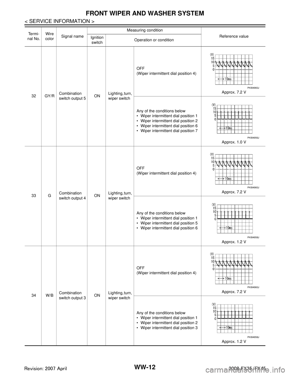
32 GY/RCombination
switch output 5 ON
Lighting, turn,
wiper switch OFF
(Wiper intermittent dial position 4)
Approx. 7.2 V
Any of the conditions below
Wiper intermittent dial position 1
Wiper intermittent dial position 2
Wiper intermittent dial position 6
Wiper intermittent dial position 7 Approx. 1.0 V
33 G Combination
switch output 4
ONLighting, turn,
wiper switch OFF
(Wiper intermittent dial position 4)
Approx. 7.2 V
Any of the conditions below
Wiper intermittent dial position 1
Wiper intermittent dial position 5
Wiper intermittent dial position 6 Approx. 1.2 V
34 W/B Combination
switch output 3 ONLighting, turn,
wiper switch OFF
(Wiper intermittent dial position 4)
Approx. 7.2 V
Any of the conditions below
Wiper intermittent dial position 1
Wiper intermittent dial position 2
Wiper intermittent dial position 3 Approx. 1.2 V
Te r m i -
nal No. Wire
color Signal name Measuring condition
Reference value
Ignition
switch Operation or condition
PKIB4960J
PKIB4956J
PKIB4960J
PKIB4958J
PKIB4960J
PKIB4958J
3AA93ABC3ACD3AC03ACA3AC03AC63AC53A913A773A893A873A873A8E3A773A983AC73AC93AC03AC3
3A893A873A873A8F3A773A9D3AAF3A8A3A8C3A863A9D3AAF3A8B3A8C