2008 INFINITI FX35 coolant temperature
[x] Cancel search: coolant temperaturePage 3321 of 3924
MA-4
< SERVICE INFORMATION >
GENERAL MAINTENANCE
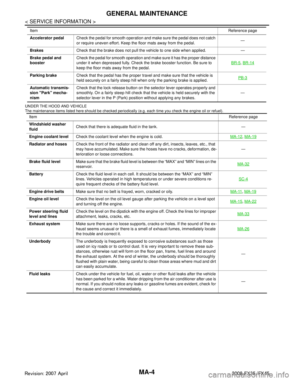
UNDER THE HOOD AND VEHICLE
The maintenance items listed here should be checked periodically (e.g. each time you check the engine oil or refuel).
Accelerator pedalCheck the pedal for smooth operation and make sure the pedal does not catch
or require uneven effort. Keep the floor mats away from the pedal. —
Brakes Check that the brake does not pull the vehicle to one side when applied. —
Brake pedal and
booster Check the pedal for smooth operation and make sure it has the proper distance
under it when depressed fully. Check the brake booster function. Be sure to
keep the floor mats away from the pedal. BR-5
,
BR-14
Parking brake Check that the pedal has the proper travel and make sure that the vehicle is
held securely on a fairly steep hill when only the parking brake is applied. PB-3
Automatic transmis-
sion "Park" mecha-
nismCheck that the lock release button on the selector lever operates properly and
smoothly. On a fairly steep hill check that the vehicle is held securely with the
selector lever in the P (Park) position without applying any brakes.
—
Item
Reference page
Item Reference page
Windshield washer
fluid Check that there is adequate fluid in the tank. —
Engine coolant level Check the coolant level when the engine is cold. MA-12
, MA-19
Radiator and hoses Check the front of the radiator and clean off any dirt, insects, leaves, etc., that
may have accumulated. Make sure the hoses have no cracks, deformation, de-
terioration or loose connections. —
Brake fluid level Make sure that the brake fluid level is between the “MAX” and “MIN” lines on the
reservoir. MA-32
Battery Check the fluid level in each cell. It should be between the “MAX” and “MIN”
lines. Vehicles operated in high temperatures or under severe conditions re-
quire frequent checks of the battery fluid level. SC-4
Engine drive belts
Make sure that no belt is frayed, worn, cracked or oily. MA-11, MA-19
Engine oil level Check the level on the oil level gauge after parking the vehicle on a level spot
and turning off the engine. MA-15,
MA-22
Power steering fluid
level and lines Check the level on the dipstick with the engine off. Check the lines for improper
attachment, leaks, cracks, etc.
MA-33
Exhaust system
Make sure there are no loose supports, cracks or holes. If the sound of the ex-
haust seems unusual or there is a smell of exhaust fumes, immediately locate
the trouble and correct it. MA-26
Underbody
The underbody is frequently exposed to corrosive substances such as those
used on icy roads or to control dust. It is very important to remove these sub-
stances, otherwise rust will form on the floor pan, frame, fuel lines and around
the exhaust system. At the end of winter, the underbody should be thoroughly
flushed with plain water, being careful to clean those areas where mud and dirt
can easily accumulate. —
Fluid leaks Check under the vehicle for fuel, oil, water or other fluid leaks after the vehicle
has been parked for a while. Water dripping from the air conditioner after use is
normal. If you should notice any leaks or gasoline fumes are evident, check for
the cause and correct it immediately. —
3AA93ABC3ACD3AC03ACA3AC03AC63AC53A913A773A893A873A873A8E3A773A983AC73AC93AC03AC3
3A893A873A873A8F3A773A9D3AAF3A8A3A8C3A863A9D3AAF3A8B3A8C
Page 3322 of 3924
PERIODIC MAINTENANCEMA-5
< SERVICE INFORMATION >
C
DE
F
G H
I
J
K
M A
B
MA
N
O P
PERIODIC MAINTENANCE
Introduction of Periodic MaintenanceINFOID:0000000001328894
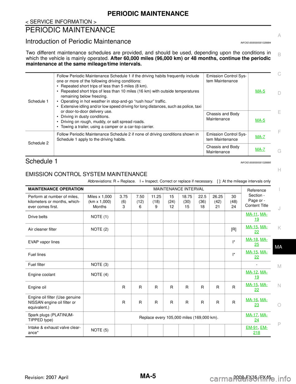
Two different maintenance schedules are provi ded, and should be used, depending upon the conditions in
which the vehicle is mainly operated. After 60,000 miles (96,000 km) or 48 months, continue the periodic
maintenance at the same mileage/time intervals.
Schedule 1INFOID:0000000001328895
EMISSION CONTROL SYSTEM MAINTENANCE
Abbreviations: R = Replace. I = Inspect. Correct or r eplace if necessary. [ ]: At the mileage intervals only
Schedule 1Follow Periodic Maintenance Schedule 1 if the driving habits frequently include
one or more of the following driving conditions:
Repeated short trips of less than 5 miles (8 km).
Repeated short trips of less than 10 miles (16 km) with outside temperatures
remaining below freezing.
Operating in hot weather in stop-and-go “rush hour” traffic.
Extensive idling and/or low speed driving for long distances, such as police, taxi or door-to-door delivery use.
Driving in dusty conditions.
Driving on rough, muddy, or salt spread roads.
Towing a trailer, using a camper or a car-top carrier. Emission Control Sys-
tem Maintenance
MA-5
Chassis and Body
MaintenanceMA-5
Schedule 2Follow Periodic Maintenance Schedule 2 if none of driving conditions shown in
Schedule 1 apply to the driving habits.
Emission Control Sys-
tem Maintenance
MA-7Chassis and Body
Maintenance
MA-7
MAINTENANCE OPERATION
MAINTENANCE INTERVAL
Reference
Section -
Page or -
Content Title
Perform at number of miles,
kilometers or months, which-
ever comes first. Miles x 1,000
(km x 1,000) Months 3.75
(6)3 7.50
(12) 6 11 . 2 5
(18) 9 15
(24) 12 18.75
(30)15 22.5
(36) 18 26.25
(42)21 30
(48) 24
Drive belts NOTE (1) MA-11
,
MA-
19
Air cleaner filter NOTE (2) [R] MA-15,
MA-
22
EVAP vapor lines I*MA-18,
MA-
25
Fuel lines I*MA-15,
MA-
22
Fuel filter NOTE (3) -
Engine coolant NOTE (4) MA-12
,
MA-
19
Engine oil R R R R R R R R MA-15,
MA-
22
Engine oil filter (Use genuine
NISSAN engine oil filter or
equivalent.) R R RRRRR R
MA-16,
MA-
23
Spark plugs (PLATINUM-
TIPPED type) Replace every 105,000 miles (169,000 km).
MA-17,
MA-
24
Intake & exhaust valve clear-
ance* NOTE (5) EM-91,
EM-
218
3AA93ABC3ACD3AC03ACA3AC03AC63AC53A913A773A893A873A873A8E3A773A983AC73AC93AC03AC3
3A893A873A873A8F3A773A9D3AAF3A8A3A8C3A863A9D3AAF3A8B3A8C
Page 3326 of 3924
RECOMMENDED FLUIDS AND LUBRICANTSMA-9
< SERVICE INFORMATION >
C
DE
F
G H
I
J
K
M A
B
MA
N
O P
RECOMMENDED FLUIDS AND LUBRICANTS
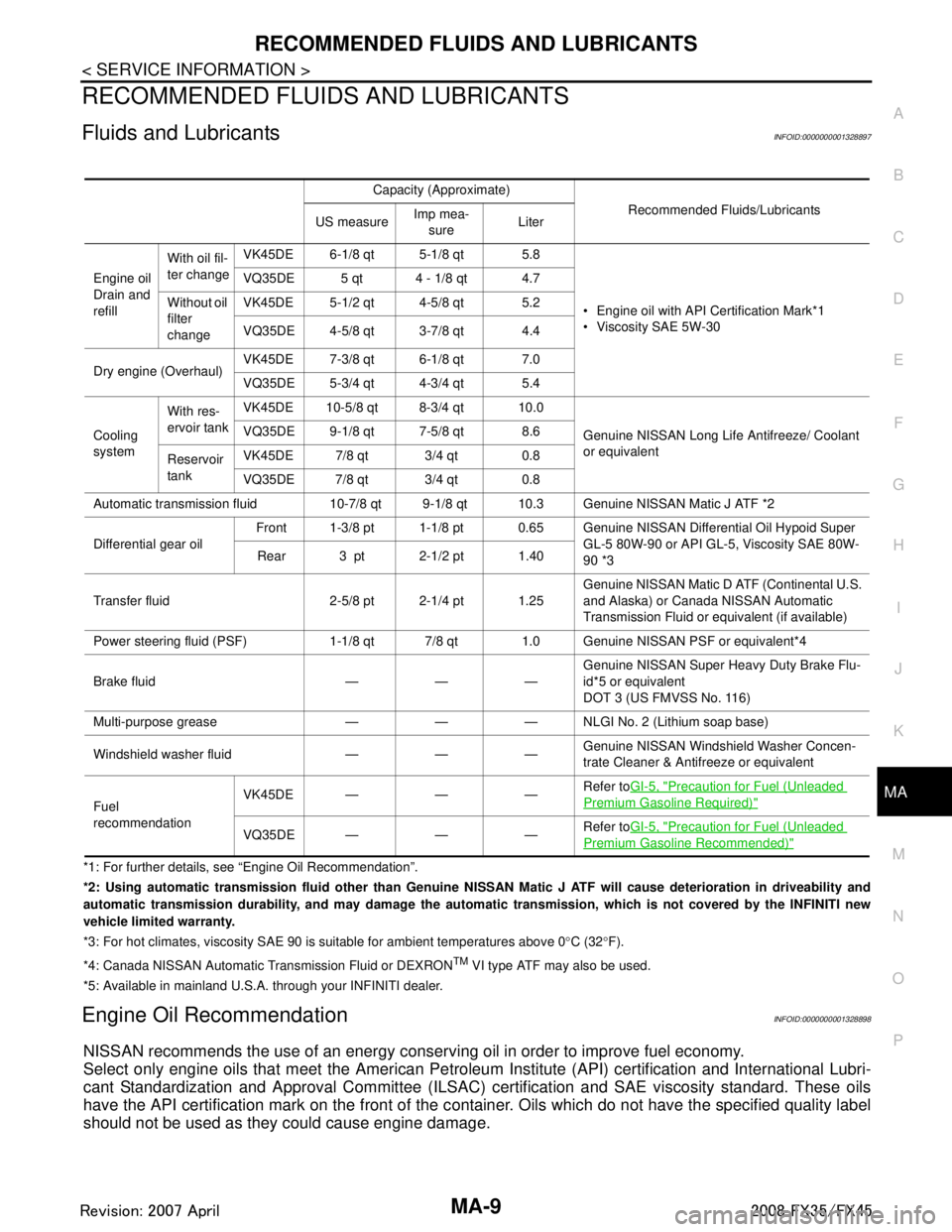
Fluids and LubricantsINFOID:0000000001328897
*1: For further details, see “Engine Oil Recommendation”.
*2: Using automatic transmission fluid other than Genuine NISSAN Matic J ATF will cause deterioration in driveability and
automatic transmission durability, and may damage the automatic transmission, which is not covered by the INFINITI new
vehicle limited warranty.
*3: For hot climates, viscosity SAE 90 is suitable for ambient temperatures above 0 °C (32 °F).
*4: Canada NISSAN Au tomatic Transmission Fluid or DEXRON
TM VI type ATF may also be used.
*5: Available in mainland U.S.A. through your INFINITI dealer.
Engine Oil RecommendationINFOID:0000000001328898
NISSAN recommends the use of an energy conser ving oil in order to improve fuel economy.
Select only engine oils that meet the American Petroleum Institute (API) certification and International Lubri-
cant Standardization and Approval Committee (ILSAC) certification and SAE viscosity standard. These oils
have the API certification mark on the front of the c ontainer. Oils which do not have the specified quality label
should not be used as they could cause engine damage.
Capacity (Approximate)
Recommended Fluids/Lubricants
US measure Imp mea-
sure Liter
Engine oil
Drain and
refill With oil fil-
ter change
VK45DE 6-1/8 qt 5-1/8 qt 5.8
Engine oil with API Certification Mark*1
Viscosity SAE 5W-30
VQ35DE 5 qt 4 - 1/8 qt 4.7
Without oil
filter
change VK45DE 5-1/2 qt 4-5/8 qt 5.2
VQ35DE 4-5/8 qt 3-7/8 qt 4.4
Dry engine (Overhaul) VK45DE 7-3/8 qt 6-1/8 qt 7.0
VQ35DE 5-3/4 qt 4-3/4 qt 5.4
Cooling
system With res-
ervoir tank
VK45DE 10-5/8 qt 8-3/4 qt 10.0
Genuine NISSAN Long Life Antifreeze/ Coolant
or equivalent
VQ35DE 9-1/8 qt 7-5/8 qt 8.6
Reservoir
tank VK45DE 7/8 qt 3/4 qt 0.8
VQ35DE 7/8 qt 3/4 qt 0.8
Automatic transmission fluid 10-7/8 qt 9-1/8 qt 10.3 Genuine NISSAN Matic J ATF *2
Differential gear oil Front 1-3/8 pt 1-1/8 pt 0.65 Genuine NI
SSAN Differential Oil Hypoid Super
GL-5 80W-90 or API GL-5, Viscosity SAE 80W-
90 *3
Rear 3 pt 2-1/2 pt 1.40
Transfer fluid 2-5/8 pt 2-1/4 pt 1.25 Genuine NISSAN Matic D ATF (Continental U.S.
and Alaska) or Canada NISSAN Automatic
Transmission Fluid or equivalent (if available)
Power steering fluid (PSF) 1-1/8 qt 7/8 qt 1.0 Genuine NISSAN PSF or equivalent*4
Brake fluid — — — Genuine NISSAN Super He
avy Duty Brake Flu-
id*5 or equivalent
DOT 3 (US FMVSS No. 116)
Multi-purpose grease — — — NLGI No. 2 (Lithium soap base)
Windshield washer fluid — — — Genuine NISSAN Windshie
ld Washer Concen-
trate Cleaner & Antifreeze or equivalent
Fuel
recommendation VK45DE — — —
Refer to
GI-5, "
Precaution for Fuel (Unleaded
Premium Gasoline Required)"
VQ35DE——— Refer to
GI-5, "Precaution for Fuel (Unleaded
Premium Gasoline Recommended)"
3AA93ABC3ACD3AC03ACA3AC03AC63AC53A913A773A893A873A873A8E3A773A983AC73AC93AC03AC3
3A893A873A873A8F3A773A9D3AAF3A8A3A8C3A863A9D3AAF3A8B3A8C
Page 3331 of 3924
MA-14
< SERVICE INFORMATION >
ENGINE MAINTENANCE (VQ35DE ENGINE)
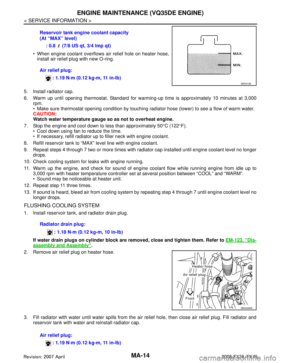
When engine coolant overflows air relief hole on heater hose,install air relief plug with new O-ring.
5. Install radiator cap.
6. Warm up until opening thermostat. Standard for warming- up time is approximately 10 minutes at 3,000
rpm.
Make sure thermostat opening condition by touching radiator hose (lower) to see a flow of warm water.
CAUTION:
Watch water temperature gauge so as not to overheat engine.
7. Stop the engine and cool down to less than approximately 50 °C (122 °F).
Cool down using fan to reduce the time.
If necessary, refill radiator up to filler neck with engine coolant.
8. Refill reservoir tank to “MAX” level line with engine coolant.
9. Repeat steps 4 through 7 two or more times with radiator cap installed until engine coolant level no longer drops.
10. Check cooling system for leaks with engine running.
11. Warm up the engine, and check for sound of engine coolant flow while running engine from idle up to 3,000 rpm with heater temperature controller set at several position between “COOL” and “WARM”.
Sound may be noticeable at heater unit.
12. Repeat step 11 three times.
13. If sound is heard, bleed air from cooling system by repeating step 4 through 7 until engine coolant level no
longer drops.
FLUSHING COOLING SYSTEM
1. Install reservoir tank, and radiator drain plug.
If water drain plugs on cylinder block are removed, close and tighten them. Refer to EM-123, "
Dis-
assembly and Assembly".
2. Remove air relief plug on heater hose.
3. Fill radiator with water until water spills from the ai r relief hole, then close air relief plug. Fill radiator and
reservoir tank with water and reinstall radiator cap. Reservoir tank engine coolant capacity
(At “MAX” level)
: 0.8 (7/8 US qt, 3/4 lmp qt)
Air relief plug: : 1.19 N·m (0.12 kg-m, 11 in-lb)
SMA412B
Radiator drain plug:
: 1.18 N·m (0.12 kg-m, 10 in-lb)
SBIA0445E
Air relief plug: : 1.19 N·m (0.12 kg-m, 11 in-lb)
3AA93ABC3ACD3AC03ACA3AC03AC63AC53A913A773A893A873A873A8E3A773A983AC73AC93AC03AC3
3A893A873A873A8F3A773A9D3AAF3A8A3A8C3A863A9D3AAF3A8B3A8C
Page 3332 of 3924
ENGINE MAINTENANCE (VQ35DE ENGINE)MA-15
< SERVICE INFORMATION >
C
DE
F
G H
I
J
K
M A
B
MA
N
O P
4. Run the engine and warm it up to normal operating temperature.
5. Rev engine two or three times under no-load.
6. Stop the engine and wait until it cools down.
7. Drain water from the system. Refer to CO-10, "
Changing Engine Coolant".
8. Repeat steps 1 through 7 until clear water begins to drain from radiator.
Checking Fuel LineINFOID:0000000001328903
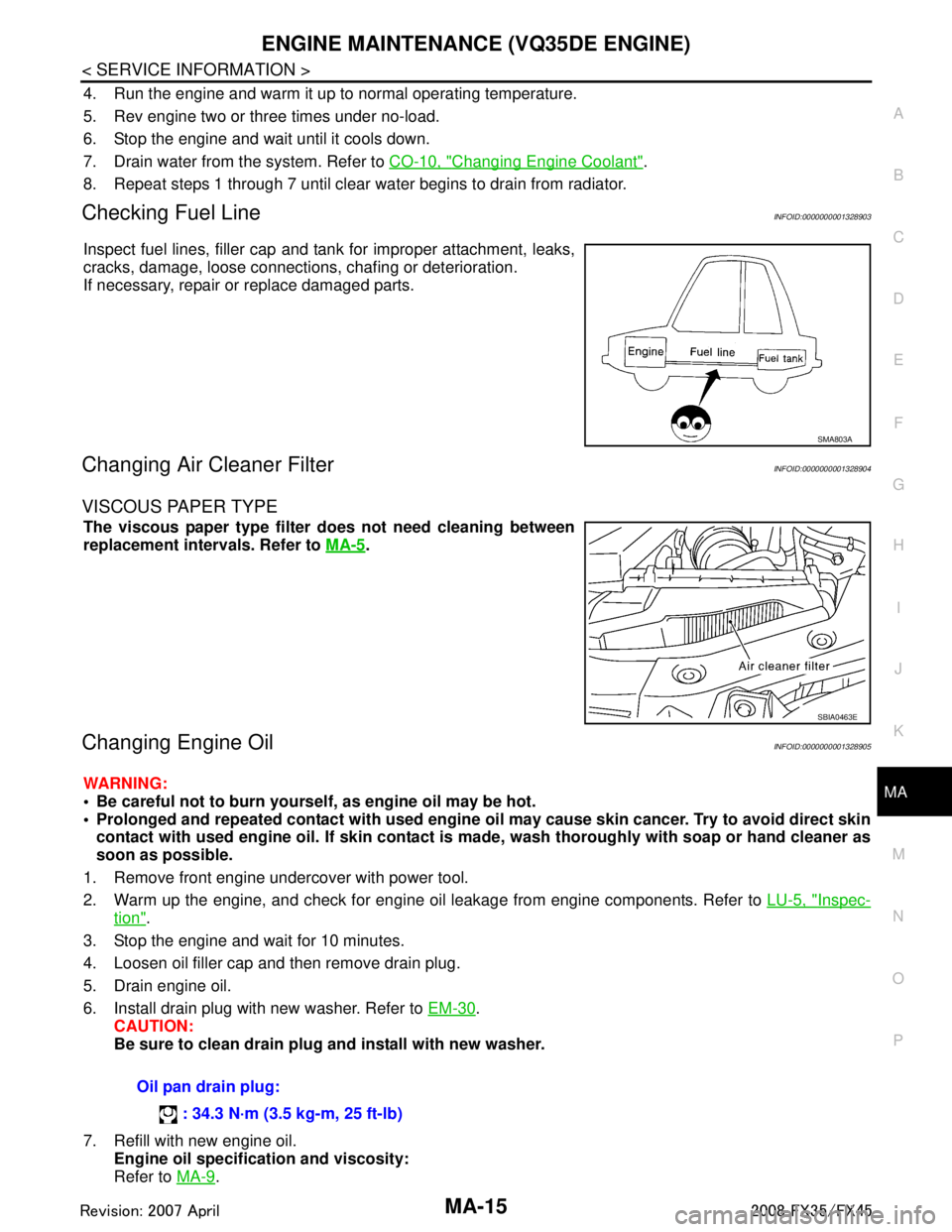
Inspect fuel lines, filler cap and tank for improper attachment, leaks,
cracks, damage, loose connections , chafing or deterioration.
If necessary, repair or replace damaged parts.
Changing Air Cleaner FilterINFOID:0000000001328904
VISCOUS PAPER TYPE
The viscous paper type filter does not need cleaning between
replacement intervals. Refer to MA-5
.
Changing Engine OilINFOID:0000000001328905
WARNING:
Be careful not to burn yoursel f, as engine oil may be hot.
Prolonged and repeated contact with used engine oil may cause skin cancer. Try to avoid direct skin
contact with used engine oil. If skin contact is made, wash thorough ly with soap or hand cleaner as
soon as possible.
1. Remove front engine undercover with power tool.
2. Warm up the engine, and check for engine oil leakage from engine components. Refer to LU-5, "
Inspec-
tion".
3. Stop the engine and wait for 10 minutes.
4. Loosen oil filler cap and then remove drain plug.
5. Drain engine oil.
6. Install drain plug with new washer. Refer to EM-30
.
CAUTION:
Be sure to clean drain plug and install with new washer.
7. Refill with new engine oil. Engine oil specificat ion and viscosity:
Refer to MA-9
.
SMA803A
SBIA0463E
Oil pan drain plug:
: 34.3 N·m (3.5 kg-m, 25 ft-lb)
3AA93ABC3ACD3AC03ACA3AC03AC63AC53A913A773A893A873A873A8E3A773A983AC73AC93AC03AC3
3A893A873A873A8F3A773A9D3AAF3A8A3A8C3A863A9D3AAF3A8B3A8C
Page 3338 of 3924
ENGINE MAINTENANCE (VK45DE ENGINE)MA-21
< SERVICE INFORMATION >
C
DE
F
G H
I
J
K
M A
B
MA
N
O P
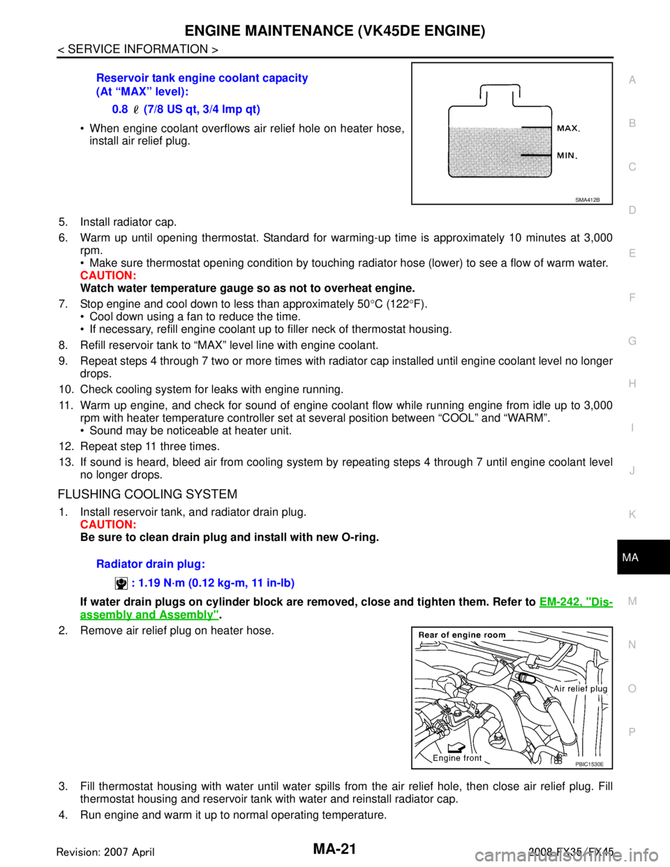
When engine coolant overflows air relief hole on heater hose, install air relief plug.
5. Install radiator cap.
6. Warm up until opening thermostat. Standard for warm ing-up time is approximately 10 minutes at 3,000
rpm.
Make sure thermostat opening condition by touching r adiator hose (lower) to see a flow of warm water.
CAUTION:
Watch water temperature gauge so as not to overheat engine.
7. Stop engine and cool down to less than approximately 50 °C (122 °F).
Cool down using a fan to reduce the time.
If necessary, refill engine coolant up to filler neck of thermostat housing.
8. Refill reservoir tank to “MAX” level line with engine coolant.
9. Repeat steps 4 through 7 two or more times with radiator cap installed until engine coolant level no longer drops.
10. Check cooling system for leaks with engine running.
11. Warm up engine, and check for sound of engine coolant flow while running engine from idle up to 3,000 rpm with heater temperature controller set at several position between “COOL” and “WARM”.
Sound may be noticeable at heater unit.
12. Repeat step 11 three times.
13. If sound is heard, bleed air from cooling system by repeating steps 4 through 7 until engine coolant level
no longer drops.
FLUSHING COOLING SYSTEM
1. Install reservoir tank, and radiator drain plug. CAUTION:
Be sure to clean drain plug and install with new O-ring.
If water drain plugs on cylinder block are removed, close and tighten them. Refer to EM-242, "
Dis-
assembly and Assembly".
2. Remove air relief plug on heater hose.
3. Fill thermostat housing with water until water spills from the air relief hole, then close air relief plug. Fill
thermostat housing and reservoir tank with water and reinstall radiator cap.
4. Run engine and warm it up to normal operating temperature. Reservoir tank engine coolant capacity
(At “MAX” level):
0.8 (7/8 US qt, 3/4 lmp qt)
SMA412B
Radiator drain plug:
: 1.19 N·m (0.12 kg-m, 11 in-lb)
PBIC1530E
3AA93ABC3ACD3AC03ACA3AC03AC63AC53A913A773A893A873A873A8E3A773A983AC73AC93AC03AC3
3A893A873A873A8F3A773A9D3AAF3A8A3A8C3A863A9D3AAF3A8B3A8C
Page 3425 of 3924

HARNESSPG-61
< SERVICE INFORMATION >
C
DE
F
G H
I
J
L
M A
B
PG
N
O P
Code Section Wiring Diagram Name
A/C ATC Air Conditioner
AF1B1 EC Air Fuel Ratio Sensor 1 Bank 1
AF1B2 EC Air Fuel Ratio Sensor 1 Bank 2
AF1HB1 EC Air Fuel Ratio Sensor 1 Heater Bank 1
AF1HB2 EC Air Fuel Ratio Sensor 1 Heater Bank 2
APPS1 EC Accelerator Pedal Position Sensor
APPS2 EC Accelerator Pedal Position Sensor
APPS3 EC Accelerator Pedal Position Sensor
ASC/BS EC Automatic Speed Control Device (ASCD) Brake Switch
ASC/SW EC Automatic Speed Control Device (ASCD) Steering Switch
ASCBOF EC Automatic Speed Control Device (ASCD) Brake Switch
ASCIND EC Automatic Speed Contro l Device (ASCD) Indicator
AT/IND DI A/T Indicator Lamp
AUDIO AV Audio
AUT/DP SE Automatic Drive Positioner
AUTO/L LT Automatic Light System
AWD TF AWD Control System
B/CLOS BL Back Door Closure System
BACK/L LT Back-Up Lamp
BRK/SW EC Brake Switch
CAN AT CAN Communication Line
CAN EC CAN Communication Line
CAN LAN CAN System
CHARGE SC Charging System
CHIME DI Warning Chime
CLOCK DI Clock
COMBSW LT Combination Switch
COMM AV Audio Visual Communication Line
COMPAS DI Compass
COOL/F EC Cooling Fan Control
D/LOCK BL Power Door Lock
DEF GW Rear Window Defogger
DTRL LT Headlamp - With Daytime Light System
ECM/PW EC ECM Power Supply for Back-Up
ECTS EC Engine Coolant Temperature Sensor
ETC1 EC Electric Throttle Control Function
ETC2 EC Electric Throttle Control Motor Relay
ETC3 EC Electric Throttle Control Motor
F/FOG LT Front Fog Lamp
F/PUMP EC Fuel Pump
FTS AT A/T Fluid Temperature Sensor Circuit
FTTS EC Fuel Tank Temperature Sensor
FUELB1 EC Fuel Injection System Function (Bank 1)
FUELB2 EC Fuel Injection System Function (Bank 2)
3AA93ABC3ACD3AC03ACA3AC03AC63AC53A913A773A893A873A873A8E3A773A983AC73AC93AC03AC3
3A893A873A873A8F3A773A9D3AAF3A8A3A8C3A863A9D3AAF3A8B3A8C
Page 3622 of 3924
STARTING SYSTEMSC-13
< SERVICE INFORMATION >
C
DE
F
G H
I
J
L
M A
B
SC
N
O P
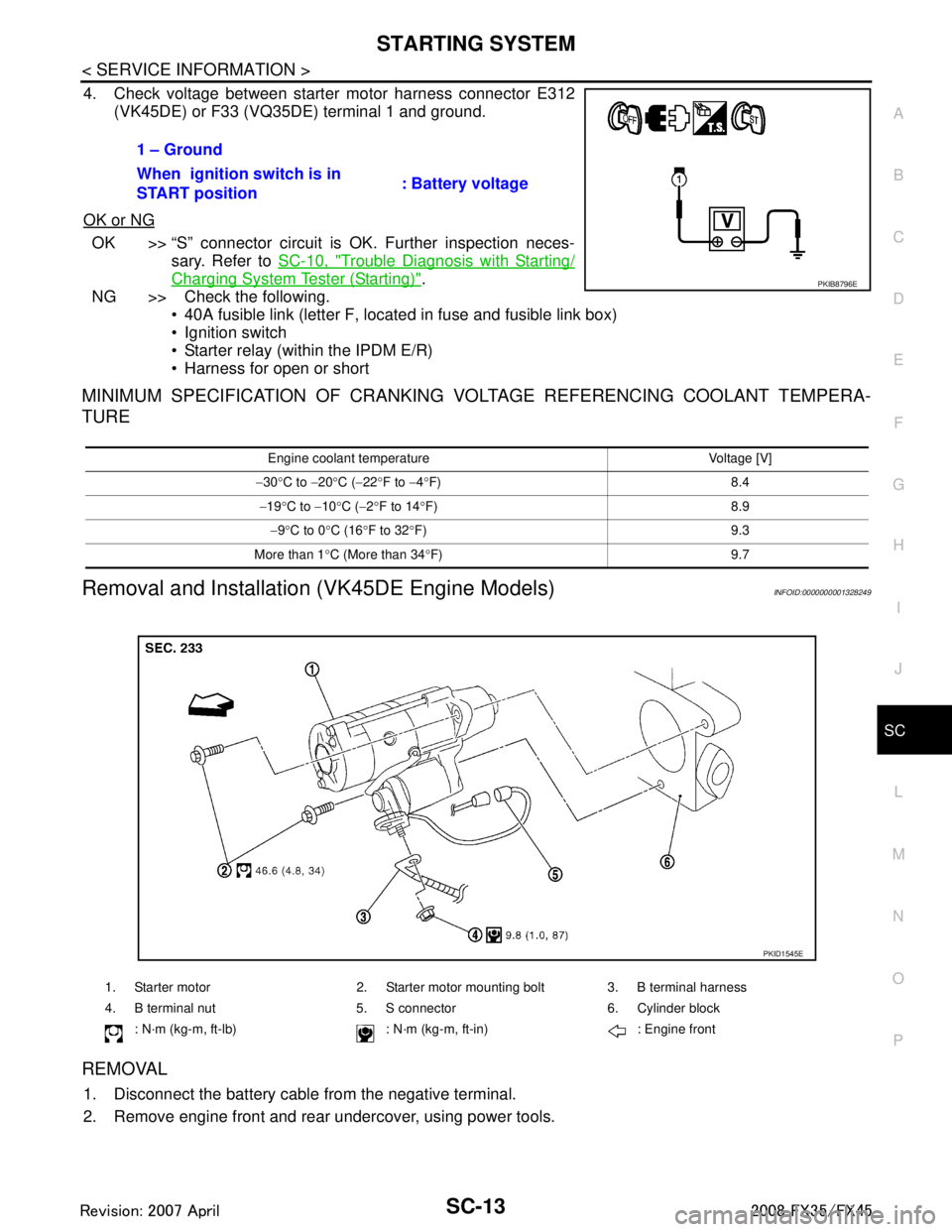
4. Check voltage between starter motor harness connector E312 (VK45DE) or F33 (VQ35DE) terminal 1 and ground.
OK or NG
OK >> “S” connector circuit is OK. Further inspection neces- sary. Refer to SC-10, "
Trouble Diagnosis with Starting/
Charging System Tester (Starting)".
NG >> Check the following.
40A fusible link (letter F, located in fuse and fusible link box)
Ignition switch
Starter relay (within the IPDM E/R)
Harness for open or short
MINIMUM SPECIFICATION OF CRANKING VO LTAGE REFERENCING COOLANT TEMPERA-
TURE
Removal and Installation (VK45DE Engine Models)INFOID:0000000001328249
REMOVAL
1. Disconnect the battery cable from the negative terminal.
2. Remove engine front and rear undercover, using power tools. 1 – Ground
When ignition switch is in
START position
: Battery voltage
PKIB8796E
Engine coolant temperature Voltage [V]
− 30 °C to −20 °C ( −22 °F to −4 °F) 8.4
− 19 °C to −10 °C ( −2 °F to 14 °F) 8.9
− 9 °C to 0 °C (16 °F to 32 °F) 9.3
More than 1 °C (More than 34 °F) 9.7
1. Starter motor 2. Starter motor mounting bolt 3. B terminal harness
4. B terminal nut 5. S connector 6. Cylinder block
: N·m (kg-m, ft-lb) : N·m (k g-m, ft-in) : Engine front
PKID1545E
3AA93ABC3ACD3AC03ACA3AC03AC63AC53A913A773A893A873A873A8E3A773A983AC73AC93AC03AC3
3A893A873A873A8F3A773A9D3AAF3A8A3A8C3A863A9D3AAF3A8B3A8C