2008 INFINITI FX35 ignition switch
[x] Cancel search: ignition switchPage 3714 of 3924
AUTOMATIC DRIVE POSITIONERSE-75
< SERVICE INFORMATION >
C
DE
F
G H
J
K L
M A
B
SE
N
O P
With CONSULT-III
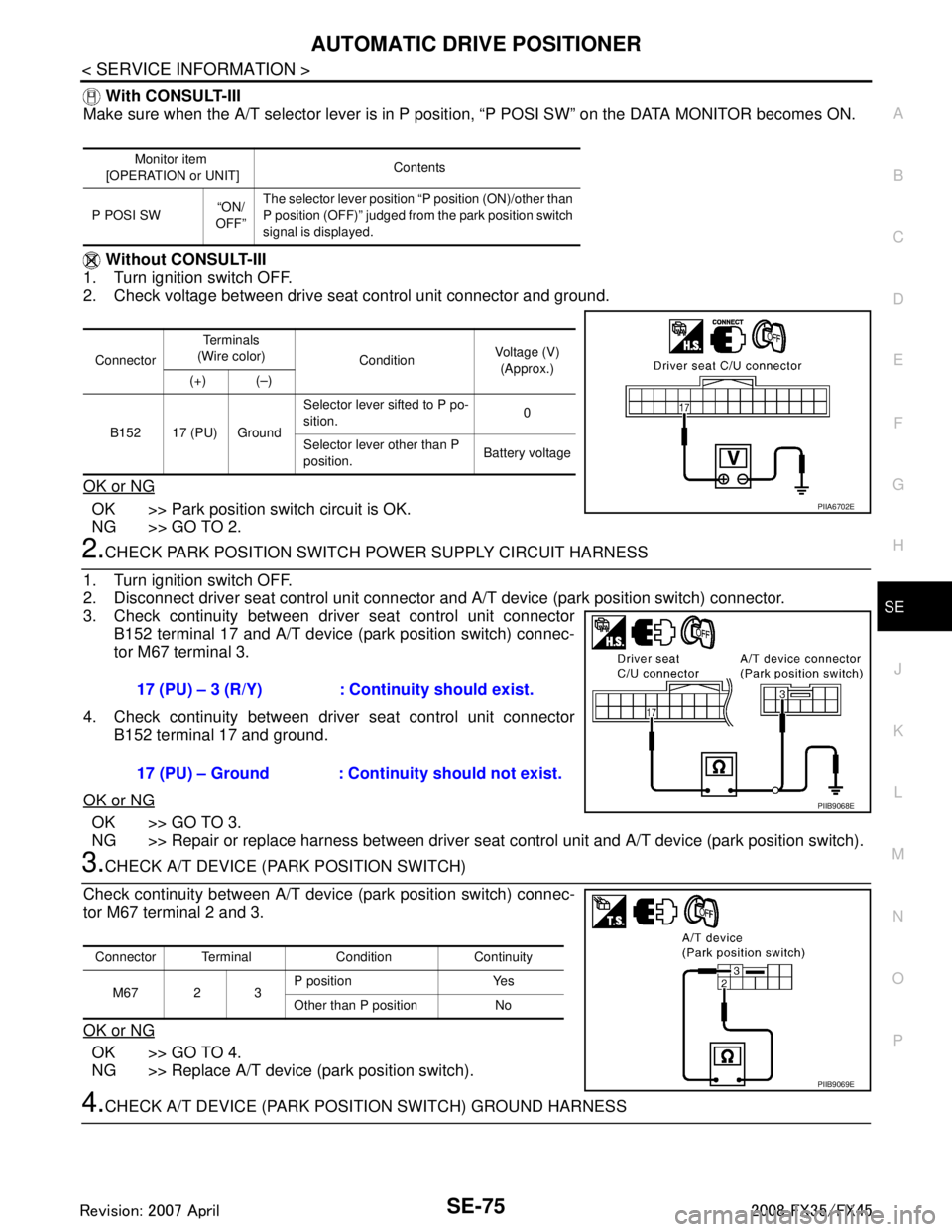
Make sure when the A/T selector lever is in P posit ion, “P POSI SW” on the DATA MONITOR becomes ON.
Without CONSULT-III
1. Turn ignition switch OFF.
2. Check voltage between drive seat control unit connector and ground.
OK or NG
OK >> Park position switch circuit is OK.
NG >> GO TO 2.
2.CHECK PARK POSITION SWIT CH POWER SUPPLY CIRCUIT HARNESS
1. Turn ignition switch OFF.
2. Disconnect driver seat control unit connector and A/T device (park position switch) connector.
3. Check continuity between driver seat control unit connector
B152 terminal 17 and A/T device (park position switch) connec-
tor M67 terminal 3.
4. Check continuity between driver seat control unit connector B152 terminal 17 and ground.
OK or NG
OK >> GO TO 3.
NG >> Repair or replace harness between driver seat control unit and A/T device (park position switch).
3.CHECK A/T DEVICE (PARK POSITION SWITCH)
Check continuity between A/T devic e (park position switch) connec-
tor M67 terminal 2 and 3.
OK or NG
OK >> GO TO 4.
NG >> Replace A/T device (park position switch).
4.CHECK A/T DEVICE (PARK POSI TION SWITCH) GROUND HARNESS
Monitor item
[OPERATION or UNIT] Contents
P POSI SW “ON/
OFF” The selector lever position “P position (ON)/other than
P position (OFF)” judged from the park position switch
signal is displayed.
Connector Te r m i n a l s
(Wire color) ConditionVoltage (V)
(Approx.)
(+) (–)
B152 17 (PU) Ground Selector lever sifted to P po-
sition.
0
Selector lever other than P
position. Battery voltage
PIIA6702E
17 (PU) – 3 (R/Y) : Continuity should exist.
17 (PU) – Ground : Continuity should not exist.
PIIB9068E
Connector Terminal Condition Continuity
M67 2 3 P position Yes
Other than P position No
PIIB9069E
3AA93ABC3ACD3AC03ACA3AC03AC63AC53A913A773A893A873A873A8E3A773A983AC73AC93AC03AC3
3A893A873A873A8F3A773A9D3AAF3A8A3A8C3A863A9D3AAF3A8B3A8C
Page 3715 of 3924
SE-76
< SERVICE INFORMATION >
AUTOMATIC DRIVE POSITIONER
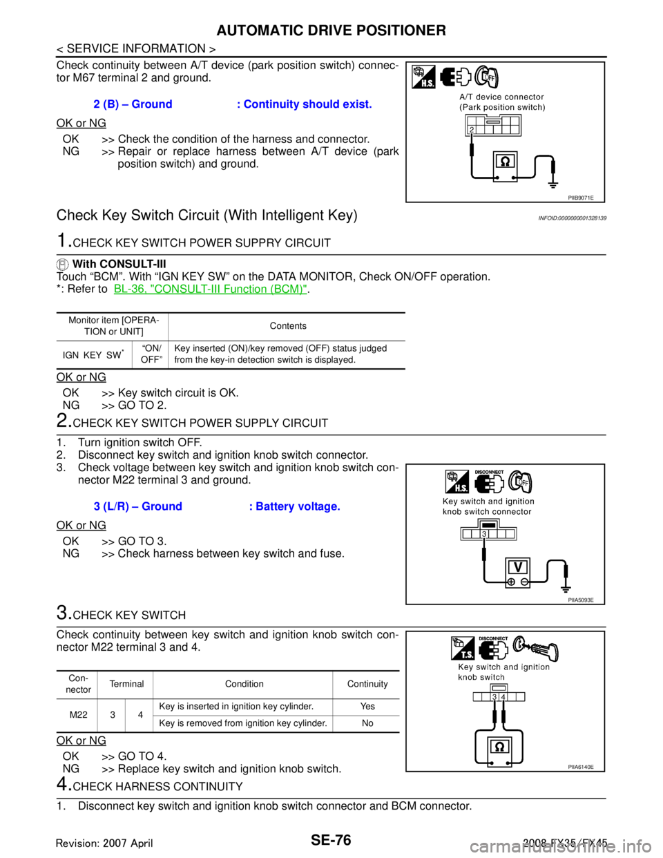
Check continuity between A/T device (park position switch) connec-
tor M67 terminal 2 and ground.
OK or NG
OK >> Check the condition of the harness and connector.
NG >> Repair or replace harness between A/T device (park position switch) and ground.
Check Key Switch Circuit (With Intelligent Key)INFOID:0000000001328139
1.CHECK KEY SWITCH POWER SUPPRY CIRCUIT
With CONSULT-III
Touch “BCM”. With “IGN KEY SW” on the DATA MONITOR, Check ON/OFF operation.
*: Refer to BL-36, "
CONSULT-III Function (BCM)".
OK or NG
OK >> Key switch circuit is OK.
NG >> GO TO 2.
2.CHECK KEY SWITCH PO WER SUPPLY CIRCUIT
1. Turn ignition switch OFF.
2. Disconnect key switch and ignition knob switch connector.
3. Check voltage between key switch and ignition knob switch con- nector M22 terminal 3 and ground.
OK or NG
OK >> GO TO 3.
NG >> Check harness between key switch and fuse.
3.CHECK KEY SWITCH
Check continuity between key switch and ignition knob switch con-
nector M22 terminal 3 and 4.
OK or NG
OK >> GO TO 4.
NG >> Replace key switch and ignition knob switch.
4.CHECK HARNESS CONTINUITY
1. Disconnect key switch and ignition knob switch connector and BCM connector. 2 (B) – Ground : Continuity should exist.
PIIB9071E
Monitor item [OPERA-
TION or UNIT] Contents
IGN KEY SW
*“ON/
OFF” Key inserted (ON)/key removed (OFF) status judged
from the key-in detection switch is displayed.
3 (L/R) – Ground : Battery voltage.
PIIA5093E
Con-
nector Terminal Condition Continuity
M22 3 4 Key is inserted in ignition key cylinder. Yes
Key is removed from ignition key cylinder. No
PIIA6140E
3AA93ABC3ACD3AC03ACA3AC03AC63AC53A913A773A893A873A873A8E3A773A983AC73AC93AC03AC3
3A893A873A873A8F3A773A9D3AAF3A8A3A8C3A863A9D3AAF3A8B3A8C
Page 3716 of 3924
AUTOMATIC DRIVE POSITIONERSE-77
< SERVICE INFORMATION >
C
DE
F
G H
J
K L
M A
B
SE
N
O P
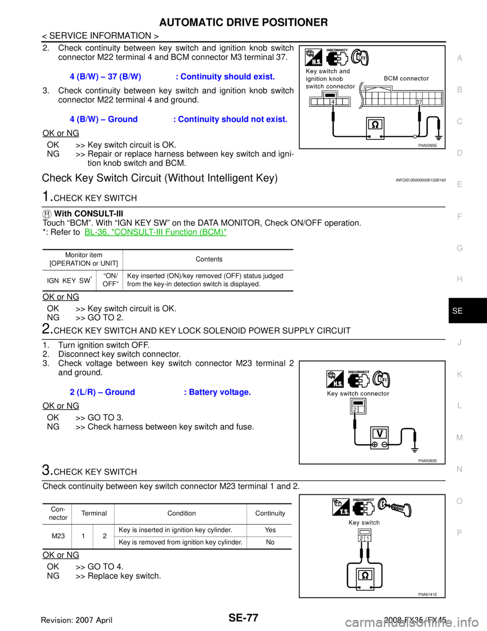
2. Check continuity between key switch and ignition knob switch connector M22 terminal 4 and BCM connector M3 terminal 37.
3. Check continuity between key switch and ignition knob switch connector M22 terminal 4 and ground.
OK or NG
OK >> Key switch circuit is OK.
NG >> Repair or replace harness between key switch and igni- tion knob switch and BCM.
Check Key Switch Circui t (Without Intelligent Key)INFOID:0000000001328140
1.CHECK KEY SWITCH
With CONSULT-III
Touch “BCM”. With “IGN KEY SW” on the DATA MONITOR, Check ON/OFF operation.
*: Refer to BL-36, "
CONSULT-III Function (BCM)"
OK or NG
OK >> Key switch circuit is OK.
NG >> GO TO 2.
2.CHECK KEY SWITCH AND KEY LOCK SOLENOID POWER SUPPLY CIRCUIT
1. Turn ignition switch OFF.
2. Disconnect key switch connector.
3. Check voltage between key switch connector M23 terminal 2 and ground.
OK or NG
OK >> GO TO 3.
NG >> Check harness between key switch and fuse.
3.CHECK KEY SWITCH
Check continuity between key switch connector M23 terminal 1 and 2.
OK or NG
OK >> GO TO 4.
NG >> Replace key switch. 4 (B/W) – 37 (B/W) : Cont
inuity should exist.
4 (B/W) – Ground : Continuity should not exist.
PIIA5095E
Monitor item
[OPERATION or UNIT] Contents
IGN KEY SW
*“ON/
OFF” Key inserted (ON)/key removed (OFF) status judged
from the key-in detection switch is displayed.
2 (L/R) – Ground : Battery voltage.
PIIA5092E
Con-
nector Terminal Condition Continuity
M23 1 2 Key is inserted in ignition key cylinder. Yes
Key is removed from ignition key cylinder. No
PIIA6141E
3AA93ABC3ACD3AC03ACA3AC03AC63AC53A913A773A893A873A873A8E3A773A983AC73AC93AC03AC3
3A893A873A873A8F3A773A9D3AAF3A8A3A8C3A863A9D3AAF3A8B3A8C
Page 3717 of 3924
SE-78
< SERVICE INFORMATION >
AUTOMATIC DRIVE POSITIONER
4.CHECK HARNESS CONTINUITY
1. Disconnect key switch connector and BCM connector.
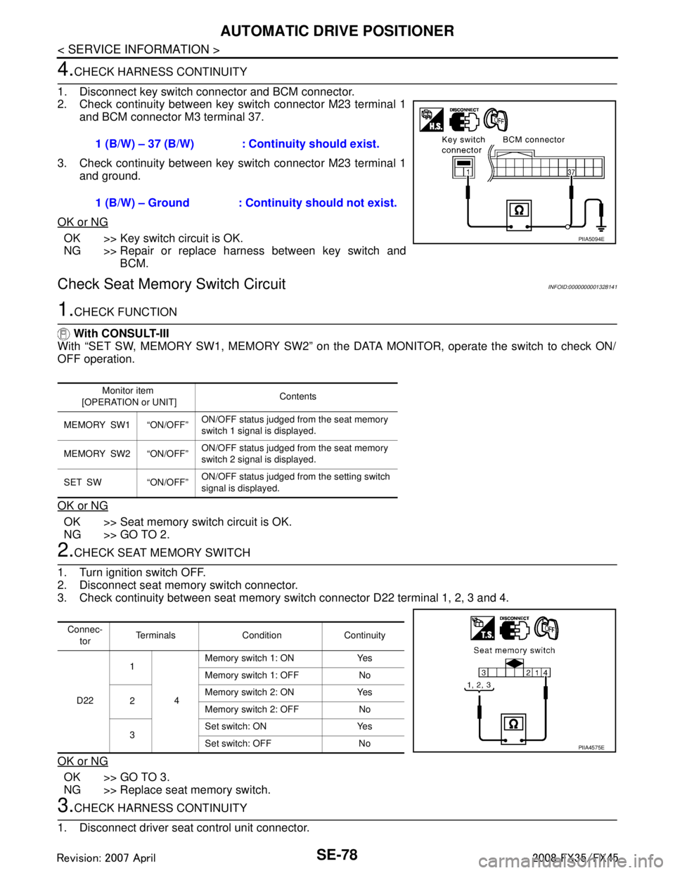
2. Check continuity between key switch connector M23 terminal 1 and BCM connector M3 terminal 37.
3. Check continuity between key switch connector M23 terminal 1 and ground.
OK or NG
OK >> Key switch circuit is OK.
NG >> Repair or replace harness between key switch and BCM.
Check Seat Memory Switch CircuitINFOID:0000000001328141
1.CHECK FUNCTION
With CONSULT-III
With “SET SW, MEMORY SW1, MEMO RY SW2” on the DATA MONITOR, operate the switch to check ON/
OFF operation.
OK or NG
OK >> Seat memory switch circuit is OK.
NG >> GO TO 2.
2.CHECK SEAT MEMORY SWITCH
1. Turn ignition switch OFF.
2. Disconnect seat memory switch connector.
3. Check continuity between seat memory s witch connector D22 terminal 1, 2, 3 and 4.
OK or NG
OK >> GO TO 3.
NG >> Replace seat memory switch.
3.CHECK HARNESS CONTINUITY
1. Disconnect driver seat control unit connector. 1 (B/W) – 37 (B/W) : Cont
inuity should exist.
1 (B/W) – Ground : Conti nuity should not exist.
PIIA5094E
Monitor item
[OPERATION or UNIT] Contents
MEMORY SW1 “ON/OFF” ON/OFF status judged from the seat memory
switch 1 signal is displayed.
MEMORY SW2 “ON/OFF” ON/OFF status judged from the seat memory
switch 2 signal is displayed.
SET SW “ON/OFF” ON/OFF status judged from the setting switch
signal is displayed.
Connec-
tor Terminals Condition Continuity
D22 1
4Memory switch 1: ON Yes
Memory switch 1: OFF No
2 Memory switch 2: ON Yes
Memory switch 2: OFF No
3 Set switch: ON Yes
Set switch: OFF No
PIIA4575E
3AA93ABC3ACD3AC03ACA3AC03AC63AC53A913A773A893A873A873A8E3A773A983AC73AC93AC03AC3
3A893A873A873A8F3A773A9D3AAF3A8A3A8C3A863A9D3AAF3A8B3A8C
Page 3718 of 3924
AUTOMATIC DRIVE POSITIONERSE-79
< SERVICE INFORMATION >
C
DE
F
G H
J
K L
M A
B
SE
N
O P
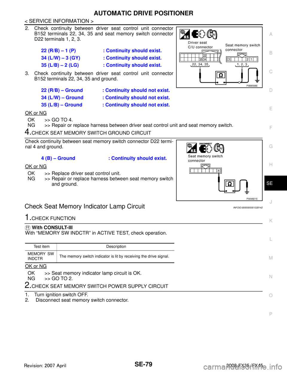
2. Check continuity between driver seat control unit connector B152 terminals 22, 34, 35 and seat memory switch connector
D22 terminals 1, 2, 3.
3. Check continuity between driver seat control unit connector B152 terminals 22, 34, 35 and ground.
OK or NG
OK >> GO TO 4.
NG >> Repair or replace harness between driver seat control unit and seat memory switch.
4.CHECK SEAT MEMORY SWITCH GROUND CIRCUIT
Check continuity between seat memory switch connector D22 termi-
nal 4 and ground.
OK or NG
OK >> Replace driver seat control unit.
NG >> Repair or replace harness between seat memory switch and ground.
Check Seat Memory I ndicator Lamp CircuitINFOID:0000000001328142
1.CHECK FUNCTION
With CONSULT-III
With “MEMORY SW INDCTR” in ACTIVE TEST, check operation.
OK or NG
OK >> Seat memory indicator lamp circuit is OK.
NG >> GO TO 2.
2.CHECK SEAT MEMORY SWITCH POWER SUPPLY CIRCUIT
1. Turn ignition switch OFF.
2. Disconnect seat memory switch connector. 22 (R/B) – 1 (P) : Continuity should exist.
34 (L/W) – 3 (GY) : Cont
inuity should exist.
35 (L/B) – 2 (LG) : Cont inuity should exist.
22 (R/B) – Ground : Continuity should not exist.
34 (L/W) – Ground : Continuity should not exist.
35 (L/B) – Ground : Continuity should not exist.
PIIB8598E
4 (B) – Ground : Continuity should exist.
PIIA4821E
Test item Description
MEMORY SW
INDCTR The memory switch indicator is lit by receiving the drive signal.
3AA93ABC3ACD3AC03ACA3AC03AC63AC53A913A773A893A873A873A8E3A773A983AC73AC93AC03AC3
3A893A873A873A8F3A773A9D3AAF3A8A3A8C3A863A9D3AAF3A8B3A8C
Page 3719 of 3924
SE-80
< SERVICE INFORMATION >
AUTOMATIC DRIVE POSITIONER
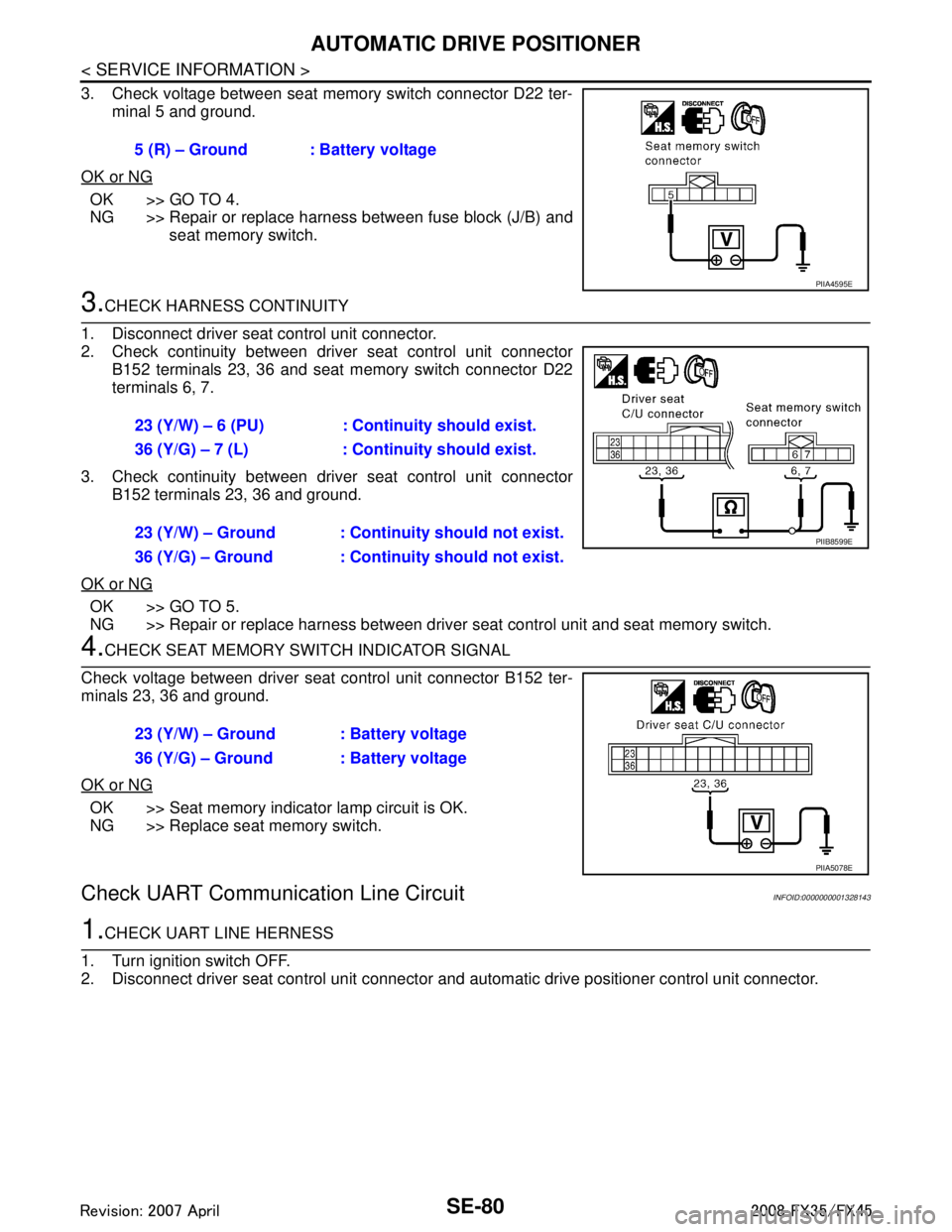
3. Check voltage between seat memory switch connector D22 ter-minal 5 and ground.
OK or NG
OK >> GO TO 4.
NG >> Repair or replace harness between fuse block (J/B) and seat memory switch.
3.CHECK HARNESS CONTINUITY
1. Disconnect driver seat control unit connector.
2. Check continuity between driv er seat control unit connector
B152 terminals 23, 36 and seat memory switch connector D22
terminals 6, 7.
3. Check continuity between driv er seat control unit connector
B152 terminals 23, 36 and ground.
OK or NG
OK >> GO TO 5.
NG >> Repair or replace harness between driver seat control unit and seat memory switch.
4.CHECK SEAT MEMORY SWITCH INDICATOR SIGNAL
Check voltage between driver seat control unit connector B152 ter-
minals 23, 36 and ground.
OK or NG
OK >> Seat memory indicator lamp circuit is OK.
NG >> Replace seat memory switch.
Check UART Communication Line CircuitINFOID:0000000001328143
1.CHECK UART LINE HERNESS
1. Turn ignition switch OFF.
2. Disconnect driver seat control unit connector and automatic drive positioner control unit connector.
5 (R) – Ground : Battery voltage
PIIA4595E
23 (Y/W) – 6 (PU) : Continuity should exist.
36 (Y/G) – 7 (L) : Continuity should exist.
23 (Y/W) – Ground : Continuity should not exist.
36 (Y/G) – Ground : Continuity should not exist.
PIIB8599E
23 (Y/W) – Ground : Battery voltage
36 (Y/G) – Ground : Battery voltage
PIIA5078E
3AA93ABC3ACD3AC03ACA3AC03AC63AC53A913A773A893A873A873A8E3A773A983AC73AC93AC03AC3
3A893A873A873A8F3A773A9D3AAF3A8A3A8C3A863A9D3AAF3A8B3A8C
Page 3720 of 3924
AUTOMATIC DRIVE POSITIONERSE-81
< SERVICE INFORMATION >
C
DE
F
G H
J
K L
M A
B
SE
N
O P
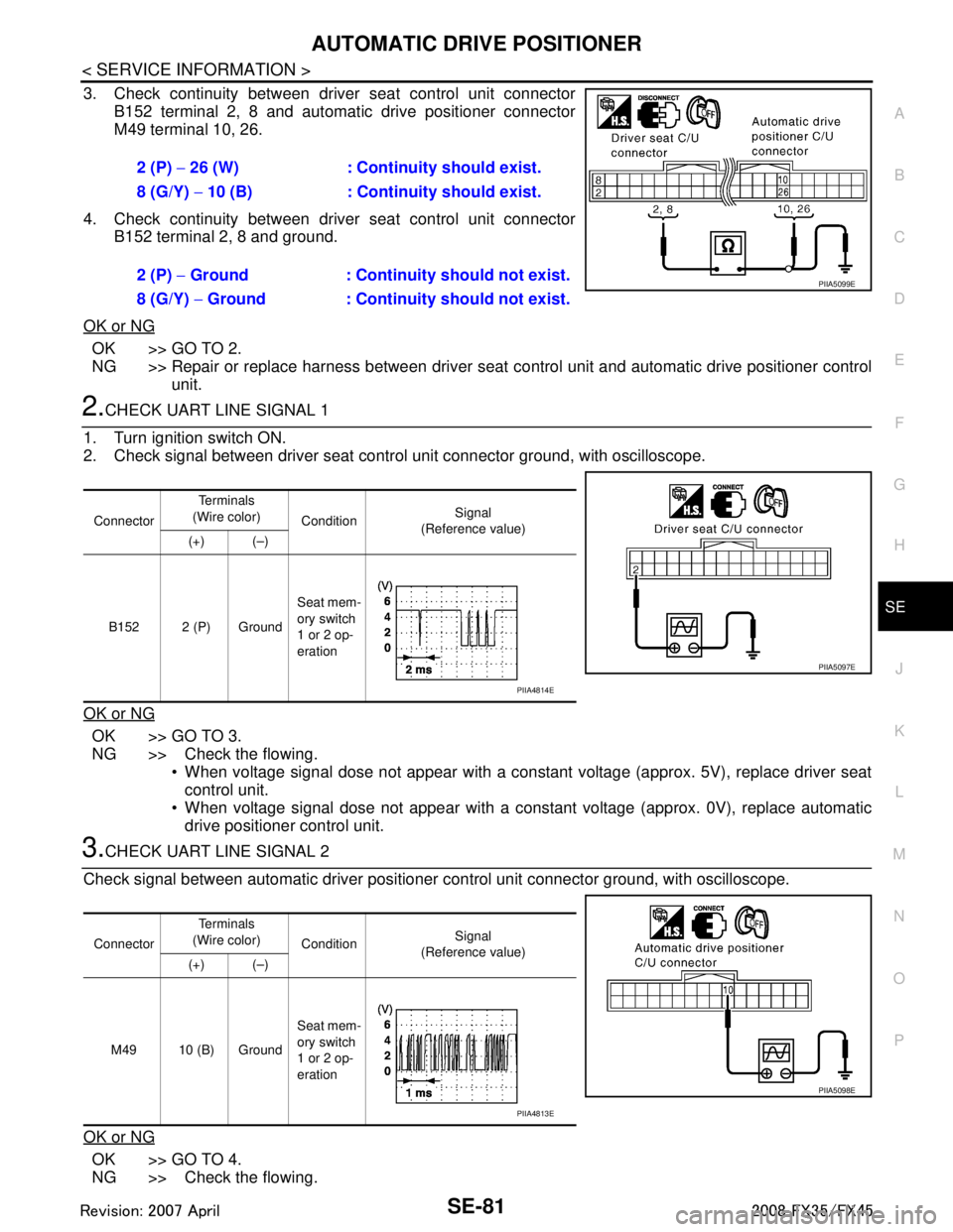
3. Check continuity between driver seat control unit connector B152 terminal 2, 8 and automatic drive positioner connector
M49 terminal 10, 26.
4. Check continuity between driver seat control unit connector B152 terminal 2, 8 and ground.
OK or NG
OK >> GO TO 2.
NG >> Repair or replace harness between driver seat control unit and automatic drive positioner control
unit.
2.CHECK UART LINE SIGNAL 1
1. Turn ignition switch ON.
2. Check signal between driver seat contro l unit connector ground, with oscilloscope.
OK or NG
OK >> GO TO 3.
NG >> Check the flowing. When voltage signal dose not appear with a constant voltage (approx. 5V), replace driver seat
control unit.
When voltage signal dose not appear with a const ant voltage (approx. 0V), replace automatic
drive positioner control unit.
3.CHECK UART LINE SIGNAL 2
Check signal between automatic driver positioner control unit connector ground, with oscilloscope.
OK or NG
OK >> GO TO 4.
NG >> Check the flowing. 2 (P)
− 26 (W) : Continuity should exist.
8 (G/Y) − 10 (B) : Continui ty should exist.
2 (P) − Ground : Continuity should not exist.
8 (G/Y) − Ground : Continuity should not exist.
PIIA5099E
Connector Te r m i n a l s
(Wire color) Condition Signal
(Reference value)
(+) (–)
B152 2 (P) Ground Seat mem-
ory switch
1 or 2 op-
eration
PIIA5097E
PIIA4814E
Connector
Te r m i n a l s
(Wire color) Condition Signal
(Reference value)
(+) (–)
M49 10 (B) Ground Seat mem-
ory switch
1 or 2 op-
eration
PIIA5098E
PIIA4813E
3AA93ABC3ACD3AC03ACA3AC03AC63AC53A913A773A893A873A873A8E3A773A983AC73AC93AC03AC3
3A893A873A873A8F3A773A9D3AAF3A8A3A8C3A863A9D3AAF3A8B3A8C
Page 3721 of 3924
SE-82
< SERVICE INFORMATION >
AUTOMATIC DRIVE POSITIONER
When voltage signal dose not appear with a constant voltage (approx. 5V), replace automatic
driver seat control unit.
When voltage signal dose not appear with a constant voltage (approx. 0V), replace driver seat
control unit.
4.CHECK DRIVER SEAT CONTROL UNIT
Dose the automatic drive positioner operate, when the driver seat control unit exchanged?
Does seat memory function operate?
YES >> Replace automatic drive positioner control unit.
NG >> Replace driver seat control unit.
Check Lumbar Support CircuitINFOID:0000000001328144
1.CHECK LUMBAR SUPPORT SWITCH
1. Turn ignition switch OFF.
2. Disconnect lumbar support switch connector.
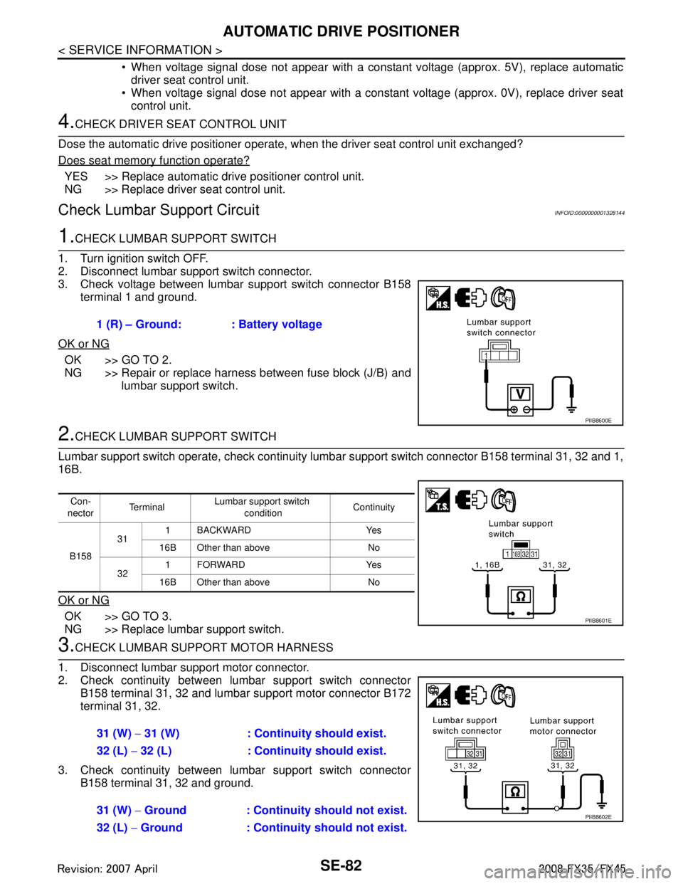
3. Check voltage between lumbar support switch connector B158 terminal 1 and ground.
OK or NG
OK >> GO TO 2.
NG >> Repair or replace harness between fuse block (J/B) and lumbar support switch.
2.CHECK LUMBAR SUPPORT SWITCH
Lumbar support switch operate, check continuity lum bar support switch connector B158 terminal 31, 32 and 1,
16B.
OK or NG
OK >> GO TO 3.
NG >> Replace lumbar support switch.
3.CHECK LUMBAR SUPPORT MOTOR HARNESS
1. Disconnect lumbar support motor connector.
2. Check continuity between lumbar support switch connector B158 terminal 31, 32 and lumbar support motor connector B172
terminal 31, 32.
3. Check continuity between lumbar support switch connector B158 terminal 31, 32 and ground.1 (R) – Ground: : Battery voltage
PIIB8600E
Con-
nector Te r m i n a l
Lumbar support switch
condition Continuity
B158 31
1 BACKWARD Yes
16B Other than above No
32 1FORWARD Yes
16B Other than above No
PIIB8601E
31 (W) − 31 (W) : Continuity should exist.
32 (L) − 32 (L) : Continuity should exist.
31 (W) − Ground : Continuity should not exist.
32 (L) − Ground : Continuity should not exist.
PIIB8602E
3AA93ABC3ACD3AC03ACA3AC03AC63AC53A913A773A893A873A873A8E3A773A983AC73AC93AC03AC3
3A893A873A873A8F3A773A9D3AAF3A8A3A8C3A863A9D3AAF3A8B3A8C