2008 INFINITI FX35 sensor
[x] Cancel search: sensorPage 2912 of 3924

GI-50
< SERVICE INFORMATION >
TERMINOLOGY
Nonvolatile random access memory NVRAM ***
On board diagnostic system OBD system Self-diagnosis
Open loop OL Open loop
Oxidation catalyst OC Catalyst
Oxidation catalytic converter system OC system ***
Oxygen sensor O2S Exhaust gas sensor
Park position switch *** Park switch
Park/neutral position switch PNP switchPark/neutral switch
Inhibitor switch
Neutral position switch
Periodic trap oxidizer system PTOX system ***
Positive crankcase ventilation PCV Positive crankcase ventilation
Positive crankcase ventilation valve PCV valve PCV valve
Powertrain cont rol module PCM ***
Programmable read only memory PROM ***
Pulsed secondary air injection control sole-
noid valve PAIRC solenoid valve AIV control solenoid valve
Pulsed secondary air injection system PAIR system Air induction valve (AIV) control
Pulsed secondary air injection valve PAIR valve Air induction valve
Random access memory RAM ***
Read only memory ROM ***
Scan tool ST ***
Secondary air injection pump AIR pump ***
Secondary air injection system AIR system ***
Sequential multiport fuel injection system SFI system Sequential fuel injection
Service reminder indicator SRI ***
Simultaneous multiport fuel injection sys-
tem *** Simultaneous fuel injection
Smoke puff limiter system SPL system ***
Supercharger SC ***
Supercharger bypass SCB ***
System readiness test SRT ***
Thermal vacuum valve TVV Thermal vacuum valve
Three way catalyst TWC Catalyst
Three way catalytic converter system TWC system ***
Three way + oxidation catalyst TWC + OC Catalyst
Three way + oxidation catalytic converter
system TWC + OC system ***
Throttle body TB Throttle chamber
SPI body
Throttle body fuel injection system TBI system Fuel injection control
Throttle position TP Throttle position
Throttle position sensor TPS Throttle sensor
Throttle position switch TP switch Throttle switch
Torque converter clutch solenoid valve TCC solenoid valve Lock-up cancel solenoid
Lock-up solenoid
NEW TERM
NEW ACRONYM /
ABBREVIATION OLD TERM
3AA93ABC3ACD3AC03ACA3AC03AC63AC53A913A773A893A873A873A8E3A773A983AC73AC93AC03AC3
3A893A873A873A8F3A773A9D3AAF3A8A3A8C3A863A9D3AAF3A8B3A8C
Page 2913 of 3924

TERMINOLOGYGI-51
< SERVICE INFORMATION >
C
DE
F
G H
I
J
K L
M B
GI
N
O P
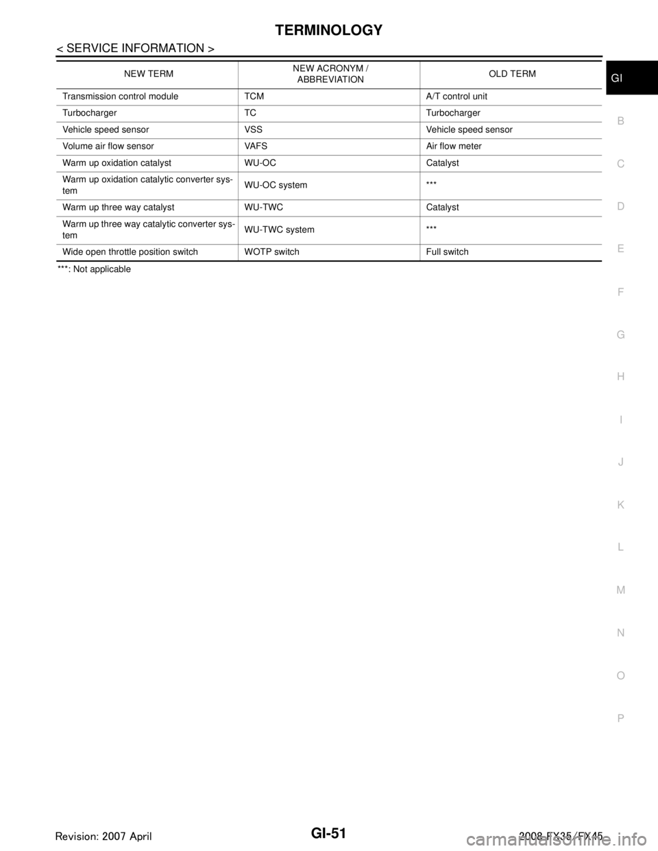
***: Not applicable Transmission control module TCM A/T control unit
Turbocharger TC Turbocharger
Vehicle speed sensor VSS Vehicle speed sensor
Volume air flow sensor VAFS Air flow meter
Warm up oxidation catalyst WU-OC Catalyst
Warm up oxidation catalytic converter sys-
tem
WU-OC system ***
Warm up three way catalyst WU-TWC Catalyst
Warm up three way catalytic converter sys-
tem WU-TWC system ***
Wide open throttle position switch WOTP switch Full switch NEW TERM
NEW ACRONYM /
ABBREVIATION OLD TERM
3AA93ABC3ACD3AC03ACA3AC03AC63AC53A913A773A893A873A873A8E3A773A983AC73AC93AC03AC3
3A893A873A873A8F3A773A9D3AAF3A8A3A8C3A863A9D3AAF3A8B3A8C
Page 3015 of 3924

IP-14
< SERVICE INFORMATION >
INSTRUMENT PANEL ASSEMBLY
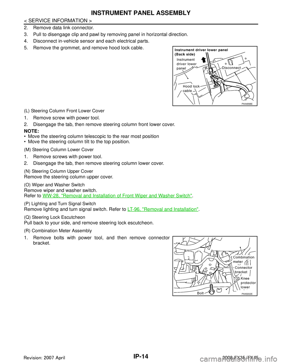
2. Remove data link connector.
3. Pull to disengage clip and pawl by removing panel in horizontal direction.
4. Disconnect in-vehicle sensor and each electrical parts.
5. Remove the grommet, and remove hood lock cable.
(L) Steering Column Front Lower Cover
1. Remove screw with power tool.
2. Disengage the tab, then remove steering column front lower cover.
NOTE:
Move the steering column telescopic to the rear most position
Move the steering column tilt to the top position.
(M) Steering Column Lower Cover
1. Remove screws with power tool.
2. Disengage the tab, then remove steering column lower cover.
(N) Steering Column Upper Cover
Remove the steering column upper cover.
(O) Wiper and Washer Switch
Remove wiper and washer switch.
Refer to WW-28, "
Removal and Installation of Front Wiper and Washer Switch".
(P) Lighting and Turn Signal Switch
Remove lighting and turn signal switch. Refer to LT-96, "Removal and Installation".
(Q) Steering Lock Escutcheon
Pull back to your side, and remove steering lock escutcheon.
(R) Combination Meter Assembly
1. Remove bolts with power tool, and then remove connector
bracket.
PIIA4998E
PIIA5002E
3AA93ABC3ACD3AC03ACA3AC03AC63AC53A913A773A893A873A873A8E3A773A983AC73AC93AC03AC3
3A893A873A873A8F3A773A9D3AAF3A8A3A8C3A863A9D3AAF3A8B3A8C
Page 3021 of 3924

LAN-1
ELECTRICAL
C
DE
F
G H
I
J
L
M
SECTION LAN
A
B
LAN
N
O P
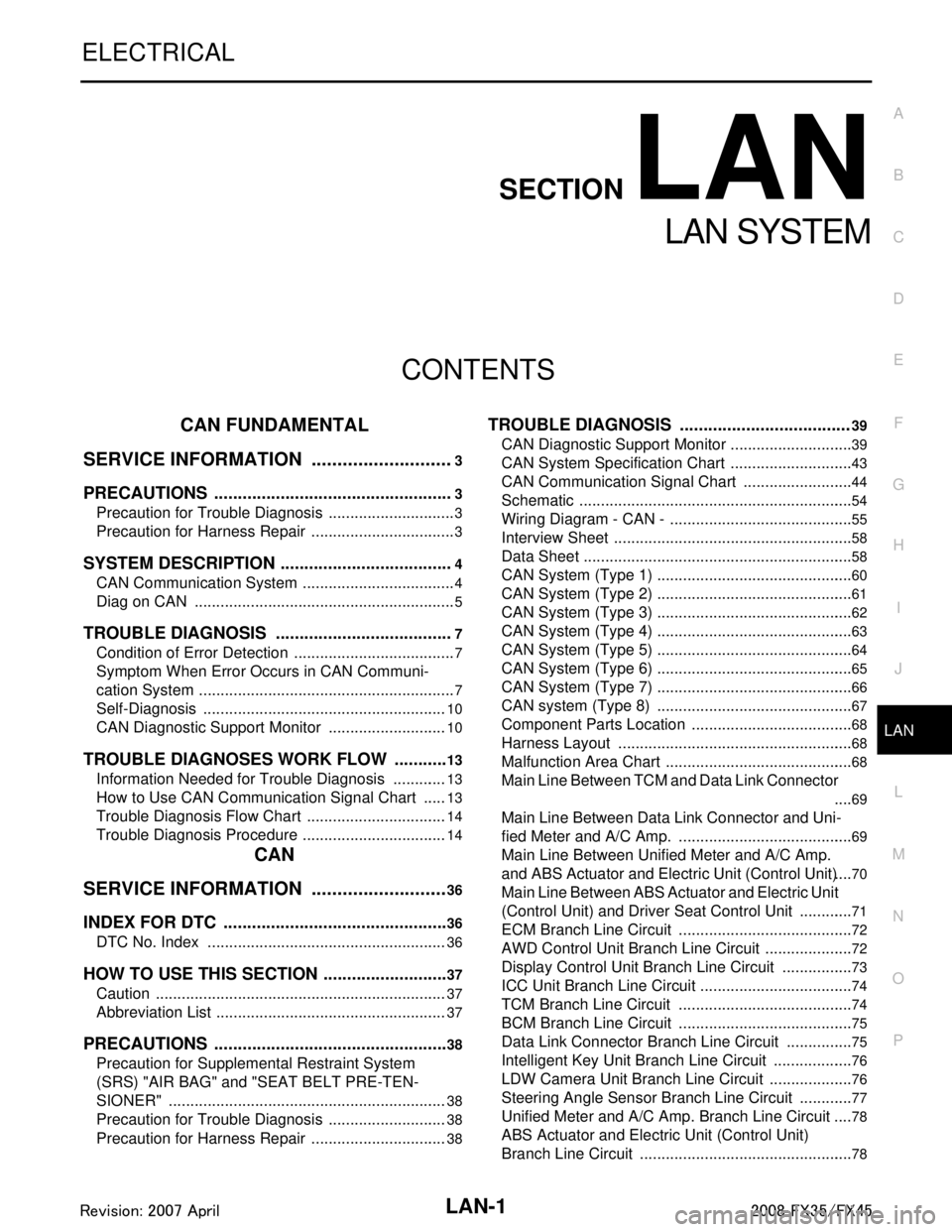
CONTENTS
LAN SYSTEM
CAN FUNDAMENTAL
SERVICE INFORMATION .. ..........................
3
PRECAUTIONS .............................................. .....3
Precaution for Trouble Diagnosis ........................ ......3
Precaution for Harness Repair ..................................3
SYSTEM DESCRIPTION .....................................4
CAN Communication System .............................. ......4
Diag on CAN .............................................................5
TROUBLE DIAGNOSIS ......................................7
Condition of Error Detection ................................ ......7
Symptom When Error Occurs in CAN Communi-
cation System ...................................................... ......
7
Self-Diagnosis .........................................................10
CAN Diagnostic Support Monitor ............................10
TROUBLE DIAGNOSES WORK FLOW ............13
Information Needed for Trouble Diagnosis ......... ....13
How to Use CAN Communication Signal Chart ......13
Trouble Diagnosis Flow Chart .................................14
Trouble Diagnosis Procedure ..................................14
CAN
SERVICE INFORMATION .. .........................
36
INDEX FOR DTC ............................................ ....36
DTC No. Index .................................................... ....36
HOW TO USE THIS SECTION ...........................37
Caution ................................................................ ....37
Abbreviation List ......................................................37
PRECAUTIONS ..................................................38
Precaution for Supplemental Restraint System
(SRS) "AIR BAG" and "SEAT BELT PRE-TEN-
SIONER" ............................................................. ....
38
Precaution for Trouble Diagnosis ............................38
Precaution for Harness Repair ................................38
TROUBLE DIAGNOSIS ....................................39
CAN Diagnostic Support Monitor ......................... ....39
CAN System Specification Chart .............................43
CAN Communication Signal Chart ..........................44
Schematic ................................................................54
Wiring Diagram - CAN - ...........................................55
Interview Sheet ........................................................58
Data Sheet ...............................................................58
CAN System (Type 1) ..............................................60
CAN System (Type 2) ..............................................61
CAN System (Type 3) ..............................................62
CAN System (Type 4) ..............................................63
CAN System (Type 5) ..............................................64
CAN System (Type 6) ..............................................65
CAN System (Type 7) ..............................................66
CAN system (Type 8) ..............................................67
Component Parts Location ......................................68
Harness Layout .......................................................68
Malfunction Area Chart ............................................68
Main Line Between TCM and Data Link Connector
....
69
Main Line Between Data Link Connector and Uni-
fied Meter and A/C Amp. .........................................
69
Main Line Between Unified Meter and A/C Amp.
and ABS Actuator and Electric Unit (Control Unit) ....
70
Main Line Between ABS Actu ator and Electric Unit
(Control Unit) and Driver Seat Control Unit .............
71
ECM Branch Line Circuit ..................................... ....72
AWD Control Unit Branch Line Circuit .....................72
Display Control Unit Branch Line Circuit .................73
ICC Unit Branch Line Circuit ................................ ....74
TCM Branch Line Circuit .........................................74
BCM Branch Line Circuit .........................................75
Data Link Connector Branch Line Circuit ................75
Intelligent Key Unit Branch Line Circuit ...................76
LDW Camera Unit Branch Line Circuit ....................76
Steering Angle Sensor Branch Line Circuit .............77
Unified Meter and A/C Amp. Branch Line Circuit ....78
ABS Actuator and Electric Unit (Control Unit)
Branch Line Circuit ..................................................
78
3AA93ABC3ACD3AC03ACA3AC03AC63AC53A913A773A893A873A873A8E3A773A983AC73AC93AC03AC3
3A893A873A873A8F3A773A9D3AAF3A8A3A8C3A863A9D3AAF3A8B3A8C
Page 3022 of 3924

LAN-2
ICC Sensor Branch Line Circuit ..............................79
Driver Seat Control Unit Branch Line Circuit ..........79
IPDM E/R Branch Line Circuit .............................. ...80
CAN Communication Circuit ...................................81
3AA93ABC3ACD3AC03ACA3AC03AC63AC53A913A773A893A873A873A8E3A773A983AC73AC93AC03AC3
3A893A873A873A8F3A773A9D3AAF3A8A3A8C3A863A9D3AAF3A8B3A8C
Page 3057 of 3924
![INFINITI FX35 2008 Service Manual
HOW TO USE THIS SECTIONLAN-37
< SERVICE INFORMATION > [CAN]
C
D
E
F
G H
I
J
L
M A
B
LAN
N
O P
HOW TO USE THIS SECTION
CautionINFOID:0000000001328628
This section describes information peculiar to a INFINITI FX35 2008 Service Manual
HOW TO USE THIS SECTIONLAN-37
< SERVICE INFORMATION > [CAN]
C
D
E
F
G H
I
J
L
M A
B
LAN
N
O P
HOW TO USE THIS SECTION
CautionINFOID:0000000001328628
This section describes information peculiar to a](/manual-img/42/57017/w960_57017-3056.png)
HOW TO USE THIS SECTIONLAN-37
< SERVICE INFORMATION > [CAN]
C
D
E
F
G H
I
J
L
M A
B
LAN
N
O P
HOW TO USE THIS SECTION
CautionINFOID:0000000001328628
This section describes information peculiar to a v ehicle, sheets for trouble diagnosis, and inspection proce-
dures.
For trouble diagnosis procedure LAN-14, "
Trouble Diagnosis Procedure".
Abbreviation ListINFOID:0000000001328629
Abbreviations in CAN communication signal chart, and the diagnosis sheet are as per the following list.
Abbreviation Unit name SELECT SYSTEM
(CONSULT-III) CAN DIAG SUPPORT MNTR
(CONSULT-III)
4WD AWD control unit ALL MODE AWD/4WD AWD/4WD
A-BAG Air bag diagnosis sensor unit AIR BAG – ABS ABS actuator and electric un it (control unit) ABS VDC/TCS/ABS
ADP Driver seat control unit AUTO DRIVE POS. –
BCM BCM BCM BCM/SEC
DISP Display control unit – DISPLAY DLC Data link connector – –
ECM ECM ENGINE ECM
ICC ICC unit ICC ICC
ICC/e4WD
I-KEY Intelligent Key unit INTELLIGENT KEY I-KEY
IPDM-E IPDM E/R IPDM E/R IPDM E/R LANE LDW camera unit LDW –
LASER ICC sensor – ICC SENSOR M&A Unified meter and A/C amp. METER/M&A METER/M&A
STRG Steering angle sensor – STRG TCM TCM TRANSMISSION TCM
3AA93ABC3ACD3AC03ACA3AC03AC63AC53A913A773A893A873A873A8E3A773A983AC73AC93AC03AC3
3A893A873A873A8F3A773A9D3AAF3A8A3A8C3A863A9D3AAF3A8B3A8C
Page 3060 of 3924
![INFINITI FX35 2008 Service Manual
LAN-40
< SERVICE INFORMATION >[CAN]
TROUBLE DIAGNOSIS
TCM
NOTE:
Replace the unit when “NG” is i
ndicated on the “INITIAL DIAG”.
BCM
NOTE:
Replace the unit when “NG” is indicated on the � INFINITI FX35 2008 Service Manual
LAN-40
< SERVICE INFORMATION >[CAN]
TROUBLE DIAGNOSIS
TCM
NOTE:
Replace the unit when “NG” is i
ndicated on the “INITIAL DIAG”.
BCM
NOTE:
Replace the unit when “NG” is indicated on the �](/manual-img/42/57017/w960_57017-3059.png)
LAN-40
< SERVICE INFORMATION >[CAN]
TROUBLE DIAGNOSIS
TCM
NOTE:
Replace the unit when “NG” is i
ndicated on the “INITIAL DIAG”.
BCM
NOTE:
Replace the unit when “NG” is indicated on the “INITIAL DIAG”.
Intelligent Key Unit
ITEMCAN DIAG SUP-
PORT MNTR DescriptionNormal Error
PRSNT
ICC INITIAL DIAG Status of CAN controller
OKNG
TRANSMIT DIAG Signal transmission status
UNKWN
ECM Signal receiving status from the ECM
VDC/TCS/ABS
Signal receiving status from th
e ABS actuator and electric unit
(control unit)
TCM Signal receiving status from the TCM
METER/M&A Not used even though indicated
LANE KEEP
ECM(l)
ICC SENSOR Signal receiving status from the ICC sensor OK UNKWN
STRG
Not used even though indicated
METER/M&A(l)
ERROR(l)
LANE DETEC-
TOR
TCM(l)
BCM/SEC Signal receiving status from the BCM OK UNKWN
ITEM
CAN DIAG SUP-
PORT MNTR DescriptionNormal Error
PRSNT
TCM INITIAL DIAG Status of CAN controller
OKNG
TRANSMIT DIAG Signal transmission status
UNKWN
ECM Signal receiving status from the ECM
VDC/TCS/ABS
Signal receiving status from th
e ABS actuator and electric unit
(control unit)
METER/M&A Signal receiving status from the unified meter and A/C amp.
ICC/e4WD Signal receiving status from the ICC unit
AWD/4WD Signal receiving status from the AWD control unit
ITEM CAN DIAG SUP-
PORT MNTR DescriptionNormal Error
PRSNT
BCM INITIAL DIAG Status of CAN controller
OKNG
TRANSMIT DIAG Signal transmission status
UNKWN
ECM Signal receiving status from the ECM
IPDM E/R Signal receiving status from the IPDM E/R
METER/M&A Signal receiving status from the unified meter and A/C amp.
I-KEY Not used even though indicated
3AA93ABC3ACD3AC03ACA3AC03AC63AC53A913A773A893A873A873A8E3A773A983AC73AC93AC03AC3
3A893A873A873A8F3A773A9D3AAF3A8A3A8C3A863A9D3AAF3A8B3A8C
Page 3062 of 3924
![INFINITI FX35 2008 Service Manual
LAN-42
< SERVICE INFORMATION >[CAN]
TROUBLE DIAGNOSIS
CAUTION:
Never replace the unit even when “NG” is indicated on the “INITIAL DIAG” at this stage. Follow the trouble diagnosis proce-
dure INFINITI FX35 2008 Service Manual
LAN-42
< SERVICE INFORMATION >[CAN]
TROUBLE DIAGNOSIS
CAUTION:
Never replace the unit even when “NG” is indicated on the “INITIAL DIAG” at this stage. Follow the trouble diagnosis proce-
dure](/manual-img/42/57017/w960_57017-3061.png)
LAN-42
< SERVICE INFORMATION >[CAN]
TROUBLE DIAGNOSIS
CAUTION:
Never replace the unit even when “NG” is indicated on the “INITIAL DIAG” at this stage. Follow the trouble diagnosis proce-
dures.
Driver Seat Control Unit
NOTE:
Replace the unit when “NG” is i
ndicated on the “INITIAL DIAG”.
IPDM E/R
0: Error at present, 1 – 39: Error in the past (Number m eans the number of times the ignition switch is turned OFF →ON)
*: 39 or higher number is fixed at 39 until the self-diagnosis result is erased.
MONITOR ITEM LIST (ON-BOARD DIAGNOSIS)
Display Control Unit
NOTE:
CAN diagnostic support monitor of the display control unit is indicated on the vehicle display. Refer to AV-77,
"CAN Diagnostic Support Monitor".
ITEMCAN DIAG SUP-
PORT MNTR DescriptionNormal Error
PRSNT
ABS INITIAL DIAG Status of CAN controller
OKNG
Caution
TRANSMIT DIAG Signal transmission status
UNKWN
ECM Signal receiving status from the ECM
TCM Signal receiving status from the TCM
METER/M&A Not used even though indicated
STRG Signal receiving status from the steering angle sensor OK UNKWN
ICC Not used even though indicated
AWD/4WD Signal receiving status from the AWD control unit OK UNKWN
ITEM CAN DIAG SUP-
PORT MNTR DescriptionNormal Error
PRSNT
ADP INITIAL DIAG Status of CAN controller
OKNG
TRANSMIT DIAG Signal transmission status
UNKWN
BCM/SEC Signal receiving status from the BCM
METER/M&A Signal receiving status from the unified meter and A/C amp.
TCM Signal receiving status from the TCM
ITEM
CAN DIAG SUP-
PORT MNTR Description Normal Error
PRSNT PAST PRSNT PAST
IPDM-E TRANSMIT DIAG Signal transmission status
OKOK
or
1 – 39
*UNKWN 0
ECM Signal receiving status from the ECM
BCM/SEC Signal receiving status from the BCM
PKIB6080E
3AA93ABC3ACD3AC03ACA3AC03AC63AC53A913A773A893A873A873A8E3A773A983AC73AC93AC03AC3
3A893A873A873A8F3A773A9D3AAF3A8A3A8C3A863A9D3AAF3A8B3A8C