2008 INFINITI FX35 Body
[x] Cancel search: BodyPage 1011 of 3924
REAR DISC BRAKEBR-27
< SERVICE INFORMATION >
C
DE
G H
I
J
K L
M A
B
BR
N
O P
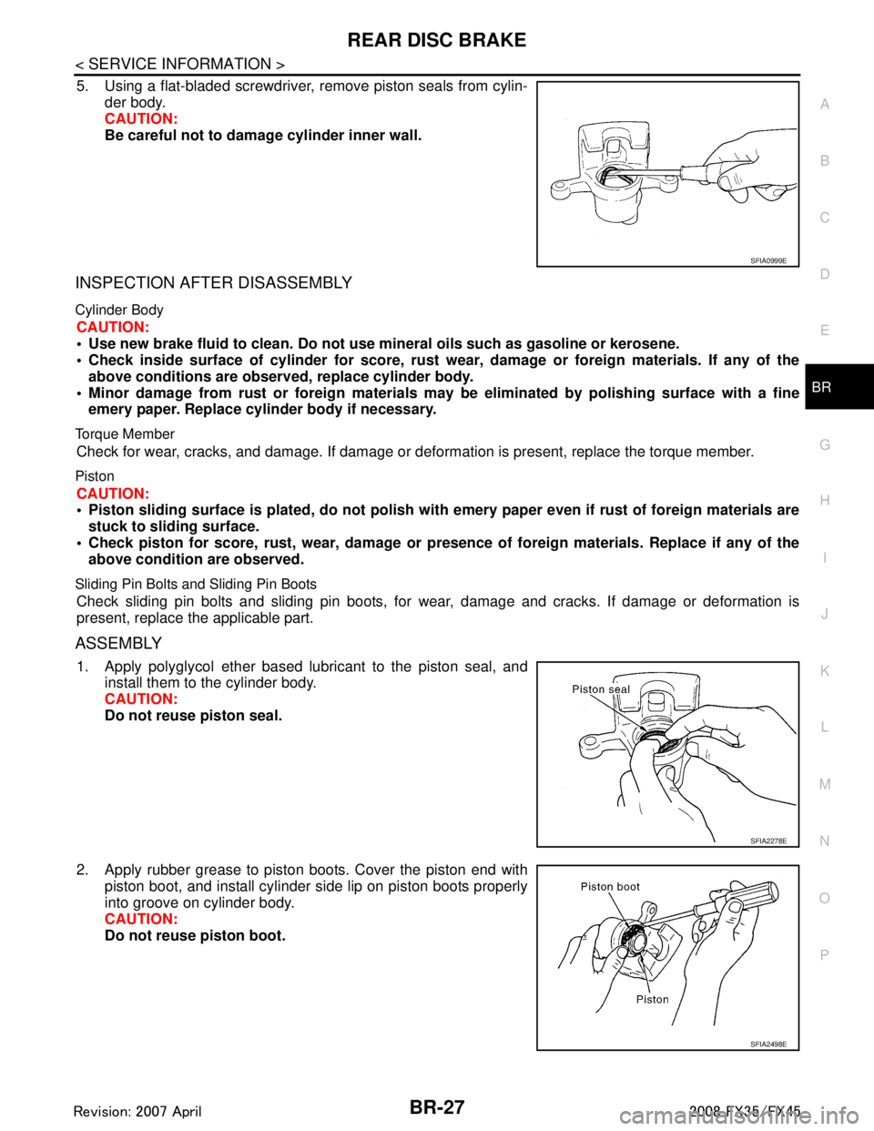
5. Using a flat-bladed screwdriver, remove piston seals from cylin- der body.
CAUTION:
Be careful not to damage cylinder inner wall.
INSPECTION AFTER DISASSEMBLY
Cylinder Body
CAUTION:
Use new brake fluid to clean. Do not use mine ral oils such as gasoline or kerosene.
Check inside surface of cylinder for score, rust wear , damage or foreign materials. If any of the
above conditions are obser ved, replace cylinder body.
Minor damage from rust or foreign materials m ay be eliminated by polishing surface with a fine
emery paper. Replace cylinder body if necessary.
Torque Member
Check for wear, cracks, and damage. If damage or def ormation is present, replace the torque member.
Piston
CAUTION:
Piston sliding surface is plated, do not polish with emery paper even if rust of foreign materials are
stuck to sliding surface.
Check piston for score, rust, wear , damage or presence of foreign materials. Replace if any of the
above condition are observed.
Sliding Pin Bolts and Sliding Pin Boots
Check sliding pin bolts and sliding pin boots, for wear, damage and cracks. If damage or deformation is
present, replace the applicable part.
ASSEMBLY
1. Apply polyglycol ether based lubricant to the piston seal, and install them to the cylinder body.
CAUTION:
Do not reuse piston seal.
2. Apply rubber grease to piston boots. Cover the piston end with piston boot, and install cylinder side lip on piston boots properly
into groove on cylinder body.
CAUTION:
Do not reuse piston boot.
SFIA0999E
SFIA2278E
SFIA2498E
3AA93ABC3ACD3AC03ACA3AC03AC63AC53A913A773A893A873A873A8E3A773A983AC73AC93AC03AC3
3A893A873A873A8F3A773A9D3AAF3A8A3A8C3A863A9D3AAF3A8B3A8C
Page 1012 of 3924
BR-28
< SERVICE INFORMATION >
REAR DISC BRAKE
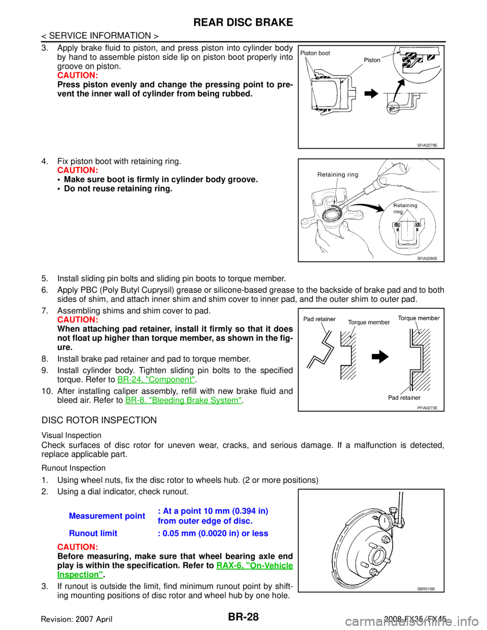
3. Apply brake fluid to piston, and press piston into cylinder bodyby hand to assemble piston side lip on piston boot properly into
groove on piston.
CAUTION:
Press piston evenly and change the pressing point to pre-
vent the inner wall of cylinder from being rubbed.
4. Fix piston boot with retaining ring. CAUTION:
Make sure boot is firmly in cylinder body groove.
Do not reuse retaining ring.
5. Install sliding pin bolts and sliding pin boots to torque member.
6. Apply PBC (Poly Butyl Cuprysil) grease or silicone- based grease to the backside of brake pad and to both
sides of shim, and attach inner shim and shim cover to inner pad, and the outer shim to outer pad.
7. Assembling shims and shim cover to pad. CAUTION:
When attaching pad retainer, inst all it firmly so that it does
not float up higher than torque member, as shown in the fig-
ure.
8. Install brake pad retainer and pad to torque member.
9. Install cylinder body. Tighten sliding pin bolts to the specified torque. Refer to BR-24, "
Component".
10. After installing caliper assembly, refill with new brake fluid and bleed air. Refer to BR-8, "
Bleeding Brake System".
DISC ROTOR INSPECTION
Visual Inspection
Check surfaces of disc rotor for uneven wear, cra cks, and serious damage. If a malfunction is detected,
replace applicable part.
Runout Inspection
1. Using wheel nuts, fix the disc rotor to wheels hub. (2 or more positions)
2. Using a dial indicator, check runout.
CAUTION:
Before measuring, make sure that wheel bearing axle end
play is within the specification. Refer to RAX-6, "
On-Vehicle
Inspection".
3. If runout is outside the limit, find minimum runout point by shift- ing mounting positions of disc rotor and wheel hub by one hole.
SFIA2279E
SFIA2280E
PFIA0273E
Measurement point : At a point 10 mm (0.394 in)
from outer edge of disc.
Runout limit : 0.05 mm (0.0020 in) or less
SBR019B
3AA93ABC3ACD3AC03ACA3AC03AC63AC53A913A773A893A873A873A8E3A773A983AC73AC93AC03AC3
3A893A873A873A8F3A773A9D3AAF3A8A3A8C3A863A9D3AAF3A8B3A8C
Page 1020 of 3924

PRECAUTIONSBRC-5
< SERVICE INFORMATION > [VDC/TCS/ABS]
C
D
E
G H
I
J
K L
M A
B
BRC
N
O P
PRECAUTIONS
Precaution for Supplemental Restraint System (SRS) "AIR BAG" and "SEAT BELT
PRE-TENSIONER"
INFOID:0000000001612923
The Supplemental Restraint System such as “A IR BAG” and “SEAT BELT PRE-TENSIONER”, used along
with a front seat belt, helps to reduce the risk or severi ty of injury to the driver and front passenger for certain
types of collision. This system includes seat belt switch inputs and dual stage front air bag modules. The SRS
system uses the seat belt switches to determine the front air bag deployment, and may only deploy one front
air bag, depending on the severity of a collision and whether the front occupants are belted or unbelted.
Information necessary to service the system safely is included in the “SUPPLEMENTAL RESTRAINT SYS-
TEM” and “SEAT BELTS” of this Service Manual.
WARNING:
• To avoid rendering the SRS inoper ative, which could increase the risk of personal injury or death in
the event of a collision which would result in air bag inflation, all maintenance must be performed by
an authorized NISSAN/INFINITI dealer.
Improper maintenance, including in correct removal and installation of the SRS, can lead to personal
injury caused by unintentional act ivation of the system. For removal of Spiral Cable and Air Bag
Module, see the “SUPPLEMEN TAL RESTRAINT SYSTEM”.
Do not use electrical test equipm ent on any circuit related to the SRS unless instructed to in this
Service Manual. SRS wiring harnesses can be identi fied by yellow and/or orange harnesses or har-
ness connectors.
Precaution for Brake SystemINFOID:0000000001327654
Recommended fluid is brake fluid “DOT 3”. Refer to MA-9.
Do not reuse drained brake fluid.
Be careful not to splash brake fluid on painted areas such as body. If brake fluid is splashed, wipe it off and flush area with water immediately.
Do not use mineral oils such as gasoline or kerosene to clean. They will ruin rubber parts and cause improper operation.
Using a flare nut crowfoot and torque wrench, securely tighten brake tube flare nuts.
Brake system is an important safe ty part. If a brake fluid leak is
detected, always disassemble the affected part. If a malfunction is
detected, replace part with a new one.
Before working, turn ignition switch OFF and disconnect electrical
connectors of ABS actuator and elec tric unit (control unit) or bat-
tery negative terminal.
When installing brake piping, be sure to check torque.
WARNING:
Clean brake pads and shoes with a waste cloth, then wipe with
a dust collector.
Precaution for Brake ControlINFOID:0000000001327655
During VDC/TCS/ABS operation, brake pedal lightly vi brates and a mechanical noise may be heard. This is
normal.
Just after starting vehicle after turning ignition switch ON, brake pedal may vibrate or motor operating noise
may be heard from engine room. This is a normal status of operation check.
Stopping distance may be longer than that of vehicles without ABS when vehicle drives on rough, gravel, or
snow-covered (fresh, deep snow) roads.
When an error is indicated by ABS or another warning lamp, collect all necessary information from customer
(what symptoms are present under what conditions) and check for simple causes before starting diagnostic
servicing. Besides electrical system inspection, c heck booster operation, brake fluid level, and fluid leaks.
If tire size and type are used in an improper combinat ion, or brake pads are not Genuine NISSAN parts,
stopping distance or steering stability may deteriorate.
If there is a radio, antenna, or antenna lead-in wire (including wiring) near control module, VDC/TCS/ABS
function may have a malfunction or error.
If aftermarket parts (car stereo, CD player, etc.) have been installed, check for incidents such as harness
pinches, open circuits, and improper wiring.
SBR686C
3AA93ABC3ACD3AC03ACA3AC03AC63AC53A913A773A893A873A873A8E3A773A983AC73AC93AC03AC3
3A893A873A873A8F3A773A9D3AAF3A8A3A8C3A863A9D3AAF3A8B3A8C
Page 1021 of 3924

BRC-6
< SERVICE INFORMATION >[VDC/TCS/ABS]
PRECAUTIONS
If the following components are replaced with non-genui
ne components or converted, VDC OFF indicator
lamp and SLIP indicator lamp may turn on or the VDC system may not operate properly. Components
related to suspension (shock absorber, strut, spring, bushing, etc.), Tires, wheels (exclude specified size),
components related to brake (pad, rotor, caliper, etc. ), components related to engine (muffler, ECM, etc.),
components related to body reinforcement (roll bar, tower bar, etc.).
Driving in the condition of breakage or excessive wear of suspension, tires or components related to the
brakes may cause VDC OFF indicator lamp and SLIP indicator lamp turn on, and the VDC system may not
operate properly.
When the TCS or VDC is activated by sudden accele ration or sudden turn, some noise may occur. The
noise is a result of the normal operation of the TCS and VDC.
When driving on roads which have extreme slopes (s uch as mountainous roads) or high banks (such as
sharp carves on a freeway), the VDC may not operate nor mally, or VDC OFF indicator lamp and SLIP indi-
cator lamp may turn on. However, this is not a malfunction, if normal operation can be resumed after restart-
ing engine.
Sudden turns (such as spin turns, acceleration turns) , drifting, etc. When VDC function is OFF (VDC OFF
SW ON) may cause the G sensor system indicate a malf unction. However, this is not a malfunction, if nor-
mal operation can be resumed after restarting engine.
Change 4 tires at a time. Be sure to use specified- size tires that have the same brand name and pattern.
Wheel sensor errors can be detected be self-diagnosis when tires have wide abrasion variations or the size
is different from the genuine tires.
3AA93ABC3ACD3AC03ACA3AC03AC63AC53A913A773A893A873A873A8E3A773A983AC73AC93AC03AC3
3A893A873A873A8F3A773A9D3AAF3A8A3A8C3A863A9D3AAF3A8B3A8C
Page 1025 of 3924

BRC-10
< SERVICE INFORMATION >[VDC/TCS/ABS]
SYSTEM DESCRIPTION
SYSTEM DESCRIPTION
SchematicINFOID:0000000001327660
FunctionsINFOID:0000000001327661
VDC
In addition to the TCS/ABS function, the driver
steering amount and brake operation amount are detected
from steering angle sensor and pressure sensor, and the vehicle's driving status (amount of under steering /
over steering) is determined from information from G s ensor, wheel sensor, etc., and this information is used
to improve vehicle stability by controlling the braking and engine power to all four wheels.
SLIP indicator lamp flashes to inform the driver of VDC operation.
During VDC operation, body and brake pedal lightly vibrate and mechanical noises may be heard. This is
normal.
ABS warning lamp, VDC OFF indicator lamp, and SLIP indicator lamp might turn on when vehicle is subject
to strong shaking or large vibration, such as when vehi cle is on a turn table, a ship or a steep slope such as
bank while engine is running. In this case, restart engine on a normal road, and if ABS warning lamp, VDC
OFF indicator lamp, and SLIP indicator lamp turn off, there is no malfunction.
TCS
The wheel spin of the drive wheels is detected by ABS actuator and electric unit (control unit) from the wheel
speed signals from four wheels, so if wheel spin occurs , drive wheel right and left brake fluid pressure con-
trol and engine fuel cut are performed while throttle value is restricted to reduce the engi\
ne torque and
decrease the amount of wheel spin. In addition, the degree throttle is opened is controlled to achieve the
optimum engine torque.
Depending on road circumstances, the driver may have a sluggish feel. This is normal, because the opti-
mum traction has the highest priority under TCS operation.
TCS may be activated any time vehicle suddenly accelerates, suddenly down/upshifts, or is driven on a road with a varying surface friction coefficient.
During TCS operation, it informs a driver of sy stem operation by flashing SLIP indicator lamp.
ABS
The Anti-Lock Braking System is a function that detec ts wheel revolution while braking, and it improves han-
dling stability during sudden braking by electrically prev enting 4 wheel lock. Maneuverability is also improved
for avoiding obstacles.
If the electrical system malfunc tions, then the fail-safe function star ts, the ABS becomes inoperative, and
ABS warning lamp turns on.
Electrical system diagnosis by CONSULT-III is available.
During ABS operation, brake pedal lightly vibrates and a mechanical noise may be heard. This is normal.
When starting engine, or just after starting vehicle, brake pedal may vibrate or motor operating noises may be heard from engine compartment. This is a normal status of operation check.
SFIA1160E
3AA93ABC3ACD3AC03ACA3AC03AC63AC53A913A773A893A873A873A8E3A773A983AC73AC93AC03AC3
3A893A873A873A8F3A773A9D3AAF3A8A3A8C3A863A9D3AAF3A8B3A8C
Page 1047 of 3924

BRC-32
< SERVICE INFORMATION >[VDC/TCS/ABS]
TROUBLE DIAGNOSIS
Basic Inspection
INFOID:0000000001327676
BRAKE FLUID AMOUNT, LEAKS, AND BRAKE PADS INSPECTION
1. Check fluid level in the brake reservoir tank. If fluid level is low, refill brake fluid.
2. Check brake piping and around ABS actuator and electric uni t (control unit) for leaks. If there is leaking or
oozing fluid, check the following items.
If ABS actuator and electric unit (control unit) connec tion is loose, tighten piping to the specified torque
and re-perform the leak inspection to make sure there are no leaks.
If there is damage to the connection flare nut or AB S actuator and electric unit (control unit) screw,
replace the damaged part and re-perform the leak inspection to make sure there are no leaks.
When there is fluid leaking or oozing from a part other than ABS actuator and electric unit (control unit)
connection, if fluid is just oozing out, use a clean cl oth to wipe off the oozing fluid and re-check for leaks.
If fluid is still oozing out, replace the damaged part.
When there is fluid leaking or oozing at ABS actuator and electric unit (control unit), if fluid is just oozing
out, use a clean cloth to wipe off oozing fluid and re-che ck for leaks. If fluid is still oozing out, replace
ABS actuator and electric unit (control unit) body.
CAUTION:
ABS actuator and electric unit (contr ol unit) body can not be disassembled.
3. Check brake pad degree of wear. Refer to BR-18, "
On-Vehicle Inspection" in “Front Disc Brake” and BR-
24, "On-Vehicle Inspection" in “Rear Disc Brake”
POWER SYSTEM TERMINAL LOOSENESS AND BATTERY INSPECTION
Make sure battery positive cable, negative cabl e and ground connection are not loose. If looseness is
detected, tighten the cables. In additi on, check the battery voltage to make sure it has not dropped and alter-
nator is normal.
ABS WARNING LAMP, VDC OFF INDICATOR LAMP, SLIP INDICATOR LAMP AND BRAKE WARN-
ING LAMP INSPECTION
Symptom Symptom description Result
Motor operation noise This is noise of motor in
side ABS actuator and electr ic unit (control unit).
Slight noise may occur during VDC, TCS, and ABS operation.
Normal
When the vehicle speed goes over 20 km/h (12.5 MPH), motor and valves
operating noise may be heard. It happens only once after ignition switch is
ON. This is a normal status of the system operation check.
System operation check noise When engine starts, slight “click” noise may be heard from engine room.
This is normal and is part of system operation check. Normal
VDC/TCS operation
(SLIP indicator lamp blinking) TCS may activate momentarily if wheel speed changes when driving over
location where friction coefficient varies, when up/downshifting, or when ful-
ly depressing accelerator pedal.
Normal
Cancel the VDC/TCS
function for the inspec-
tion on a chassis dyna-
mometer.
For inspection of speedometer or other instruments, press VDC OFF switch
to turn VDC/TCS function off.
When accelerator pedal is depressed on a chassis dynamometer (fixed
front-wheel type), vehicle speed will not increase. This is not normal. It is re-
sult of TCS being activated by stationary front wheels. Warning lamp may
also illuminate to indicate “sensor system error”. This is also normal, and is
the result of the stationary front wheels being detected. To be certain, restart
engine, and drive vehicle at 30 km/h (19 MPH) or more. Make sure warning
lamp does not illuminate.
ABS operation
(Longer stopping distance) On roads with low friction coefficients, such as snowy roads or gravel roads,
vehicles with ABS may require a longer stopping distance. Therefore, when
driving on such roads, avoid overconfidence and keep speed sufficiently
low.
Normal
Insufficient feeling of accelera-
tion Depending on road conditions, driver may feel that feeling of acceleration is
insufficient. This is because traction control, which controls engine and
brakes to achieve optimal traction, has the highest priority (for safety). As a
result, there may be times when acceleration is slightly less than usual for
the same accelerator pedal operation.
Normal
3AA93ABC3ACD3AC03ACA3AC03AC63AC53A913A773A893A873A873A8E3A773A983AC73AC93AC03AC3
3A893A873A873A8F3A773A9D3AAF3A8A3A8C3A863A9D3AAF3A8B3A8C
Page 1067 of 3924

BRC-52
< SERVICE INFORMATION >[VDC/TCS/ABS]
WHEEL SENSORS
WHEEL SENSORS
Removal and InstallationINFOID:0000000001327698
REMOVAL
1. Disconnect wheel sensor connector.
2. Remove wheel sensor mounting bolts, grommets (front sensor) and clip.
3. Remove wheel sensor.
CAUTION:
Be careful of the followin
g when installing sensor.
As much as possible, avoid rotati ng sensor when removing it. Pull sensors out without pulling on
sensor harness.
Take care to avoid damaging sensor edges or roto r teeth. Remove wheel sensor first before remov-
ing front wheel hub and bearing assembly and rear fina l drive. This is to avoid damage to sensor wir-
ing and loss of sensor function.
INSTALLATION
Note the following, and install in the reverse order of removal.
CAUTION:
Be careful of the follow ing when installing sensor. Tighten in stallation bolts to specified torques.
When installing, make sure there is no foreign material such as iron chips on pick-up and mounting
hole of sensor. Make sure no foreign material h as been caught in the sensor rotor. Remove any for-
eign material and clean the mount.
When installing front sensor, be sure to press rubber grommets in until they lock at the three loca-
tions shown in the figure (2 at shock absorbers and 1 at body pa nel). When installed, harness must
not be twisted. White line on ha rness must be visible from front.
When installing rear sensor, attach harness at rear suspension member securely. Besides, harness
must not be twisted when installed.
PFIA0600E
3AA93ABC3ACD3AC03ACA3AC03AC63AC53A913A773A893A873A873A8E3A773A983AC73AC93AC03AC3
3A893A873A873A8F3A773A9D3AAF3A8A3A8C3A863A9D3AAF3A8B3A8C
Page 1094 of 3924

WATER PUMPCO-23
< SERVICE INFORMATION > [VQ35DE]
C
D
E
F
G H
I
J
K L
M A
CO
NP
O
a. Remove lower mounting bolt.
CAUTION:
Be careful not to drop mounting bolt inside timing chain
case.
b. Loosen upper mounting bolt slowly, and then turn chain ten- sioner (primary) on the mounting bolt so that plunger is fully
expanded.
NOTE:
Even if plunger is fully expanded, it is not dropped from the body
of timing chain tensioner (primary).
c. Turn crankshaft pulley clockwise so that timing chain on the tim- ing chain tensioner (primary) side is loose.
d. Remove upper mounting bolt, and then remove timing chain ten- sioner (primary).
CAUTION:
Be careful not to drop mounting bolt inside timing chain
case.
8. Remove water pump as follows:
a. Remove three water pump mounting bolts. Secure a gap between water pump gear and timing chain, by turning crank-
shaft pulley counterclockwise until timing chain looseness on
water pump sprocket becomes maximum.
PBIC3575E
PBIC4820E
PBIC3576E
PBIC1193E
3AA93ABC3ACD3AC03ACA3AC03AC63AC53A913A773A893A873A873A8E3A773A983AC73AC93AC03AC3
3A893A873A873A8F3A773A9D3AAF3A8A3A8C3A863A9D3AAF3A8B3A8C