2008 INFINITI FX35 engine stall
[x] Cancel search: engine stallPage 1125 of 3924
![INFINITI FX35 2008 Service Manual
CO-54
< SERVICE INFORMATION >[VK45DE]
THERMOSTAT AND WATER CONTROL VALVE
Install thermostat and water control valve with the whole circumfer-
ence of each flange part fit securely inside rubber rin INFINITI FX35 2008 Service Manual
CO-54
< SERVICE INFORMATION >[VK45DE]
THERMOSTAT AND WATER CONTROL VALVE
Install thermostat and water control valve with the whole circumfer-
ence of each flange part fit securely inside rubber rin](/manual-img/42/57017/w960_57017-1124.png)
CO-54
< SERVICE INFORMATION >[VK45DE]
THERMOSTAT AND WATER CONTROL VALVE
Install thermostat and water control valve with the whole circumfer-
ence of each flange part fit securely inside rubber ring. (The exam-
ple in the figure shows thermostat.)
Install thermostat with jiggle valve facing upwards. (The position deviation may be within the range of ±10 degrees)
Install water control valve with the up-mark facing up and the frame
center part facing upwards. (The position deviation may be within
the range of ±10 degrees)
Water Outlet Pipe and Heater Pipe
First apply a neutral detergent to O-rings, then quickly insert the insertion parts of the water outlet pipe and
heater pipe into the installation holes.
INSPECTION AFTER INSTALLATION
Check for leaks of engine coolant using radiator cap tester adapter (commercial service tool) and radiator
cap tester (commercial service tool). Refer to CO-37, "
Inspection".
Start and warm up engine. Visually check if there is no leaks of engine coolant.
PBIC0157E
PBIC0158E
3AA93ABC3ACD3AC03ACA3AC03AC63AC53A913A773A893A873A873A8E3A773A983AC73AC93AC03AC3
3A893A873A873A8F3A773A9D3AAF3A8A3A8C3A863A9D3AAF3A8B3A8C
Page 1127 of 3924

DI-1
ELECTRICAL
C
DE
F
G H
I
J
L
M
SECTION DI
A
B
DI
N
O P
CONTENTS
DRIVER INFORMATION SYSTEM
SERVICE INFORMATION .. ..........................3
DTC INDEX ..................................................... .....3
U1000 - U1010 .................................................... ......3
B2202 - B2205 ..........................................................3
C1B00 - C1B03 .........................................................3
PRECAUTION .....................................................4
Precaution for Supplemental Restraint System
(SRS) "AIR BAG" and "SEAT BELT PRE-TEN-
SIONER" ............................................................. ......
4
COMBINATION METERS ...................................5
System Description ............................................. ......5
Component Parts and Harness Connector Loca-
tion ............................................................................
8
Arrangement of Combination Meter ..........................9
Circuit Diagram .......................................................10
Wiring Diagram - METER - .....................................11
Terminal and Reference Value for Combination
Meter .......................................................................
13
Terminal and Reference Value for Unified Meter
and A/C Amp ...........................................................
14
Self-Diagnosis Mode of Combination Meter ............14
CONSULT-III Function (METER/M&A) ...................15
Trouble Diagnosis ...................................................15
Symptom Chart .......................................................16
Power Supply and Ground Circuit Inspection .........16
Vehicle Speed Signal Inspection .............................17
Engine Speed Signal Inspection .............................18
Engine Coolant Temperature Signal Inspection ......19
Fuel Level Sensor Signal Inspection .......................19
Fuel Gauge Pointer Fluctuates, Indicator Wrong
Value or Varies ........................................................
21
Fuel Gauge Does Not Move to FULL Position ........21
Odo/Trip Meter and Illumination Control Switch In-
spection ............................................................... ....
21
Electrical Component Inspection .............................21
Removal and Installation of Combination Meter .....22
Disassembly and Assembly of Combination Meter
....
23
Removal and Installation of Odo/Trip Meter and Il-
lumination Control Switch .................................... ....
24
UNIFIED METER AND A/C AMP ......................26
System Description ..................................................26
Schematic ................................................................27
CONSULT-III Function (METER/M&A) ....................27
Power Supply and Ground Circuit Inspection ..........29
DTC [U1000] CAN Communication Circuit ..............30
DTC [B2202] Meter Commun ication Circuit ............30
DTC [B2205] Vehicle Speed Circuit .................... ....32
Removal and Installation of Unified Meter and A/C
Amp .........................................................................
32
WARNING LAMPS ............................................34
System Description .............................................. ....34
Schematic ................................................................35
Wiring Diagram - WARN - .......................................36
Oil Pressure Warning Lamp Stays Off (Ignition
Switch ON) .......................................................... ....
43
Oil Pressure Warning Lamp Does Not Turn Off
(Oil Pressure Is Normal) ...................................... ....
45
Component Inspection .............................................46
A/T INDICATOR ................................................47
System Description ..................................................47
Wiring Diagram - AT/IND - .......................................48
A/T Indicator Is Malfunction .....................................49
WARNING CHIME .............................................51
System Description .............................................. ....51
Component Parts and Harness Connector Loca-
tion ...........................................................................
53
Schematic ................................................................54
Wiring Diagram - CHIME - .......................................55
Terminal and Reference Value for BCM ..................57
Terminal and Reference Value for Unified Meter
and A/C Amp. ...................................................... ....
59
Terminal and Reference Value for Combination
Meter .......................................................................
59
CONSULT-III Function (METER/M&A) ....................60
3AA93ABC3ACD3AC03ACA3AC03AC63AC53A913A773A893A873A873A8E3A773A983AC73AC93AC03AC3
3A893A873A873A8F3A773A9D3AAF3A8A3A8C3A863A9D3AAF3A8B3A8C
Page 1142 of 3924
DI-16
< SERVICE INFORMATION >
COMBINATION METERS
Perform self-diagnosis mode of combination meter. Refer to DI-14, "Self-Diagnosis Mode of Combination
Meter".
Does self-diagnosis function operate?
YES >> GO TO 2.
NO >> GO TO 3.
2.CHECK UNIFIED METER AND A/C AMP. (CONSULT-III)
Perform self-diagnosis of unified meter and A/C amp. Refer to DI-27, "
CONSULT-III Function (METER/M&A)".
Self-diagnosis results
No malfunction detected >> INSPECTION END
Malfunction detected >> Check applicable parts, and repair or replace corresponding parts.
3.CHECK POWER SUPPLY AND GROUND CIRCUIT OF COMBINATION METER
Check power supply and ground circuit of combination meter. Refer to DI-16, "
Power Supply and Ground Cir-
cuit Inspection".
OK or NG
OK >> Check odo/trip meter switch. Refer to DI-21, "Odo/Trip Meter and Illumination Control Switch
Inspection".
NG >> Repair malfunctioning part.
Symptom ChartINFOID:0000000001328443
Power Supply and Ground Circuit InspectionINFOID:0000000001328444
1.CHECK FUSE
Check for blown combination meter fuses.
OK or NG
OK >> GO TO 2.
NG >> Be sure to eliminate cause of malfunction before installing new fuse. Refer to PG-3, "
Schematic".
2.CHECK POWER SUPPLY CIRCUIT
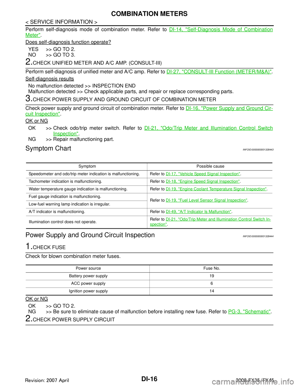
Symptom Possible cause
Speedometer and odo/trip meter indication is malfunctioning. Refer to DI-17, "
Vehicle Speed Signal Inspection".
Tachometer indication is malfunctioning. Refer to DI-18, "
Engine Speed Signal Inspection".
Water temperature gauge indication is malfunctioning. Refer to DI-19, "
Engine Coolant Temperature Signal Inspection".
Fuel gauge indication is malfunctioning. Refer to DI-19, "
Fuel Level Sensor Signal Inspection".
Low-fuel warning lamp indication is irregular.
A/T indicator is malfunctioning. Refer to DI-49, "
A/T Indicator Is Malfunction".
Illumination control does not operate. Refer to
DI-21, "
Odo/Trip Meter and Illumination Control Switch In-
spection".
Power source Fuse No.
Battery power supply 19 ACC power supply 6
Ignition power supply 14
3AA93ABC3ACD3AC03ACA3AC03AC63AC53A913A773A893A873A873A8E3A773A983AC73AC93AC03AC3
3A893A873A873A8F3A773A9D3AAF3A8A3A8C3A863A9D3AAF3A8B3A8C
Page 1144 of 3924

DI-18
< SERVICE INFORMATION >
COMBINATION METERS
2. Check voltage signal between unified meter and A/C amp. har-ness connector M56 terminal 26 and ground.
OK or NG
OK >> GO TO 3.
NG-1 >> If monitor indicates “0 V” constantly, perform the following. 1. Check each unit inputting vehicle speed signal (8 pulse), harness and connector betweeneach unit and unified meter and A/C amp.
2. Repair or replace malfunctioning part.
NG-2 >> If monitor indicates “5 V” or “12 V” constantly, replace unified meter and A/C amp. Refer to DI-32,
"Removal and Installation of Unified Meter and A/C Amp".
3.CHECK CONTINUITY BETWEEN COMBINATION METER AND UNIFIED METER AND A/C AMP.
1. Turn ignition switch OFF.
2. Disconnect combination meter connector and unified meter and A/C amp. connector.
3. Check continuity between combination meter harness connector
M20 terminal 1 and unified meter and A/C amp. harness con-
nector M56 terminal 26.
OK or NG
OK >> Replace combination meter.
NG >> Repair harness or connector.
Engine Speed Signal InspectionINFOID:0000000001328446
Symptom: Tachometer indication is malfunction.
1.CHECK COMBINATION METER INPUT SIGNAL
1. Connect CONSULT-III, and start engine.
2. Select “METER/M&A” on CONSULT-III.
3. Using “TACHO METER” on “Data Monitor”, compare the value of “Data Monitor” with tachometer pointer
of combination meter.
OK or NG
OK >> GO TO 2.
NG >> Replace combination meter.
2.CHECK UNIFIED METER AND A/C AMP. INPUT SIGNAL
Select “Data Monitor” of CONSULT-III to compare values between “ ENG SPEED” of “ENGINE” and “TACHO
METER” of “METER/M&A”.
OK or NG
OK >> Perform self-diagnosis of ECM. Refer to EC-117, "CONSULT-III Function (ENGINE)" (VQ35DE)
or EC-695, "
CONSULT-III Function (ENGINE)" (VK45DE).
NG >> Replace unified meter and A/C amp. Refer to DI-32, "
Removal and Installation of Unified Meter
and A/C Amp".
26 – Ground:
NOTE:
Maximum voltage may be 5 V due to
specifications (connected units).
SKIB0338E
PKIA1935E
1 – 26 : Continuity should exist.
SKIB0343E
3AA93ABC3ACD3AC03ACA3AC03AC63AC53A913A773A893A873A873A8E3A773A983AC73AC93AC03AC3
3A893A873A873A8F3A773A9D3AAF3A8A3A8C3A863A9D3AAF3A8B3A8C
Page 1145 of 3924
COMBINATION METERSDI-19
< SERVICE INFORMATION >
C
DE
F
G H
I
J
L
M A
B
DI
N
O P
Engine Coolant Temperature Signal InspectionINFOID:0000000001328447
Symptom: Water temperature gauge indication is malfunction.
1.CHECK COMBINATION METER INPUT SIGNAL
1. Connect CONSULT-III, and start engine.
2. Select “METER/M&A” on CONSULT-III.
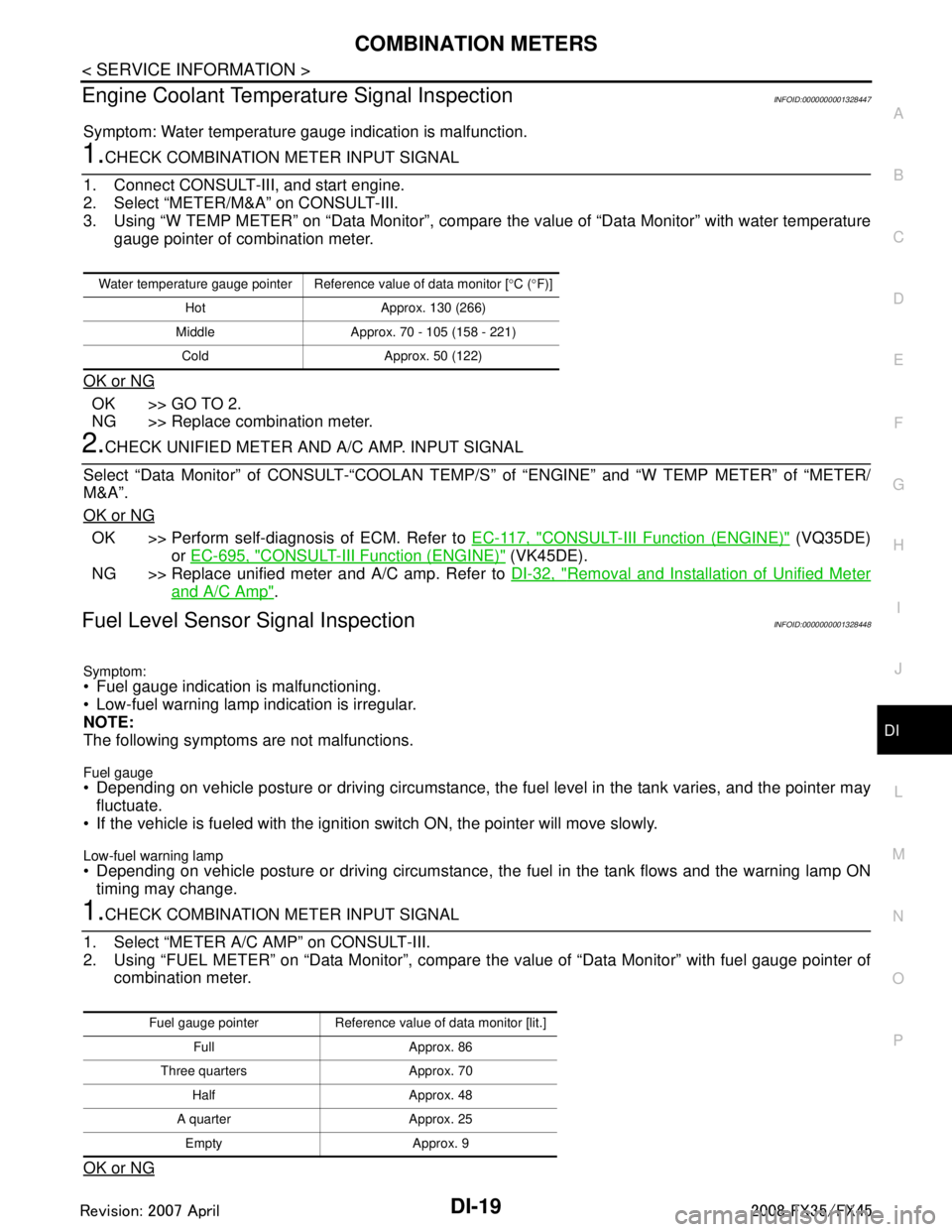
3. Using “W TEMP METER” on “Data Monitor”, compare the value of “Data Monitor” with water temperature
gauge pointer of combination meter.
OK or NG
OK >> GO TO 2.
NG >> Replace combination meter.
2.CHECK UNIFIED METER AND A/C AMP. INPUT SIGNAL
Select “Data Monitor” of CONSULT-“COOLAN TEMP/S ” of “ENGINE” and “W TEMP METER” of “METER/
M&A”.
OK or NG
OK >> Perform self-diagnosis of ECM. Refer to EC-117, "CONSULT-III Function (ENGINE)" (VQ35DE)
or EC-695, "
CONSULT-III Function (ENGINE)" (VK45DE).
NG >> Replace unified meter and A/C amp. Refer to DI-32, "
Removal and Installation of Unified Meter
and A/C Amp".
Fuel Level Sensor Signal InspectionINFOID:0000000001328448
Symptom:
Fuel gauge indication is malfunctioning.
Low-fuel warning lamp indication is irregular.
NOTE:
The following symptoms are not malfunctions.
Fuel gauge Depending on vehicle posture or driving circumstance, the fuel level in the tank varies, and the pointer may
fluctuate.
If the vehicle is fueled with the ignition switch ON, the pointer will move slowly.
Low-fuel warning lamp
Depending on vehicle posture or driving circumstance, t he fuel in the tank flows and the warning lamp ON
timing may change.
1.CHECK COMBINATION METER INPUT SIGNAL
1. Select “METER A/C AMP” on CONSULT-III.
2. Using “FUEL METER” on “Data Monitor”, compare t he value of “Data Monitor” with fuel gauge pointer of
combination meter.
OK or NG
Water temperature gauge pointer Reference value of data monitor [ °C ( °F)]
Hot Approx. 130 (266)
Middle Approx. 70 - 105 (158 - 221) Cold Approx. 50 (122)
Fuel gauge pointer Reference value of data monitor [lit.] Full Approx. 86
Three quarters Approx. 70 Half Approx. 48
A quarter Approx. 25 Empty Approx. 9
3AA93ABC3ACD3AC03ACA3AC03AC63AC53A913A773A893A873A873A8E3A773A983AC73AC93AC03AC3
3A893A873A873A8F3A773A9D3AAF3A8A3A8C3A863A9D3AAF3A8B3A8C
Page 1170 of 3924
DI-44
< SERVICE INFORMATION >
WARNING LAMPS
2.CHECK IPDM E/R INPUT SIGNAL
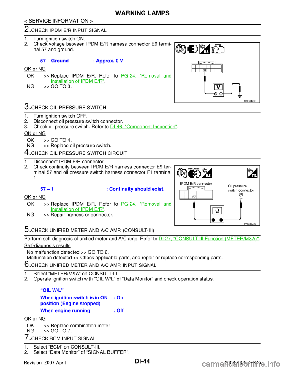
1. Turn ignition switch ON.
2. Check voltage between IPDM E/R harness connector E9 termi- nal 57 and ground.
OK or NG
OK >> Replace IPDM E/R. Refer to PG-24, "Removal and
Installation of IPDM E/R".
NG >> GO TO 3.
3.CHECK OIL PRESSURE SWITCH
1. Turn ignition switch OFF.
2. Disconnect oil pressure switch connector.
3. Check oil pressure switch. Refer to DI-46, "
Component Inspection".
OK or NG
OK >> GO TO 4.
NG >> Replace oil pressure switch.
4.CHECK OIL PRESSURE SWITCH CIRCUIT
1. Disconnect IPDM E/R connector.
2. Check continuity between IPDM E/R harness connector E9 ter- minal 57 and oil pressure switch harness connector F1 terminal
1.
OK or NG
OK >> Replace IPDM E/R. Refer to PG-24, "Removal and
Installation of IPDM E/R".
NG >> Repair harness or connector.
5.CHECK UNIFIED METER AND A/C AMP. (CONSULT-III)
Perform self-diagnosis of unified meter and A/C amp. Refer to DI-27, "
CONSULT-III Function (METER/M&A)".
Self-diagnosis results
No malfunction detected >> GO TO 6.
Malfunction detected >> Check applicable parts, and repair or replace corresponding parts.
6.CHECK UNIFIED METER AND A/C AMP. INPUT SIGNAL
1. Select “METER/M&A” on CONSULT-III.
2. Operate ignition switch with “OIL W/L” of “Data Monitor” and check operation status.
OK or NG
OK >> Replace combination meter.
NG >> GO TO 7.
7.CHECK BCM INPUT SIGNAL
1. Select “BCM” on CONSULT-III.
2. Select “Data Monitor” of “SIGNAL BUFFER”. 57 – Ground : Approx. 0 V
SKIB6449E
57 – 1 : Continuity should exist.
PKIB3572E
“OIL W/L”
When ignition switch is in ON
position (Engine stopped)
: On
When engine running : Off
3AA93ABC3ACD3AC03ACA3AC03AC63AC53A913A773A893A873A873A8E3A773A983AC73AC93AC03AC3
3A893A873A873A8F3A773A9D3AAF3A8A3A8C3A863A9D3AAF3A8B3A8C
Page 1171 of 3924
WARNING LAMPSDI-45
< SERVICE INFORMATION >
C
DE
F
G H
I
J
L
M A
B
DI
N
O P
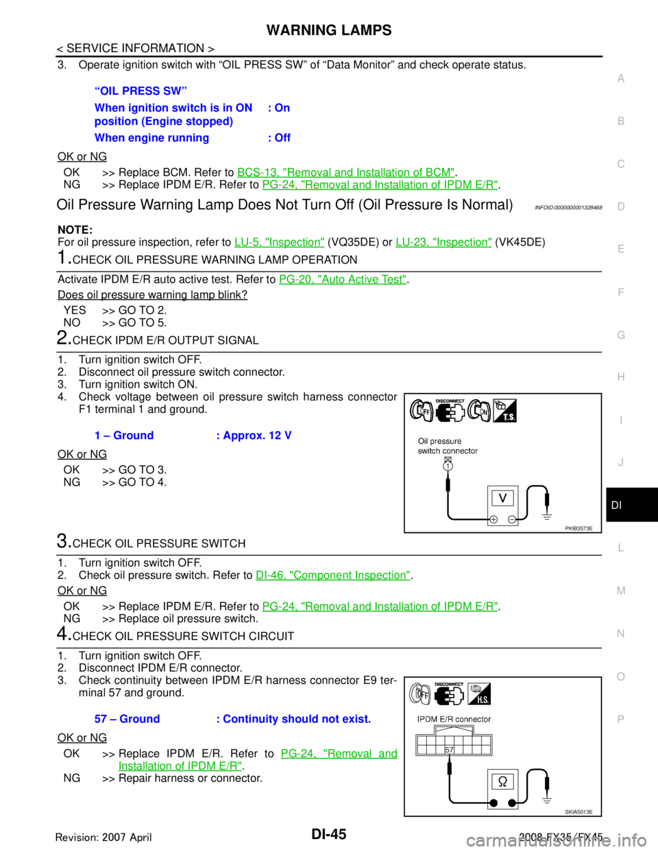
3. Operate ignition switch with “OIL PRESS SW ” of “Data Monitor” and check operate status.
OK or NG
OK >> Replace BCM. Refer to BCS-13, "Removal and Installation of BCM".
NG >> Replace IPDM E/R. Refer to PG-24, "
Removal and Installation of IPDM E/R".
Oil Pressure Warning Lamp Does Not Turn Off (Oil Pressure Is Normal)INFOID:0000000001328468
NOTE:
For oil pressure inspection, refer to LU-5, "
Inspection" (VQ35DE) or LU-23, "Inspection" (VK45DE)
1.CHECK OIL PRESSURE WARNING LAMP OPERATION
Activate IPDM E/R auto active test. Refer to PG-20, "
Auto Active Test".
Does oil pressure warning lamp blink?
YES >> GO TO 2.
NO >> GO TO 5.
2.CHECK IPDM E/R OUTPUT SIGNAL
1. Turn ignition switch OFF.
2. Disconnect oil pressure switch connector.
3. Turn ignition switch ON.
4. Check voltage between oil pressure switch harness connector F1 terminal 1 and ground.
OK or NG
OK >> GO TO 3.
NG >> GO TO 4.
3.CHECK OIL PRESSURE SWITCH
1. Turn ignition switch OFF.
2. Check oil pressure switch. Refer to DI-46, "
Component Inspection".
OK or NG
OK >> Replace IPDM E/R. Refer to PG-24, "Removal and Installation of IPDM E/R".
NG >> Replace oil pressure switch.
4.CHECK OIL PRESSURE SWITCH CIRCUIT
1. Turn ignition switch OFF.
2. Disconnect IPDM E/R connector.
3. Check continuity between IPDM E/R harness connector E9 ter- minal 57 and ground.
OK or NG
OK >> Replace IPDM E/R. Refer to PG-24, "Removal and
Installation of IPDM E/R".
NG >> Repair harness or connector. “OIL PRESS SW”
When ignition switch is in ON
position (Engine stopped)
: On
When engine running : Off
1 – Ground : Approx. 12 V
PKIB3573E
57 – Ground : Continuity should not exist.
SKIA5013E
3AA93ABC3ACD3AC03ACA3AC03AC63AC53A913A773A893A873A873A8E3A773A983AC73AC93AC03AC3
3A893A873A873A8F3A773A9D3AAF3A8A3A8C3A863A9D3AAF3A8B3A8C
Page 1197 of 3924
LANE DEPARTURE WARNING SYSTEMDI-71
< SERVICE INFORMATION >
C
DE
F
G H
I
J
L
M A
B
DI
N
O P
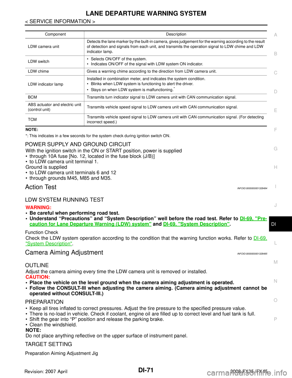
NOTE:
*: This indicates in a few seconds for the system check during ignition switch ON.
POWER SUPPLY AND GROUND CIRCUIT
With the ignition switch in the ON or START position, power is supplied
through 10A fuse [No. 12, located in the fuse block (J/B)]
to LDW camera unit terminal 1.
Ground is supplied
to LDW camera unit terminals 6 and 12
through grounds M45, M85 and M35.
Action TestINFOID:0000000001328494
LDW SYSTEM RUNNING TEST
WARNING:
Be careful when performing road test.
Understand “Precautions” and “System Description” well before the road test. Refer to DI-69, "
Pre-
caution for Lane Departure Warning (LDW) system" and DI-69, "System Description".
Function Check
Check the LDW system operation according to the c ondition that the warning function works. Refer to DI-69,
"System Description".
Camera Aiming AdjustmentINFOID:0000000001328495
OUTLINE
Adjust the camera aiming every time the LDW camera unit is removed or installed.
CAUTION:
Place the vehicle on the level ground when the camera aiming adjustment is operated.
Follow the CONSULT-III when ad justing the camera aiming. (Camera aiming adjustment cannot be
operated without CONSULT-III.)
PREPARATION
Keep all tires inflated to correct pressures. Adjust the tire pressure to the specified pressure value.
There is no-load in vehicle. Check if coolant, engine oil are filled up to correct level and fuel tank is full.
Shift the gear into “P” position and release the parking brake.
Clean the windshield.
NOTE:
Do not place anything reflective on t he upper surface of instrument panel.
TARGET SETTING
Preparation Aiming Adjustment Jig
Component Description
LDW camera unit Detects the lane marker by the built-in camera, gives judgement for the warning according to the result
of detection and signals from each unit, and transmits the operation signal to LDW chime and LDW
indicator lamp.
LDW switch Selects ON/OFF of the system.
Indicates ON/OFF of the signal with LDW system ON indicator.
LDW chime Gives a warning chime according to the direction from LDW camera unit.
LDW indicator lamp Installed in combination meter, and indicates the system condition.
Blinks when LDW system is functioning to alert the driver.
Stays on when LDW system is malfunctioning.
*
BCM Transmits turn indicator signal to LDW camera unit with CAN communication signal.
ABS actuator and electric unit
(control unit)
Transmits vehicle speed signal to LDW camera unit with CAN communication signal.
TCM Transmits vehicle speed signal to LDW camera unit with CAN communication signal. (For detecting
incorrect speed.)
3AA93ABC3ACD3AC03ACA3AC03AC63AC53A913A773A893A873A873A8E3A773A983AC73AC93AC03AC3
3A893A873A873A8F3A773A9D3AAF3A8A3A8C3A863A9D3AAF3A8B3A8C