2008 INFINITI FX35 checking oil
[x] Cancel search: checking oilPage 3106 of 3924
LT-4
< SERVICE INFORMATION >
PRECAUTIONS
SERVICE INFORMATION
PRECAUTIONS
Precaution for Supplemental Restraint System (SRS) "AIR BAG" and "SEAT BELT
PRE-TENSIONER"
INFOID:0000000001612924
The Supplemental Restraint System such as “A IR BAG” and “SEAT BELT PRE-TENSIONER”, used along
with a front seat belt, helps to reduce the risk or severi ty of injury to the driver and front passenger for certain
types of collision. This system includes seat belt switch inputs and dual stage front air bag modules. The SRS
system uses the seat belt switches to determine the front air bag deployment, and may only deploy one front
air bag, depending on the severity of a collision and w hether the front occupants are belted or unbelted.
Information necessary to service the system safely is included in the “SUPPLEMENTAL RESTRAINT SYS-
TEM” and “SEAT BELTS” of this Service Manual.
WARNING:
• To avoid rendering the SRS inopera tive, which could increase the risk of personal injury or death in
the event of a collision which would result in air bag inflation, all maintenance must be performed by
an authorized NISS AN/INFINITI dealer.
Improper maintenance, including in correct removal and installation of the SRS, can lead to personal
injury caused by unintent ional activation of the system. For re moval of Spiral Cable and Air Bag
Module, see the “SUPPLEMEN TAL RESTRAINT SYSTEM”.
Do not use electrical test equipmen t on any circuit related to the SRS unless instructed to in this
Service Manual. SRS wiring harnesses can be identi fied by yellow and/or orange harnesses or har-
ness connectors.
General Precaution for Service OperationINFOID:0000000001328264
Never work with wet hands.
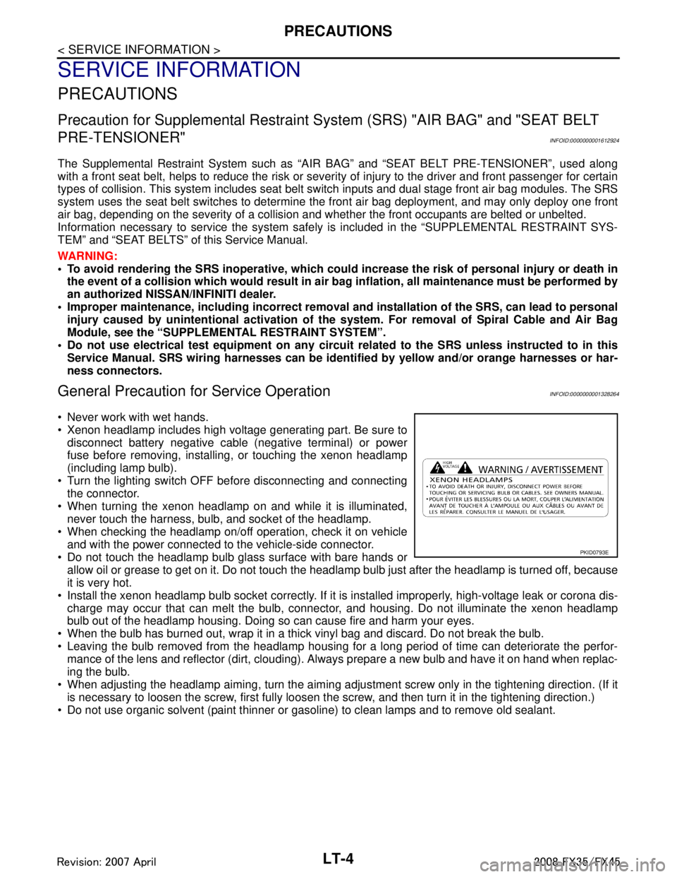
Xenon headlamp includes high voltage generating part. Be sure to disconnect battery negative cable (negative terminal) or power
fuse before removing, installing, or touching the xenon headlamp
(including lamp bulb).
Turn the lighting switch OFF before disconnecting and connecting the connector.
When turning the xenon headlamp on and while it is illuminated, never touch the harness, bulb, and socket of the headlamp.
When checking the headlamp on/off operation, check it on vehicle
and with the power connected to the vehicle-side connector.
Do not touch the headlamp bulb glass surface with bare hands or allow oil or grease to get on it. Do not touch the headl amp bulb just after the headlamp is turned off, because
it is very hot.
Install the xenon headlamp bulb socket co rrectly. If it is installed improperly, high-voltage leak or corona dis-
charge may occur that can melt the bulb, connecto r, and housing. Do not illuminate the xenon headlamp
bulb out of the headlamp housing. Doing so can cause fire and harm your eyes.
When the bulb has burned out, wrap it in a thick vinyl bag and discard. Do not break the bulb.
Leaving the bulb removed from the headlamp housing for a long period of time can deteriorate the perfor- mance of the lens and reflector (dirt, clouding). Al ways prepare a new bulb and have it on hand when replac-
ing the bulb.
When adjusting the headlamp aiming, turn the aiming adjus tment screw only in the tightening direction. (If it
is necessary to loosen the screw, first fully loosen the screw, and then turn it in the tightening direction.)
Do not use organic solvent (paint thinner or gasoline) to clean lamps and to remove old sealant.
PKID0793E
3AA93ABC3ACD3AC03ACA3AC03AC63AC53A913A773A893A873A873A8E3A773A983AC73AC93AC03AC3
3A893A873A873A8F3A773A9D3AAF3A8A3A8C3A863A9D3AAF3A8B3A8C
Page 3290 of 3924
![INFINITI FX35 2008 Service Manual
ENGINE OILLU-5
< SERVICE INFORMATION > [VQ35DE]
C
D
E
F
G H
I
J
K L
M A
LU
NP
O
ENGINE OIL
InspectionINFOID:0000000001325813
ENGINE OIL LEVEL
NOTE:
Before starting engine, put vehicle horizontally an INFINITI FX35 2008 Service Manual
ENGINE OILLU-5
< SERVICE INFORMATION > [VQ35DE]
C
D
E
F
G H
I
J
K L
M A
LU
NP
O
ENGINE OIL
InspectionINFOID:0000000001325813
ENGINE OIL LEVEL
NOTE:
Before starting engine, put vehicle horizontally an](/manual-img/42/57017/w960_57017-3289.png)
ENGINE OILLU-5
< SERVICE INFORMATION > [VQ35DE]
C
D
E
F
G H
I
J
K L
M A
LU
NP
O
ENGINE OIL
InspectionINFOID:0000000001325813
ENGINE OIL LEVEL
NOTE:
Before starting engine, put vehicle horizontally and check
the engine oil level. If engine is already started, stop
it and allow 10 minutes before checking.
1. Pull out oil level gauge and wipe it clean.
2. Insert oil level gauge and make sure the engine oil level is within the range shown in the figure.
3. If it is out of range, adjust it.
NOTE:
When checking the engine oil level, insert oil level gauge with its
tip aligned with oil level gauge guide on cylinder head. (In figure,
air cleaner case and air duct are removed.)
ENGINE OIL APPEARANCE
Check engine oil for white turbidity or heavy contamination.
If engine oil becomes turbid and white, it is highl y probable that it is contaminated with engine coolant.
Repair or replace damaged parts.
ENGINE OIL LEAKAGE
Check for engine oil leakage around the following areas:
Oil pans (lower and upper)
Oil pan drain plug
Oil pressure switch
Oil filter
Oil filter bracket (AWD models)
Oil cooler
Water pump cover
Chain tensioner cover
Intake valve timing control cover and intake valve timing control solenoid valve
Mating surface between cylinder head and rocker cover
Mating surface between front timing chain case and rear timing chain case
Mating surface between rear timing chain case and cylinder head
Mating surface between rear timing chain case and cylinder block
Mating surface between rear timing chain case and oil pan (upper)
Mating surface between cylinder block and cylinder head
Crankshaft oil seals (front and rear)
Camshaft position sensor (PHASE)
OIL PRESSURE CHECK
PBIC3101E
KBIA1343E
3AA93ABC3ACD3AC03ACA3AC03AC63AC53A913A773A893A873A873A8E3A773A983AC73AC93AC03AC3
3A893A873A873A8F3A773A9D3AAF3A8A3A8C3A863A9D3AAF3A8B3A8C
Page 3308 of 3924
![INFINITI FX35 2008 Service Manual
ENGINE OILLU-23
< SERVICE INFORMATION > [VK45DE]
C
D
E
F
G H
I
J
K L
M A
LU
NP
O
ENGINE OIL
InspectionINFOID:0000000001325829
ENGINE OIL LEVEL
NOTE:
Before starting engine, put vehicle horizontally a INFINITI FX35 2008 Service Manual
ENGINE OILLU-23
< SERVICE INFORMATION > [VK45DE]
C
D
E
F
G H
I
J
K L
M A
LU
NP
O
ENGINE OIL
InspectionINFOID:0000000001325829
ENGINE OIL LEVEL
NOTE:
Before starting engine, put vehicle horizontally a](/manual-img/42/57017/w960_57017-3307.png)
ENGINE OILLU-23
< SERVICE INFORMATION > [VK45DE]
C
D
E
F
G H
I
J
K L
M A
LU
NP
O
ENGINE OIL
InspectionINFOID:0000000001325829
ENGINE OIL LEVEL
NOTE:
Before starting engine, put vehicle horizontally and check
the engine oil level. If engine is already started, stop
it and allow 15 minutes before checking.
1. Pull out oil level gauge and wipe it clean.
2. Insert oil level gauge and make sure the engine oil level is within the range shown in the figure.
3. If it is out of range, adjust it.
ENGINE OIL APPEARANCE
Check engine oil for white turbidity or heavy contamination.
If engine oil becomes turbid and white, it is highl y probable that it is contaminated with engine coolant.
Repair or replace damaged parts.
ENGINE OIL LEAKAGE
Check for oil leakage around the following area.
Oil pan
Oil pan drain plug
Oil pressure switch
Oil filter
Oil cooler
Intake valve timing control cover
Intake valve timing control solenoid valve
Front cover
Chain tensioner cover
Mating surface between cylinder block and cylinder head
Mating surface between cylinder head and rocker cover
Crankshaft oil seals (front and rear)
OIL PRESSURE CHECK
WARNING:
Be careful not to burn yoursel f, as engine oil may be hot.
Oil pressure check should be done in “Parking position”.
1. Check the engine oil level. Refer to "ENGINE OIL LEVEL".
2. Remove front engine undercover with power tool.
3. Disconnect harness connector at oil pressure switch, and remove oil pressure switch using deep socket (commercial ser-
vice tool).
CAUTION:
Do not drop or shock oil pressure switch.
PBIC0801E
PBIC1524E
3AA93ABC3ACD3AC03ACA3AC03AC63AC53A913A773A893A873A873A8E3A773A983AC73AC93AC03AC3
3A893A873A873A8F3A773A9D3AAF3A8A3A8C3A863A9D3AAF3A8B3A8C
Page 3318 of 3924
MA-1
MAINTENANCE
C
DE
F
G H
I
J
K
M
SECTION MA
A
B
MA
N
O P
CONTENTS
MAINTENANCE
SERVICE INFORMATION .. ..........................2
PREPARATION .............................................. .....2
Special Service Tool ........................................... ......2
Commercial Service Tool ..........................................2
GENERAL MAINTENANCE ................................3
Explanation of General Maintenance .................. ......3
PERIODIC MAINTENANCE ................................5
Introduction of Periodic Maintenance .................. ......5
Schedule 1 ................................................................5
Schedule 2 ................................................................7
RECOMMENDED FLUIDS AND LUBRI-
CANTS .................................................................
9
Fluids and Lubricants .......................................... ......9
Engine Oil Recommendation ....................................9
Anti-Freeze Coolant Mixture Ratio ..........................10
ENGINE MAINTENANCE (VQ35DE ENGINE) ....11
Checking Drive Belts ........................................... ....11
Drive Belts Tension Adjustment ..............................11
Changing Engine Coolant .......................................12
Checking Fuel Line .................................................15
Changing Air Cleaner Filter .....................................15
Changing Engine Oil ...............................................15
Changing Oil Filter ..................................................16
Changing Spark Plugs (Platinum-Tipped Type) ......17
Checking EVAP Vapor Line ....................................18
ENGINE MAINTENANCE (VK45DE ENGINE) ....19
Checking Drive Belts ........................................... ....19
Tension Adjustment ................................................19
Changing Engine Coolant .......................................19
Checking Fuel Line .............................................. ....22
Changing Air Cleaner Filter .....................................22
Changing Engine Oil ................................................22
Changing Oil Filter ...................................................23
Changing Spark Plugs (Platinum-Tipped Type) ......24
Checking EVAP Vapor Line .....................................25
CHASSIS AND BODY MAINTENANCE ...........26
Checking Exhaust System ................................... ....26
Checking A/T Fluid ..................................................26
Changing A/T Fluid ..................................................27
Checking Transfer Fluid ..........................................28
Changing Transfer Fluid ..........................................28
Checking Propeller Shaft .........................................29
Checking Differential Gear Oil .................................29
Changing Differential Gear Oil .................................29
Balancing Wheels (Bonding Weight Type) ..............30
Tire Rotation ............................................................31
Checking Brake Fluid Level and Leaks ...................32
Checking Brake Line and Cables ............................32
Changing Brake Fluid ..............................................32
Checking Disc Brake ...............................................32
Checking Steering Gear and Linkage ......................33
Checking Power Steering Fluid and Line ................33
Axle and Suspension Parts .....................................34
Drive Shaft ...............................................................34
Lubricating Locks, Hinges and Hood Latch .............35
Checking Seat Belt, Buckles, Retractors, Anchors
and Adjusters ...........................................................
35
SERVICE DATA AND SPECIFICATIONS
(SDS) .................................................................
37
Standard and Limit ..................................................37
3AA93ABC3ACD3AC03ACA3AC03AC63AC53A913A773A893A873A873A8E3A773A983AC73AC93AC03AC3
3A893A873A873A8F3A773A9D3AAF3A8A3A8C3A863A9D3AAF3A8B3A8C
Page 3319 of 3924
MA-2
< SERVICE INFORMATION >
PREPARATION
SERVICE INFORMATION
PREPARATION
Special Service ToolINFOID:0000000001328891
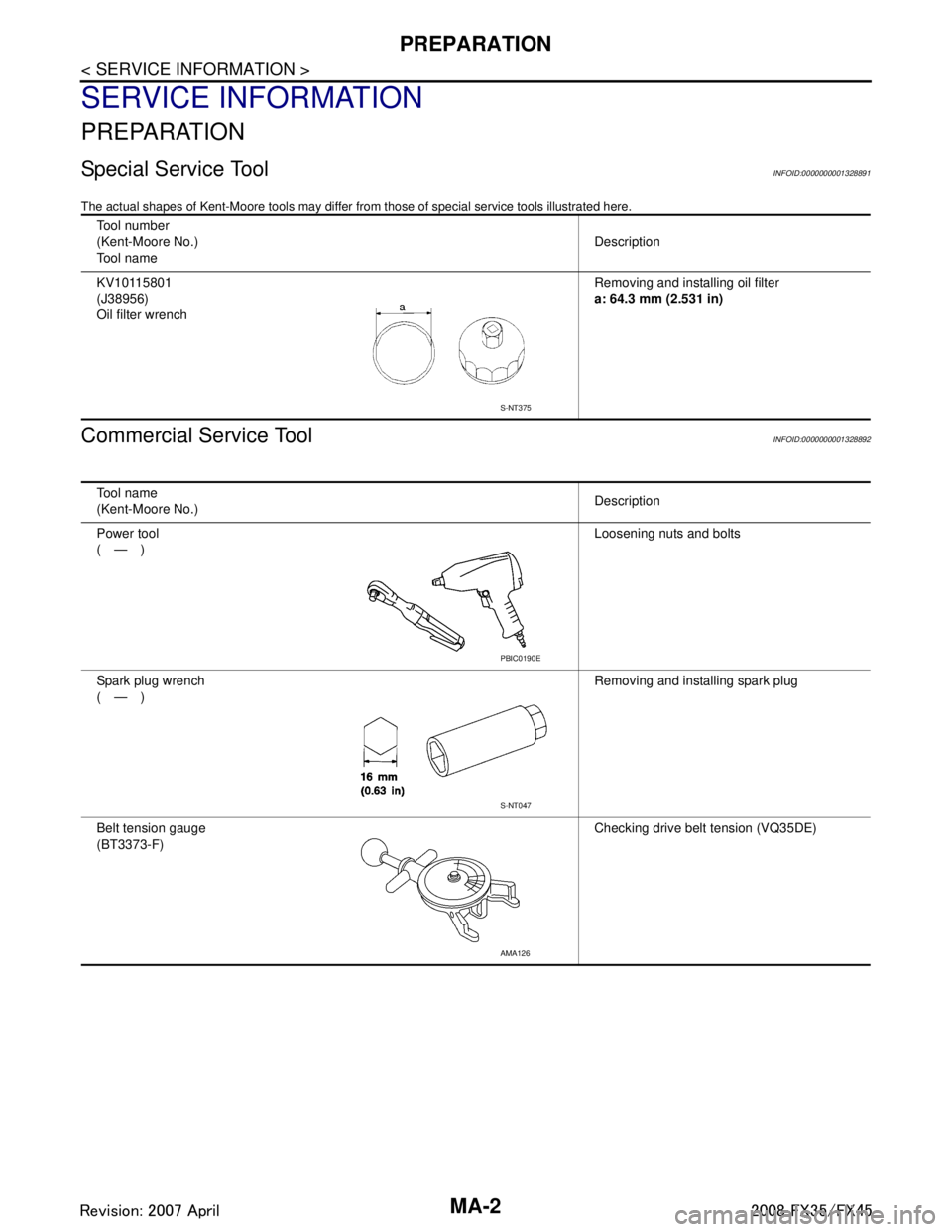
The actual shapes of Kent-Moore tools may differ from those of special service tools illustrated here.
Commercial Service ToolINFOID:0000000001328892
Tool number
(Kent-Moore No.)
Tool name Description
KV10115801
(J38956)
Oil filter wrench Removing and installing oil filter
a: 64.3 mm (2.531 in)
S-NT375
Tool name
(Kent-Moore No.)
Description
Power tool
(—) Loosening nuts and bolts
Spark plug wrench
(—) Removing and installing spark plug
Belt tension gauge
(BT3373-F) Checking drive belt tension (VQ35DE)
PBIC0190E
S-NT047
AMA126
3AA93ABC3ACD3AC03ACA3AC03AC63AC53A913A773A893A873A873A8E3A773A983AC73AC93AC03AC3
3A893A873A873A8F3A773A9D3AAF3A8A3A8C3A863A9D3AAF3A8B3A8C
Page 3328 of 3924
ENGINE MAINTENANCE (VQ35DE ENGINE)MA-11
< SERVICE INFORMATION >
C
DE
F
G H
I
J
K
M A
B
MA
N
O P
ENGINE MAINTENANCE (VQ35DE ENGINE)
Checking Drive BeltsINFOID:0000000001328900
WARNING:
Be sure to perform when engine is stopped.
1. Inspect belts for cracks, fraying, wear and oil. If necessary, replace.
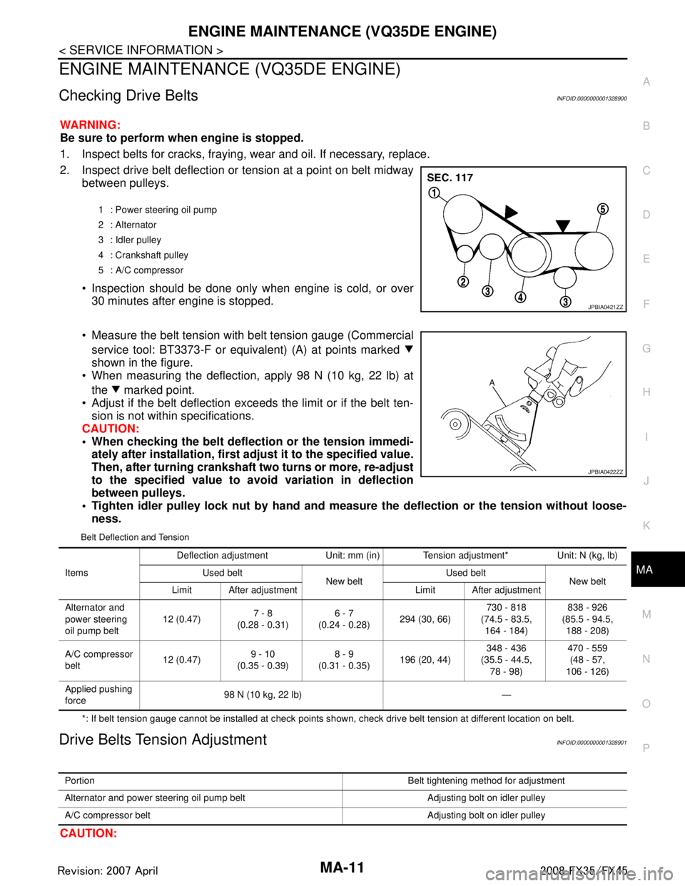
2. Inspect drive belt deflection or tension at a point on belt midway
between pulleys.
Inspection should be done only when engine is cold, or over 30 minutes after engine is stopped.
Measure the belt tension with belt tension gauge (Commercial service tool: BT3373-F or equivalent) (A) at points marked
shown in the figure.
When measuring the deflection, apply 98 N (10 kg, 22 lb) at
the marked point.
Adjust if the belt deflection exceeds the limit or if the belt ten- sion is not within specifications.
CAUTION:
• When checking the belt deflect ion or the tension immedi-
ately after installation, first ad just it to the specified value.
Then, after turning crankshaft two turns or more, re-adjust
to the specified value to avo id variation in deflection
between pulleys.
Tighten idler pulley lock nut by hand and measure the deflection or the tension without loose-
ness.
Belt Deflection and Tension
*: If belt tension gauge cannot be installed at check points shown, check drive belt tension at different location on belt.
Drive Belts Tension AdjustmentINFOID:0000000001328901
CAUTION:
1 : Power steering oil pump
2 : Alternator
3 : Idler pulley
4 : Crankshaft pulley
5 : A/C compressor
JPBIA0421ZZ
JPBIA0422ZZ
Items Deflection adjustment Unit: mm (in) Tension adjustment* Unit: N (kg, lb)
Used belt New beltUsed belt
New belt
Limit After adjustment Limit After adjustment
Alternator and
power steering
oil pump belt 12 (0.47)
7 - 8
(0.28 - 0.31) 6 - 7
(0.24 - 0.28) 294 (30, 66) 730 - 818
(74.5 - 83.5, 164 - 184) 838 - 926
(85.5 - 94.5, 188 - 208)
A/C compressor
belt 12 (0.47)9 - 10
(0.35 - 0.39) 8 - 9
(0.31 - 0.35) 196 (20, 44) 348 - 436
(35.5 - 44.5, 78 - 98) 470 - 559
(48 - 57,
106 - 126)
Applied pushing
force 98 N (10 kg, 22 lb) —
Portion
Belt tightening method for adjustment
Alternator and power steering oil pump belt Adjusting bolt on idler pulley
A/C compressor belt Adjusting bolt on idler pulley
3AA93ABC3ACD3AC03ACA3AC03AC63AC53A913A773A893A873A873A8E3A773A983AC73AC93AC03AC3
3A893A873A873A8F3A773A9D3AAF3A8A3A8C3A863A9D3AAF3A8B3A8C
Page 3329 of 3924
MA-12
< SERVICE INFORMATION >
ENGINE MAINTENANCE (VQ35DE ENGINE)
When belt is replaced with a new one, adjust it to value for “New belt” to accommodate for insuffi-
cient adaptability with pulley grooves.
When deflection or tension of belt being used exceeds “Limit”, adjust it to value for “After adjust-
ment”.
When checking belt deflection or te nsion immediately after installation, first adjust it to the specified
value. Then, after turning crankshaft two turns or mo re, re-adjust to the specified value to avoid vari-
ation in deflection between pulleys.
When installing belt, make sure that it is correctly engaged with pulley grooves.
Keep engine oil, working fluid and engine coolant away from belt and pulley grooves.
Do not twist or bend belt excessively.
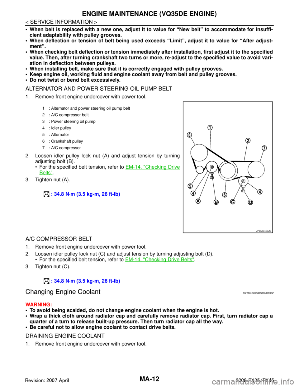
ALTERNATOR AND POWER STEERING OIL PUMP BELT
1. Remove front engine undercover with power tool.
2. Loosen idler pulley lock nut (A) and adjust tension by turning adjusting bolt (B).
For the specified belt tension, refer to EM-14, "
Checking Drive
Belts".
3. Tighten nut (A).
A/C COMPRESSOR BELT
1. Remove front engine undercover with power tool.
2. Loosen idler pulley lock nut (C) and adjust tension by turning adjusting bolt (D). For the specified belt tension, refer to EM-14, "
Checking Drive Belts".
3. Tighten nut (C).
Changing Engine CoolantINFOID:0000000001328902
WARNING:
To avoid being scalded, do not change en gine coolant when the engine is hot.
Wrap a thick cloth around radiator cap and carefully remove radiator cap. First, turn radiator cap a
quarter of a turn to release built-up pressu re. Then turn radiator cap all the way.
Be careful not to allow engine coolant to contact drive belts.
DRAINING ENGINE COOLANT
1. Remove front engine undercover with power tool.
1 : Alternator and power steering oil pump belt
2: A/C compressor belt
3 : Power steering oil pump
4 : Idler pulley
5 : Alternator
6 : Crankshaft pulley
7: A/C compressor
: 34.8 N·m (3.5 kg-m, 26 ft-lb)
JPBIA0423ZZ
: 34.8 N·m (3.5 kg-m, 26 ft-lb)
3AA93ABC3ACD3AC03ACA3AC03AC63AC53A913A773A893A873A873A8E3A773A983AC73AC93AC03AC3
3A893A873A873A8F3A773A9D3AAF3A8A3A8C3A863A9D3AAF3A8B3A8C
Page 3332 of 3924
ENGINE MAINTENANCE (VQ35DE ENGINE)MA-15
< SERVICE INFORMATION >
C
DE
F
G H
I
J
K
M A
B
MA
N
O P
4. Run the engine and warm it up to normal operating temperature.
5. Rev engine two or three times under no-load.
6. Stop the engine and wait until it cools down.
7. Drain water from the system. Refer to CO-10, "
Changing Engine Coolant".
8. Repeat steps 1 through 7 until clear water begins to drain from radiator.
Checking Fuel LineINFOID:0000000001328903
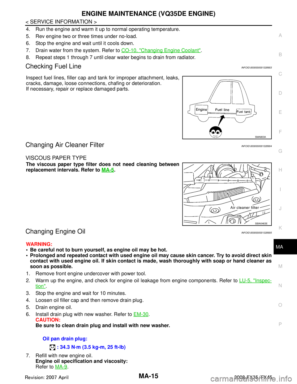
Inspect fuel lines, filler cap and tank for improper attachment, leaks,
cracks, damage, loose connections , chafing or deterioration.
If necessary, repair or replace damaged parts.
Changing Air Cleaner FilterINFOID:0000000001328904
VISCOUS PAPER TYPE
The viscous paper type filter does not need cleaning between
replacement intervals. Refer to MA-5
.
Changing Engine OilINFOID:0000000001328905
WARNING:
Be careful not to burn yoursel f, as engine oil may be hot.
Prolonged and repeated contact with used engine oil may cause skin cancer. Try to avoid direct skin
contact with used engine oil. If skin contact is made, wash thorough ly with soap or hand cleaner as
soon as possible.
1. Remove front engine undercover with power tool.
2. Warm up the engine, and check for engine oil leakage from engine components. Refer to LU-5, "
Inspec-
tion".
3. Stop the engine and wait for 10 minutes.
4. Loosen oil filler cap and then remove drain plug.
5. Drain engine oil.
6. Install drain plug with new washer. Refer to EM-30
.
CAUTION:
Be sure to clean drain plug and install with new washer.
7. Refill with new engine oil. Engine oil specificat ion and viscosity:
Refer to MA-9
.
SMA803A
SBIA0463E
Oil pan drain plug:
: 34.3 N·m (3.5 kg-m, 25 ft-lb)
3AA93ABC3ACD3AC03ACA3AC03AC63AC53A913A773A893A873A873A8E3A773A983AC73AC93AC03AC3
3A893A873A873A8F3A773A9D3AAF3A8A3A8C3A863A9D3AAF3A8B3A8C