2008 INFINITI FX35 brake light
[x] Cancel search: brake lightPage 3188 of 3924
LT-86
< SERVICE INFORMATION >
TURN SIGNAL AND HAZARD WARNING LAMPS
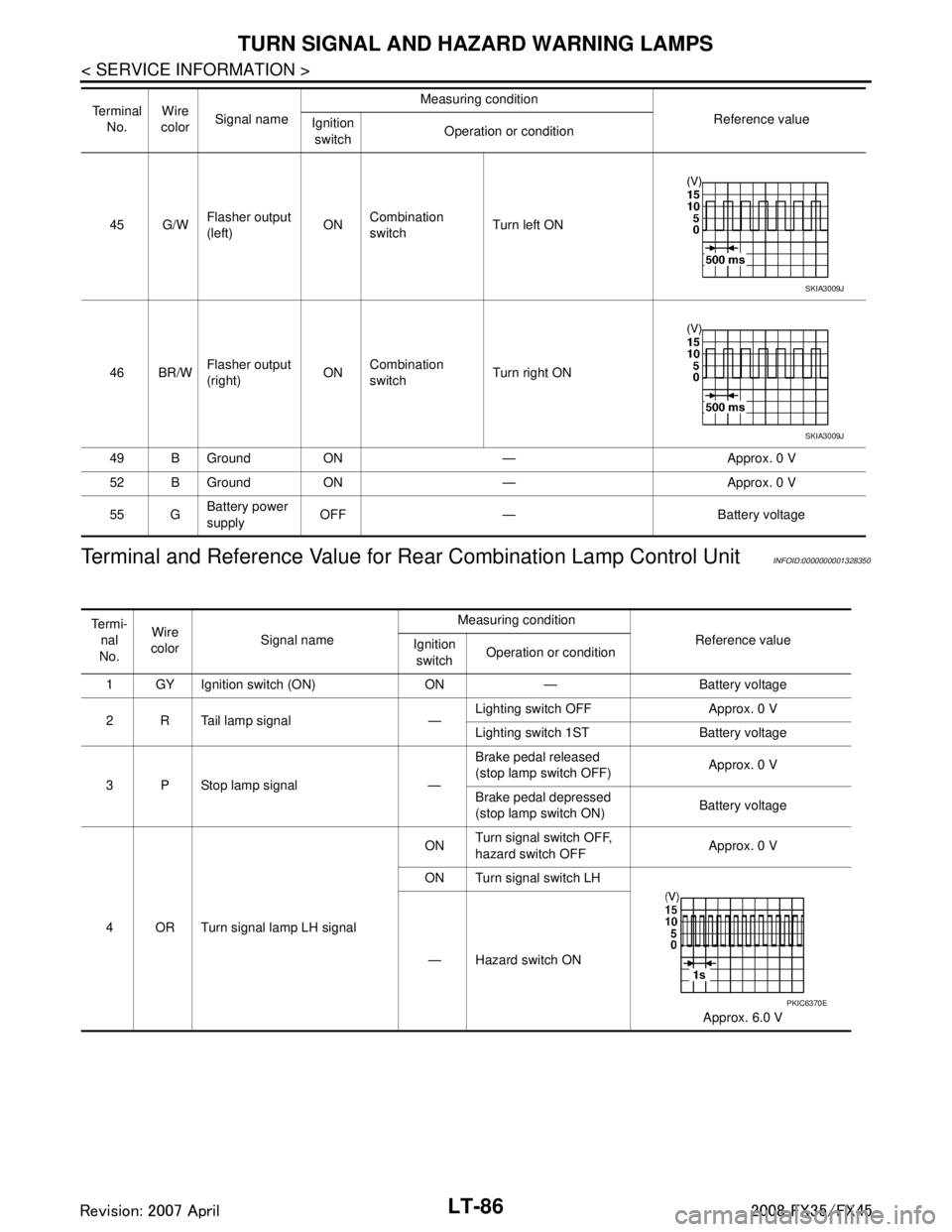
Terminal and Reference Value for Re ar Combination Lamp Control Unit
INFOID:0000000001328350
45 G/WFlasher output
(left) ON
Combination
switch Turn left ON
46 BR/W Flasher output
(right) ONCombination
switch Turn right ON
49 B Ground ON — Approx. 0 V
52 B Ground ON — Approx. 0 V
55 G Battery power
supply OFF — Battery voltage
Te r m i n a l
No. Wire
color Signal name Measuring condition
Reference value
Ignition
switch Operation or condition
SKIA3009J
SKIA3009J
Te r m i -
nal
No. Wire
color Signal name Measuring condition
Reference value
Ignition
switch Operation or condition
1 GY Ignition switch (ON) ON — Battery voltage
2 R Tail lamp signal — Lighting switch OFF Approx. 0 V
Lighting switch 1ST Battery voltage
3 P Stop lamp signal — Brake pedal released
(stop lamp switch OFF)
Approx. 0 V
Brake pedal depressed
(stop lamp switch ON) Battery voltage
4 OR Turn signal lamp LH signal ON
Turn signal switch OFF,
hazard switch OFF
Approx. 0 V
ON Turn signal switch LH
Approx. 6.0 V
— Hazard switch ON
PKIC6370E
3AA93ABC3ACD3AC03ACA3AC03AC63AC53A913A773A893A873A873A8E3A773A983AC73AC93AC03AC3
3A893A873A873A8F3A773A9D3AAF3A8A3A8C3A863A9D3AAF3A8B3A8C
Page 3189 of 3924
TURN SIGNAL AND HAZARD WARNING LAMPSLT-87
< SERVICE INFORMATION >
C
DE
F
G H
I
J
L
M A
B
LT
N
O P
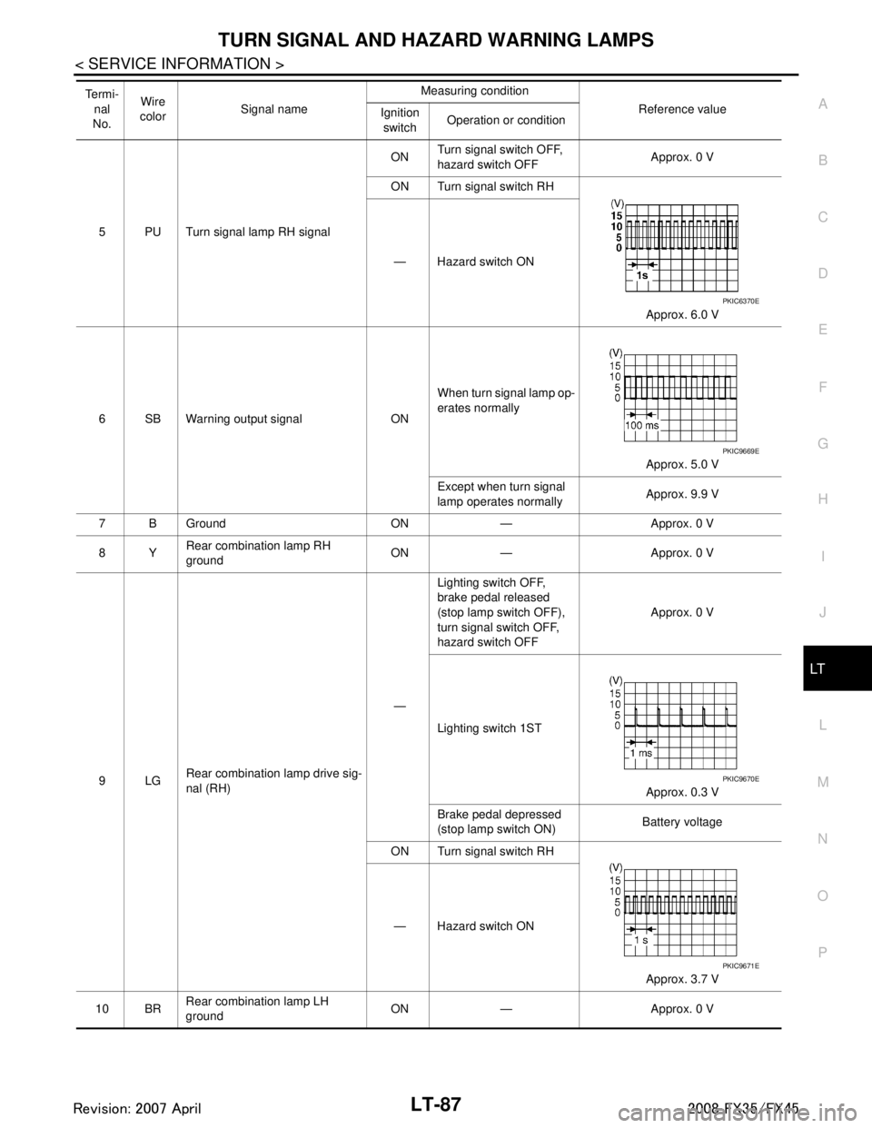
5 PU Turn signal lamp RH signal ON
Turn signal switch OFF,
hazard switch OFF
Approx. 0 V
ON Turn signal switch RH
Approx. 6.0 V
— Hazard switch ON
6 SB Warning output signal ON When turn signal lamp op-
erates normally
Approx. 5.0 V
Except when turn signal
lamp operates normally Approx. 9.9 V
7 B Ground ON — Approx. 0 V
8Y Rear combination lamp RH
ground ON — Approx. 0 V
9LG Rear combination lamp drive sig-
nal (RH) —Lighting switch OFF,
brake pedal released
(stop lamp switch OFF),
turn signal switch OFF,
hazard switch OFF
Approx. 0 V
Lighting switch 1ST Approx. 0.3 V
Brake pedal depressed
(stop lamp switch ON) Battery voltage
ON Turn signal switch RH
Approx. 3.7 V
— Hazard switch ON
10 BR Rear combination lamp LH
ground
ON — Approx. 0 V
Te r m i -
nal
No. Wire
color Signal name Measuring condition
Reference value
Ignition
switch Operation or condition
PKIC6370E
PKIC9669E
PKIC9670E
PKIC9671E
3AA93ABC3ACD3AC03ACA3AC03AC63AC53A913A773A893A873A873A8E3A773A983AC73AC93AC03AC3
3A893A873A873A8F3A773A9D3AAF3A8A3A8C3A863A9D3AAF3A8B3A8C
Page 3190 of 3924
LT-88
< SERVICE INFORMATION >
TURN SIGNAL AND HAZARD WARNING LAMPS
How to Proceed with Trouble Diagnosis
INFOID:0000000001328351
1. Confirm the symptom or customer complaint.
2. Understand operation description and function description. Refer to LT-78, "
System Description".
3. Perform preliminary check. Refer to LT-88, "
Preliminary Check".
4. Check symptom and repair or r eplace the cause of malfunction.
5. Do turn signal and hazard warning lamps operate no rmally? If YES, GO TO 6. If NO, GO TO 4.
6. INSPECTION END
Preliminary CheckINFOID:0000000001328352
CHECK POWER SUPPLY AND GROUND CIRCUIT
1.CHECK FUSES
Check for blown fuses.
Refer to LT- 8 2 , "Wiring Diagram - TURN -".
OK or NG
OK >> GO TO 2.
NG >> If fuse is blown, be sure to eliminate caus e of malfunction before installing new fuse. Refer to PG-
3.
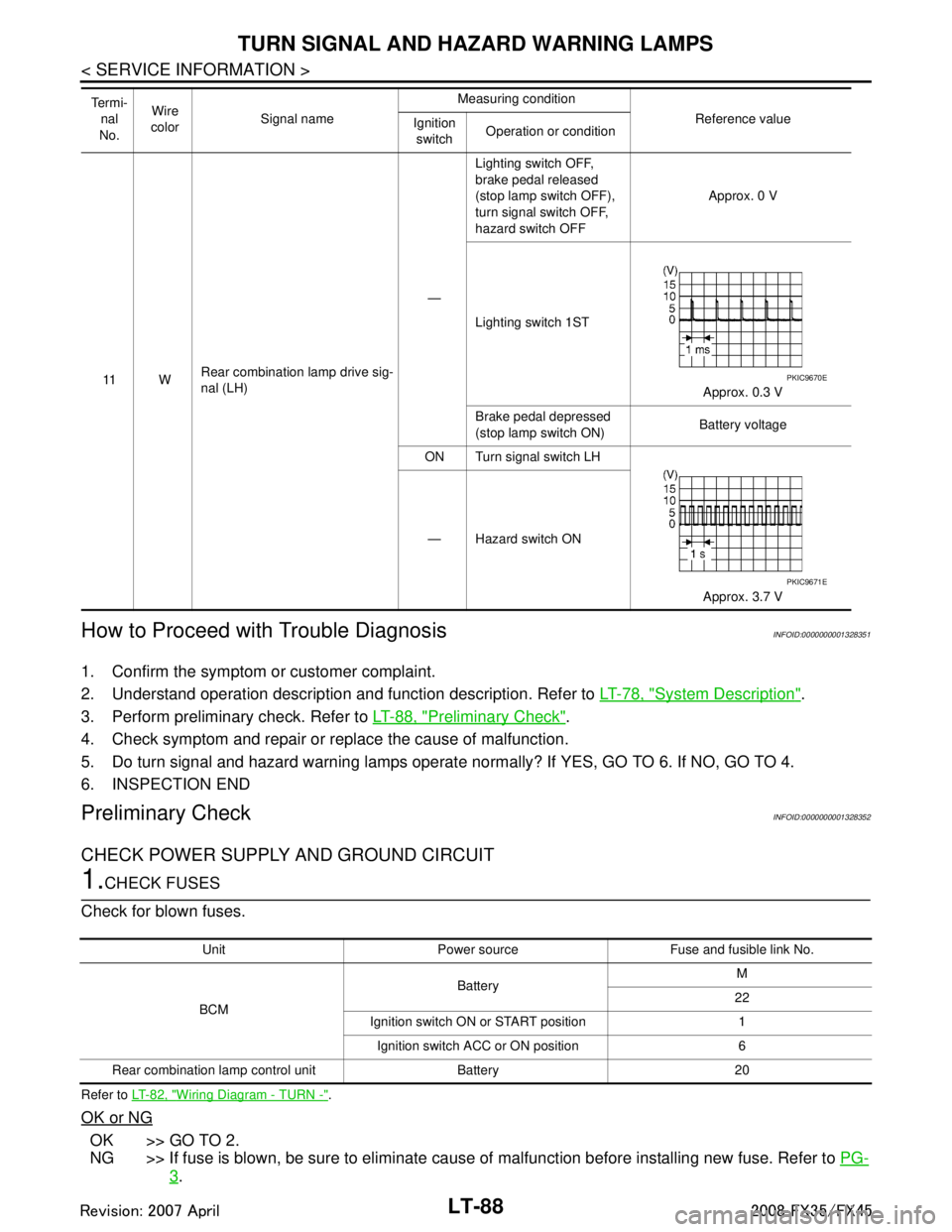
11 WRear combination lamp drive sig-
nal (LH) —Lighting switch OFF,
brake pedal released
(stop lamp switch OFF),
turn signal switch OFF,
hazard switch OFF
Approx. 0 V
Lighting switch 1ST Approx. 0.3 V
Brake pedal depressed
(stop lamp switch ON) Battery voltage
ON Turn signal switch LH
Approx. 3.7 V
— Hazard switch ON
Te r m i -
nal
No. Wire
color Signal name Measuring condition
Reference value
Ignition
switch Operation or conditionPKIC9670E
PKIC9671E
Unit Power source Fuse and fusible link No.
BCM Battery
M
22
Ignition switch ON or START position 1 Ignition switch ACC or ON position 6
Rear combination lamp control unit Battery 20
3AA93ABC3ACD3AC03ACA3AC03AC63AC53A913A773A893A873A873A8E3A773A983AC73AC93AC03AC3
3A893A873A873A8F3A773A9D3AAF3A8A3A8C3A863A9D3AAF3A8B3A8C
Page 3192 of 3924
LT-90
< SERVICE INFORMATION >
TURN SIGNAL AND HAZARD WARNING LAMPS
ACTIVE TEST
Display Item List
Turn Signal Lamp Does Not OperateINFOID:0000000001381753
1.CHECK BULB
Check bulb standard of each turn signal lamp is correct.
OK or NG
OK >> GO TO 2.
NG >> Replace turn signal lamp bulb.
2.CHECK COMBINATION SWITCH INPUT SIGNAL
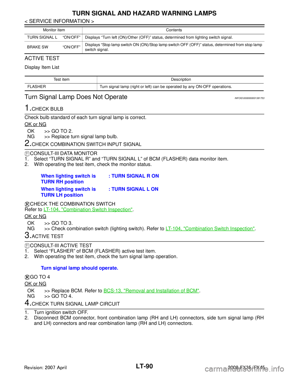
CONSULT-III DATA MONITOR
1. Select “TURN SIGNAL R” and “TURN SIGNAL L” of BCM (FLASHER) data monitor item.
2. With operating the test item, check the monitor status.
CHECK THE COMBINATION SWITCH
Refer to LT-104, "
Combination Switch Inspection".
OK or NG
OK >> GO TO 3.
NG >> Check combination switch (lighting switch). Refer to LT-104, "
Combination Switch Inspection".
3.ACTIVE TEST
CONSULT-III ACTIVE TEST
1. Select “FLASHER” of BCM (FLASHER) active test item.
2. With operating the test item, check the turn signal lamp operation.
GO TO 4
OK or NG
OK >> Replace BCM. Refer to BCS-13, "Removal and Installation of BCM".
NG >> GO TO 4.
4.CHECK TURN SIGNAL LAMP CIRCUIT
1. Turn ignition switch OFF.
2. Disconnect BCM connector, front combination lamp (RH and LH) connectors, side turn signal lamp (RH and LH) connectors and rear combination lamp (RH and LH) connectors.
TURN SIGNAL L “ON/OFF” Displays “Turn left (ON)/Other (O FF)” status, determined from lighting switch signal.
BRAKE SW “ON/OFF” Displays “Stop lamp switch ON (ON)/Stop lamp switch OFF (OFF)” status, determined from stop lamp
switch signal.
Monitor item Contents
Test item Description
FLASHER Turn signal lamp (right or left) can be operated by any ON-OFF operations.
When lighting switch is
TURN RH position : TURN SIGNAL R ON
When lighting switch is
TURN LH position : TURN SIGNAL L ON
Turn signal lamp should operate.
3AA93ABC3ACD3AC03ACA3AC03AC63AC53A913A773A893A873A873A8E3A773A983AC73AC93AC03AC3
3A893A873A873A8F3A773A9D3AAF3A8A3A8C3A863A9D3AAF3A8B3A8C
Page 3425 of 3924

HARNESSPG-61
< SERVICE INFORMATION >
C
DE
F
G H
I
J
L
M A
B
PG
N
O P
Code Section Wiring Diagram Name
A/C ATC Air Conditioner
AF1B1 EC Air Fuel Ratio Sensor 1 Bank 1
AF1B2 EC Air Fuel Ratio Sensor 1 Bank 2
AF1HB1 EC Air Fuel Ratio Sensor 1 Heater Bank 1
AF1HB2 EC Air Fuel Ratio Sensor 1 Heater Bank 2
APPS1 EC Accelerator Pedal Position Sensor
APPS2 EC Accelerator Pedal Position Sensor
APPS3 EC Accelerator Pedal Position Sensor
ASC/BS EC Automatic Speed Control Device (ASCD) Brake Switch
ASC/SW EC Automatic Speed Control Device (ASCD) Steering Switch
ASCBOF EC Automatic Speed Control Device (ASCD) Brake Switch
ASCIND EC Automatic Speed Contro l Device (ASCD) Indicator
AT/IND DI A/T Indicator Lamp
AUDIO AV Audio
AUT/DP SE Automatic Drive Positioner
AUTO/L LT Automatic Light System
AWD TF AWD Control System
B/CLOS BL Back Door Closure System
BACK/L LT Back-Up Lamp
BRK/SW EC Brake Switch
CAN AT CAN Communication Line
CAN EC CAN Communication Line
CAN LAN CAN System
CHARGE SC Charging System
CHIME DI Warning Chime
CLOCK DI Clock
COMBSW LT Combination Switch
COMM AV Audio Visual Communication Line
COMPAS DI Compass
COOL/F EC Cooling Fan Control
D/LOCK BL Power Door Lock
DEF GW Rear Window Defogger
DTRL LT Headlamp - With Daytime Light System
ECM/PW EC ECM Power Supply for Back-Up
ECTS EC Engine Coolant Temperature Sensor
ETC1 EC Electric Throttle Control Function
ETC2 EC Electric Throttle Control Motor Relay
ETC3 EC Electric Throttle Control Motor
F/FOG LT Front Fog Lamp
F/PUMP EC Fuel Pump
FTS AT A/T Fluid Temperature Sensor Circuit
FTTS EC Fuel Tank Temperature Sensor
FUELB1 EC Fuel Injection System Function (Bank 1)
FUELB2 EC Fuel Injection System Function (Bank 2)
3AA93ABC3ACD3AC03ACA3AC03AC63AC53A913A773A893A873A873A8E3A773A983AC73AC93AC03AC3
3A893A873A873A8F3A773A9D3AAF3A8A3A8C3A863A9D3AAF3A8B3A8C
Page 3464 of 3924
STEERING WHEELPS-9
< SERVICE INFORMATION >
C
DE
F
H I
J
K L
M A
B
PS
N
O P
STEERING WHEEL
On-Vehicle Inspection and ServiceINFOID:0000000001327712
CHECKING CONDITION OF INSTALLATION
Check installation condition of steering gear assemb ly, front suspension, axle and steering column.
Check if movement exists when steering wheel is mo ved up and down, to the left and right and to the axial
direction.
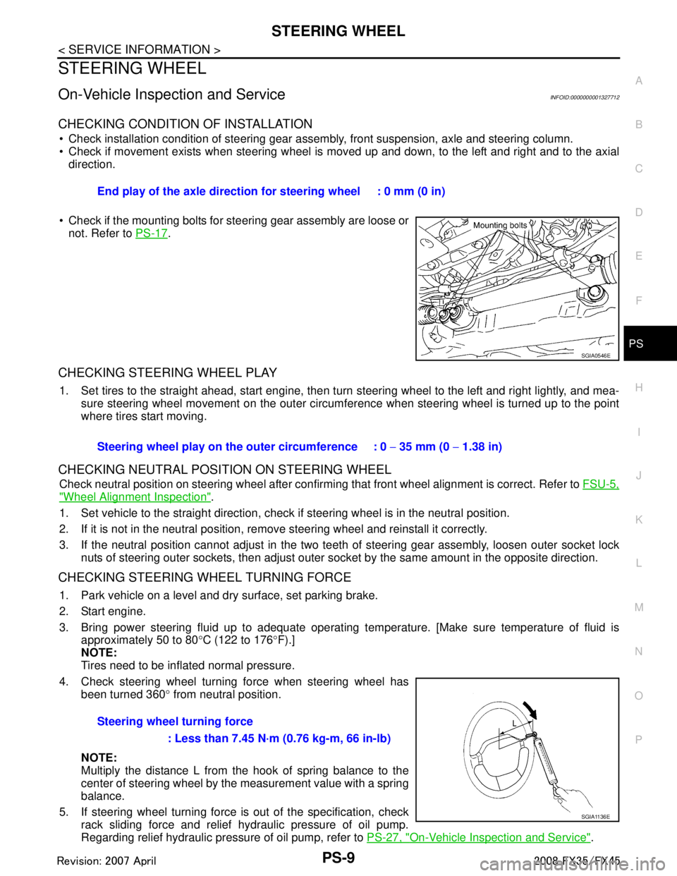
Check if the mounting bolts for steering gear assembly are loose or not. Refer to PS-17
.
CHECKING STEERING WHEEL PLAY
1. Set tires to the straight ahead, start engine, then turn steering wheel to the left and right lightly, and mea-
sure steering wheel movement on the outer circumfe rence when steering wheel is turned up to the point
where tires start moving.
CHECKING NEUTRAL POSITION ON STEERING WHEEL
Check neutral position on steering wheel after confirming that front wheel alignment is correct. Refer to FSU-5,
"Wheel Alignment Inspection".
1. Set vehicle to the straight direction, chec k if steering wheel is in the neutral position.
2. If it is not in the neutral position, remo ve steering wheel and reinstall it correctly.
3. If the neutral position cannot adjust in the two teeth of steering gear assembly, loosen outer socket lock
nuts of steering outer sockets, then adjust outer so cket by the same amount in the opposite direction.
CHECKING STEERING WHEEL TURNING FORCE
1. Park vehicle on a level and dry surface, set parking brake.
2. Start engine.
3. Bring power steering fluid up to adequate operating te mperature. [Make sure temperature of fluid is
approximately 50 to 80 °C (122 to 176 °F).]
NOTE:
Tires need to be inflated normal pressure.
4. Check steering wheel turning force when steering wheel has been turned 360 ° from neutral position.
NOTE:
Multiply the distance L from the hook of spring balance to the
center of steering wheel by the measurement value with a spring
balance.
5. If steering wheel turning force is out of the specification, check
rack sliding force and relief hydraulic pressure of oil pump.
Regarding relief hydraulic pressure of oil pump, refer to PS-27, "
On-Vehicle Inspection and Service".
End play of the axle direction for steering wheel : 0 mm (0 in)
SGIA0546E
Steering wheel play on the
outer circumference : 0 − 35 mm (0 − 1.38 in)
Steering wheel turning force : Less than 7.45 N·m (0.76 kg-m, 66 in-lb)
SGIA1136E
3AA93ABC3ACD3AC03ACA3AC03AC63AC53A913A773A893A873A873A8E3A773A983AC73AC93AC03AC3
3A893A873A873A8F3A773A9D3AAF3A8A3A8C3A863A9D3AAF3A8B3A8C
Page 3504 of 3924
RAX-6
< SERVICE INFORMATION >
REAR WHEEL HUB AND KNUCKLE
REAR WHEEL HUB AND KNUCKLE
On-Vehicle InspectionINFOID:0000000001327526
Make sure the mounting conditions (looseness, back lash) of each component and component status (wear,
damage) are normal.
WHEEL BEARING INSPECTION
With the vehicle raised, inspect the following.
Move wheel hub in the axial direction by hand. Che ck that there is no looseness of front wheel bearing.
Rotate wheel hub and make sure there is no unusual noi se or other irregular conditions. If there are any
irregular conditions, replace wheel hub and bearing assembly.
Removal and InstallationINFOID:0000000001327527
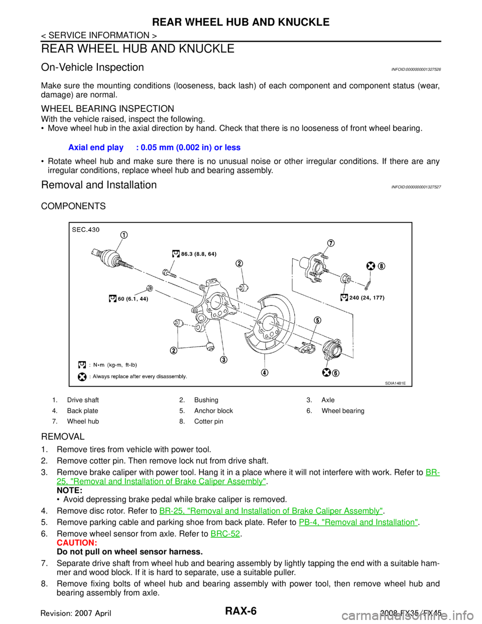
COMPONENTS
REMOVAL
1. Remove tires from vehicle with power tool.
2. Remove cotter pin. Then remove lock nut from drive shaft.
3. Remove brake caliper with power tool. Hang it in a place where it will not interfere with work. Refer to BR-
25, "Removal and Installation of Brake Caliper Assembly".
NOTE:
Avoid depressing brake pedal while brake caliper is removed.
4. Remove disc rotor. Refer to BR-25, "
Removal and Installation of Brake Caliper Assembly".
5. Remove parking cable and parking shoe from back plate. Refer to PB-4, "
Removal and Installation".
6. Remove wheel sensor from axle. Refer to BRC-52
.
CAUTION:
Do not pull on wheel sensor harness.
7. Separate drive shaft from wheel hub and bearing assembly by lightly tapping the end with a suitable ham- mer and wood block. If it is hard to separate, use a suitable puller.
8. Remove fixing bolts of wheel hub and bearing assembly with power tool, then remove wheel hub and bearing assembly from axle.Axial end play : 0.05 mm (0.002 in) or less
1. Drive shaft 2. Bushing 3. Axle
4. Back plate 5. Anchor block 6. Wheel bearing
7. Wheel hub 8. Cotter pin
SDIA1481E
3AA93ABC3ACD3AC03ACA3AC03AC63AC53A913A773A893A873A873A8E3A773A983AC73AC93AC03AC3
3A893A873A873A8F3A773A9D3AAF3A8A3A8C3A863A9D3AAF3A8B3A8C
Page 3818 of 3924
TF-32
< SERVICE INFORMATION >
TROUBLE DIAGNOSIS FOR SYMPTOMS
3. Start the engine, and then make sure that “4WD W/L” display turns from “ON” to “OFF” after several sec-
onds.
OK or NG
OK >> GO TO 6.
NG >> Perform trouble diagnosis for combination meter. Refer to DI-15, "
Trouble Diagnosis".
6.SYMPTOM CHECK
Check again.
OK or NG
OK >> INSPECTION END
NG >> Replace unified meter control unit assembly. Refer to DI-23, "
Disassembly and Assembly of Com-
bination Meter".
Heavy Tight-Corner Braking Symptom Occurs When the Vehicle Is Driven and the
Steering Wheel Is Turned Fu lly to Either Side after the Engine Is Started
INFOID:0000000001327452
NOTE:
Light tight-corner braking symptom may occur depending on driving conditions. This is not malfunc-
tion.
DIAGNOSTIC PROCEDURE
1.CHECK SYSTEM FOR CAN COMMUNICATION LINE
Perform self-diagnosis. Refer to TF-21, "
CONSULT-III Function (ALL MODE AWD/4WD)".
Is the
“CAN COMM CIRCUIT [U1000]” displayed?
YES >> Perform trouble diagnosis for CAN communication line. Refer to TF-28, "DTC U1000 CAN COMM
CIRCUIT".
NO >> GO TO 2.
2.CHECK ACCELERATOR PEDAL POSITION SIGNAL CIRCUIT
Perform self-diagnosis for ECM. Refer to EC-55, "
Emission-Related Diagnostic Information" (VQ35DE mod-
els) or EC-633, "
Emission-related Diagnostic Information" (VK45DE models).
Is any malfunction detec ted by self-diagnosis?
YES >> Check the malfunctioning system.
NO >> GO TO 3.
3.CHECK SYSTEM FOR AWD SOLENOID
Perform trouble diagnosis for AWD solenoid system. Refer to TF-25, "
DTC C1204 4WD SOLENOID".
OK or NG
OK >> GO TO 4.
NG >> Repair or replace damaged parts.
4.CHECK ELECTRIC CONTROLLED COUPLING
1. Turn ignition switch “OFF”.
2. Set the selector lever to “N” (neutral) position and disengage the parking brake.
3. Lift up the vehicle.
4. Rotate the rear propeller shaft by hand.
5. Hold front propeller shaft lightly.
Does front propeller shaft rotate?
YES >> Replace electric controlled coupling for mec hanical malfunction (clutch sticking etc.). Refer to TF-
40, "Disassembly and Assembly".
NO >> GO TO 5.
Monitor item Condition Display value
4WD W/L Ignition switch ON ON
Start engine (after several seconds) OFF
3AA93ABC3ACD3AC03ACA3AC03AC63AC53A913A773A893A873A873A8E3A773A983AC73AC93AC03AC3
3A893A873A873A8F3A773A9D3AAF3A8A3A8C3A863A9D3AAF3A8B3A8C